
Related Manuals for Sinclair SIH-09BIK2


Summary of Contents for Sinclair SIH-09BIK2
- Page 1 Service Manual Ver. 01 05 10 2022 KEYON SERIES SIH + SOH-09BIK2 SIH + SOH-12BIK2...
- Page 2 I M P O R T A N T N O T E : Read this manual carefully before installing or operating your new air conditioning unit. Make sure to save this manual for future reference.
-
Page 3: Table Of Contents
Table of Contents Service Manual Part I : Technical Information ........1 1. Summary ................. 1 2. Specifications ............... 2.1 Specification Sheet ....................2 2.2 Capacity Variation Ratio According to Temperature ........4 2.3 Cooling and Heating Data Sheet in Rated Frequency .........5 3. - Page 4 Service Manual 8.5 Installation of Indoor Unit ..................8.6 Installation of Outdoor unit ..................8.7 Vacuum Pumping and Leak Detection ...............38 8.8 Check after Installation and Test operation ............. 39 9. Maintenance ..............9.1 Error Code List ......................40 9.2 Procedure of Troubleshooting ................45 9.3 Troubleshooting for Normal Malfunction ............
-
Page 5: Part I : Technical Information
1. Summary Service Manual Indoor Unit: SIH-09BIK SIH-12BIK Outdoor Unit: SOH-09BIK2 SOH-12BIK2 Remote Controller: H O U R ONOF YAA1FB6(WiFi) Technical Information... -
Page 6: Specifications
2. Specifications Service Manual 2.1 Specification Sheet Model SIH + SOH-09BIK2 SIH + SOH-12BIK2 Rated Voltage 220-240 220-240 Power Rated Frequency Supply Phases Outdoor Outdoor Power Supply Mode Cooling Capacity 2700 3200 Heating Capacity 2800 3400 Cooling Power Input Heating Power Input Cooling Current Input 3.45 4.14... - Page 7 Service Manual Outdoor Unit Model SOH-09BIK2 SOH-12BIK2 ZHUHAI LANDA ZHUHAI LANDA Compressor Manufacturer COMPRESSOR CO.,LTD COMPRESSOR CO., LTD Compressor Model QXF-A082zC170 QXF-N088zC170 Compressor Oil ZE-G;ES RB68GX or equivalent FW68DA or equivalent Compressor Type Rotary Rotary Compressor LRA. Compressor RLA 2.56 Compressor Power Input Compressor Overload Protector Throttling Method...
-
Page 8: Capacity Variation Ratio According To Temperature
Service Manual 2.2 Capacity Variation Ratio According to Temperature Heating operation ambient temperature range is -15ºC~24ºC Heating Cooling + SOH -09BIK + SO H-09BI Condi tions onditi door: DB27° B19° Indoo :DB2 0° door air flo Indoo air fl ow:Su per Hi pe le ngth:... -
Page 9: Cooling And Heating Data Sheet In Rated Frequency
Service Manual 2.3 Cooling and Heating Data Sheet in Rated Frequency Cooling: Pressure of gas pipe Rated cooling Inlet and outlet pipe temperature of heat connecting indoor and Fan speed of Fan speed of condition(°C) (DB/WB) exchanger Model outdoor unit indoor unit outdoor unit Indoor... -
Page 10: Outline Dimension Diagram
3. Outline Dimension Diagram Service Manual 3.1 Indoor Unit SIH-09BIK SIH-12BIK Φ55 Φ55 Unit:mm Models 129.5 178.5 SIH-09BIK SIH-12BIK Technical Information... -
Page 11: Outdoor Unit
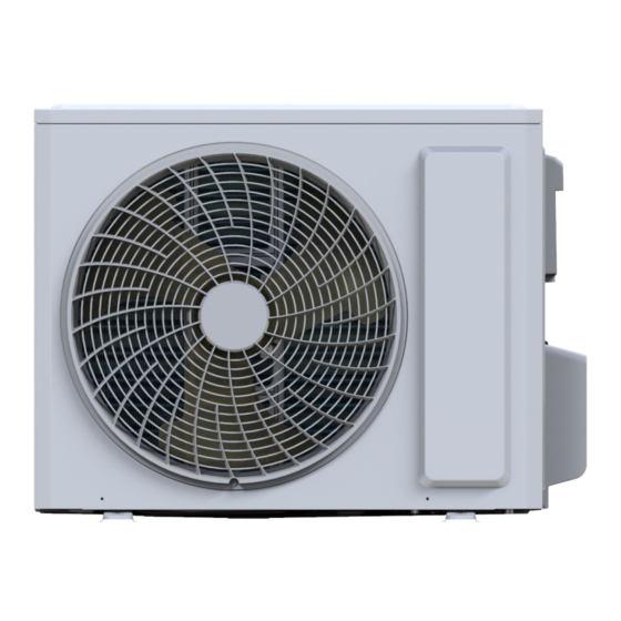
Service Manual 3.2 Outdoor Unit SOH-09BIK2 SOH-12BIK2 Unit:mm Technical Information... -
Page 12: Refrigerant System Diagram
(evaporator) Suction Accumlator 4. Refrigerant System Diagram Compressor Heat Service Manual exchanger Liquid pipe (condenser) side Cooling and heating model Valve Capillary Strainer COOLING SIH + SOH-09BIK2 SIH + SOH-12BIK2 In door unit Outdoor unit Gas pipe side Valve 4-Way valve Di s charge Heat Suction... -
Page 13: Electrical Part
5. Electrical Part Service Manual 5.1 Wiring Diagram ●Instruction Symbol Symbol Color Symbol Symbol Color Symbol Name White Green Jumper cap Yellow Brown COMP Compressor Blue Grounding wire YEGN Yellow/Green Black Violet Orange Note: Jumper cap is used to determine fan speed and the swing angle of horizontal lover for this model. ●... - Page 14 Service Manual SIH-12BIK 60000700068804 Technical Information...
- Page 15 Service Manual ● Outdoor Unit SOH-09BIK2 SOH-12BIK2 WARNING OPTIONAL OPTIONAL OPTIONAL Bottom 4-WAY OUTTUBE OUTROOM EXHAUST ELECTRONIC Please don't touch any Band EXPANSION VALVE TEMP. TEMP. TEMP. VALVE terminal when the machine is Heater SENSOR SENSOR SENSOR running ,stopping or has been powered off for less than 30 minutes to prevent the risk RT 3...
-
Page 16: Pcb Printed Diagram
Service Manual 5.2 PCB Printed Diagram Indoor Unit SIH-09BIK Name Name Fuse Auto button Live wire interface Interface of PG feedback interface Interface of health function neutral wire(only for the model with this 10 Swing interface function) Neutral wire interface Jumper cap Fan motor interface of PG 12 Interface of temperature sensor... - Page 17 Service Manual SIH-12BIK Name Name Interface of health function 10 WIFI terminal neutral wire Neutral wire terminal Wired controller terminal Motor terminal 12 Interface of display board Interface of health function 13 Jumper cap live wire Communication terminal for Auto button indoor unit and outdoor unit Terminal of live wire used for Up&down swing terminal...
- Page 18 Service Manual Outdoor Unit SOH-09BIK2 SOH-12BIK2 Name Earthing wire Neutral wire, live wire and communication cable 4-way valve Electric heating belt of chasssis Outdoor fan Electronic expansion valve Overload Temperature sensor Three-phase terminal of compressor Technical Information...
-
Page 19: Function And Control
6. Function and Control Service Manual 6.1 Remote Controller Introduction Buttons on remote controller Introduction for buttons on remote controller NOTE: ● This is a general use remote controller, it could be used for the air conditioners with multifunction; For some function, which the model doesn't have, if press the corresponding button on the remote controller that the unit will keep the original running status. - Page 20 Service Manual OFF is defaulted. X-FAN is not available in AUTO, FAN or HEAT ● When selecting " " or no display with remote controller, mode. temperature indicator on indoor unit displays set temperature. This function indicates that moisture on evaporator of indoor unit ●...
- Page 21 Service Manual Function introduction for combination buttons Replacement of batteries in remote controller Combination of "+" and "-" buttons: About Child lock Press " + " and " - " buttons simultaneously to lock or unlock the keypad. If the remote controller is locked, is displayed.
-
Page 22: Brief Description Of Models And Functions
Service Manual 6.2 Brief Description of Models and Functions Indoor Unit speed and swing function is turned on. Press this auto button at ● ON status to turn off the unit. (3) Auto fan 1.Basic function of system Heating mode: During auto heating mode or normal heating ode, (1)Cooling mode auto fan speed will adjust the fan speed automatically according (1) Under this mode, fan and swing operates at setting status. - Page 23 Service Manual will be displayed. Outdoor Unit ● 2. Only when remote control signal is switched to indoor ambient temperature display status (corresponding remote control code: 10) from other display status (corresponding remote control code: 1. Cooling mode: 00, 01,11),controller will display indoor ambient temperature for 3s Working condition and process of cooling mode: and then turn back to display set temperature.
- Page 24 Service Manual ⑥ Under the condition that compressor is turned on, when unit is changed to heating mode from cooling or drying mode, 4-way 1. Input Parameter Compensation and Calibration valve will be energized in 2~3mins delay. Note: Tcompensation is determined by IDU and ODU. If IDU (1) Check the ambient temperature compensation controls the compensation temperature, then Tcompensation is function Indoor ambient temperature compensation...
- Page 25 Service Manual temperature can be set at: 25~30ºC (Cooling at low temperature), (Note: The indoor units have a function of power memory, the that is, the minimum setting temperature for outer units judgment machine can be restarted after remote shutdown and powering up is 25ºC .
- Page 26 Service Manual Evaporator frozen-preventing protection function is allowed to If [T ] ≤T < [T Cooling overload frequency reducing temperature at high speed outer pipe Cooling begin after 6 min of starting the compressor. ] , you should adjust the compressor overload power turn-off temperature 1.
- Page 27 Service Manual running 90s at the lower limit, if T heating overload frequency continuously occurs for six times, it should not be resumed reducing temperature at normal speed ≤T outer pipe, then Cooling automatically, and you should press the ON/OFF button to overload protects machine stopping;...
- Page 28 Service Manual protection: The machine should be stopped or transferred to shall stop working for overcurrent protection; if [I ]≤[I Phase Current supply air, the trouble should be cleared immediately, and the ], and the compressor have stopped working Frequency Reducing Phase Current protection times are not counted.
- Page 29 Service Manual reversion abnormity protection for four-way valve 3 min; and if it operate; still can’t run when the reversion abnormity protection for four- (2) When Toutdoor amb.>2 , the electric heating of chassis will way valve happens to stop working for 3 times in succession, it is stop operation;...
-
Page 30: Ewpe Smart App Operation Manual
Service Manual 6.3 Ewpe Smart App Operation Manual Control Flow Chart Internet Cloud intelligent Home Wi-Fi Cellular/ home Other Wi-FI appliances Home wireless router Home Wi-Fi Operating Systems Requirement for User's smart phone: iOS system Android system Support iOS7.0 and Support Android 4.4 and above version above version... -
Page 31: Part Ii : Installation And Maintenance
7. Notes for Installation and Maintenance Service Manual Safety Precautions: Important! 11. For the air conditioner without plug, an air switch must be installed in the circuit. The air switch should be all-pole parting and the contact parting distance should be more than Please read the safety precautions carefully before 3mm. - Page 32 Service Manual Safety Precautions for Installing and Relocating the Unit: To ensure safety, please be mindful of the following precautions. WARNINGS 1. When installing or relocating the unit, be sure to 5.When installing the unit, make sure that connection keep the refrigerant circuit free from air or substances pipe is securely connected before the compressor other than the specified refrigerant.
- Page 33 Service Manual Safety Precautions for Refrigerant ●The air conditioner is not allowed to use in a room that has running fire (such as fire source,working coal gas ware, ●To realize the function of the air conditioner unit, a special operating heater). refrigerant circulates in the system.
- Page 34 Service Manual ●Make sure that there isnt any naked flame near the outlet of the vacuum pump and its well-ventilated. ●The refrigerant should be recycled into the specialized storage tank. Filling the refrigerant ●Use the refrigerant filling appliances specialized for R32. Make sure that different kinds of refrigerant wont contaminate with each other.
- Page 35 Service Manual Main Tools for Installation and Maintenance Level meter Measuring tape Screw driver Impact drill Drill head Electric drill Electroprobe Universal meter Inner hexagon Electronic Torque wrench Open-end wrench spanner leakage detector Vacuum pump Pressure meter Pipe pliers Pipe pliers Pipe cutter Pipe expander Pipe bender...
-
Page 36: Installation
8. Installation Service Manual 8.1 Installation Dimension Diagram Space to the wall At least 15cm Space to the wall At least 15cm Space to the obstruction At least 50cm Drainage pipe Installation and Maintenance... - Page 37 Service Manual Installation Procedures Start installation Preparation before installation Read the requirements select installation Prepare tools for electric connection location Select indoor unit Select outdoor unit installation location installation location Install the support of outdoor unit Install wall-mounting (select it according to the actual situation) frame, drill wall holes Connect pipes of indoor Fix outdoor unit...
-
Page 38: Installation Parts-Checking
Service Manual 8.2 Installation Parts-checking 3. Outdoor Unit: (1) Select a location where the noise and outflow air emitted by the outdoor unit will not affect neighborhood. Name (2) The location should be well ventilated and dry, in which the Indoor unit outdoor unit wont be exposed directly to sunlight or strong wind. -
Page 39: Installation Of Indoor Unit
Service Manual 8.5 Installation of Indoor Unit 4. Outlet Pipe (1) The pipe can be led out in the direction of right, rear right, left 1. Choosing Installation Iocation or rear left.(As show in Fig.3) Recommend the installation location to the client and then confirm (2) When selecting leading out the pipe from left or right, please it with the client. - Page 40 Service Manual 6. Install Drain Hose (1) Connect the drain hose to the outlet pipe of indoor unit.(As SIH-09BIK show in Fig.8) SIH-12BIK (2) Bind the joint with tape.(As show in Fig.9) blue black brown yellow- green Fig.13 Drain hose Outdoor unit connection Outlet pipe Note: The wiring connect is for reference only, please refer to...
-
Page 41: Installation Of Outdoor Unit
Service Manual Note: (1) The power cord and control wire cant be crossed or winding. (2) The drain hose should be bound at the bottom. 9. Hang the Indoor Unit Drain vent (1) Put the bound pipes in the wall pipe and then make them pass Chassis Drain hose Outdoor drain joint... -
Page 42: Vacuum Pumping And Leak Detection
Service Manual 5. Connect Outdoor Electric Wire (1) Remove the wire clip; connect the power connection wire and signal control wire (only for cooling and heating unit) to the wiring terminal according to the color; fix them with screws.(As show in The drain hose can't be fluctuant Fig.23) The water outlet... -
Page 43: Check After Installation And Test Operation
Service Manual 8.8 Check after Installation and Test operation 1. Check after Installation Check according to the following requirement after finishing installation. Items to be checked Possible malfunction Has the unit been installed The unit may drop, shake or firmly? emit noise. -
Page 44: Maintenance
9. Maintenance Service Manual 9.1 Error Code List Display Method Possible Causes(For specific maintenance Malfunction of Indoor Unit A/C Status method, please refer to the following procedure of Name (Error Code) troubleshooting) During cooling and drying operation, Possible reasons: High pressure except indoor fan operates, all loads 1. - Page 45 Service Manual During cooling and drying operating, Outdoor ambient Outdoor temperature sensor hasnt been connected well or is compressor stops while indoor fan temperature sensor is damaged. Please check it by referring to the resistance table operates; During heating operation, the open/short circuited for temperature sensor) complete unit will stop operation...
- Page 46 Service Manual During cooling and drying operation, Malfunction of module compressor will stop while indoor fan will temperature sensor operate; Replace outdoor control panel AP1 During heating operation, the complete circuit unit will stop After the complete unit is de-energized for 20mins, check During cooling operation, compressor will Module high whether the thermal grease on IPM Module of outdoor...
- Page 47 Service Manual During cooling and drying operation, Malfunction of phase compressor will stop while indoor fan will current detection Replace outdoor control panel AP1 operate; During heating operation, the circuit for compressor complete unit will stop During cooling and drying operation, Malfunction of voltage compressor will stop while indoor fan will dropping for DC...
- Page 48 Service Manual If malfunction occurs,corresponding code will display and the unit will resume normal until protection or malfunction disappears. Installation and Maintenance...
-
Page 49: Procedure Of Troubleshooting
Service Manual 9.2 Procedure of Troubleshooting ●Indoor unit: 1. Malfunction of Temperature Sensor F1, F2 Main detection points: ● Is the wiring terminal between the temperature sensor and the controller loosened or poorly contacted? ● Is there short circuit due to trip-over of the parts? ●... - Page 50 Service Manual 2. Malfunction of Blocked Protection of IDU Fan Motor H6 Main detection points: ● SmoothlyIs the control terminal of PG motor connected tightly? ● SmoothlyIs the feedback interface of PG motor connected tightly? ● The fan motor can't operate? ●...
- Page 51 Service Manual 3. Malfunction of Protection of Jumper Cap C5 Main detection points: ● Is there jumper cap on the mainboard? ● Is the jumper cap inserted correctly and tightly? ● The jumper is broken? ● The motor is broken? ●...
- Page 52 Service Manual 4. Malfunction of Zero-crossing Inspection Circuit Malfunction of the IDU Fan Motor U8 Main detection points: ● Instant energization afte de-energization while the capacitordischarges slowly? ● The zero-cross detectioncircuit of the mainboard is defined abnormal? Malfunction diagnosis process: Start Turn power off for 1minute,the turn...
- Page 53 Service Manual 5. High Temperature and Overload Protection (AP1 below means control board of outdoor unit) E8 Start Normal protection, please use it Unit restarts If the outdoor ambient temperature is after improving the outdoor ambient normally higher than 53°C? temperature Improve the radiating environment of Unit restarts...
- Page 54 Service Manual 6. Malfunction of detecting plate(WIFI) JF Start check if the connection wire are correctly connected detecting Replace the plate with the same model Is malfunction eliminated Replace the mainboard with the same model The end Installation and Maintenance...
- Page 55 Service Manual ●Outdoor unit: 1.Capacity charging malfunction (outdoor unit malfunction) (AP1 below is control board of outdoor unit) Main detection point: ● Detect if the voltage of L and N terminal of wiring board is between 210AC-240AC by alternating voltage meter; ●...
- Page 56 Service Manual 2.Diagnosis for anti-high temperature, overload protection (AP1 below is control board of outdoor unit) Main detection point: ● If the outdoor ambient temperature is in normal range; ● If the indoor and outdoor fan is running normal; ● If the radiating environment of indoor and outdoor unit is well. Malfunction diagnosis process: Anti-high temperature, overload protection...
- Page 57 Service Manual 3.IPM protection, phase current overcurrent (the control board as below indicates the control board of outdoor unit) H5/P5 Mainly detect: (1) Compressor COMP terminal (2) voltage of power supply (3) compressor (4) Refrigerant-charging volume (5) air outlet and air inlet of outdoor/indoor unit Troubleshooting: Turn on the unit after energization...
- Page 58 Service Manual 4. Start-up failure (following AP1 for outdoor unit control board) Mainly detect: ●Whether the compressor wiring is connected correct? ●Is compressor broken? ●Is time for compressor stopping enough? Fault diagnosis process: Power on the unit Restart it up after Is stop time of the compressor 3 minutes longer than 3 minutes?
- Page 59 Service Manual 5. Out of step diagnosis for the compressor (AP1 hereinafter refers to the control board of the outdoor unit) Mainly detect: ●Is the system pressure too high? ●Is the input voltage too low? Fault diagnosis process: Out of step occurs once the Out of step occurs in unit is powered on.
- Page 60 Service Manual 6. Overload and air exhaust malfunction diagnosis (following AP1 for outdoor unit control board) Mainly detect: ●Is the PMV connected well or not? Is PMV damaged? ●Is refrigerant leaked? Fault diagnosis process: 20 minutes after the complete unit is powered off Is the terminal FA for the Connect the...
- Page 61 Service Manual 7. Communication malfunction: (following AP1 for outdoor unit control board) Mainly detect: ●Is there any damage for the indoor unit mainboard communication circuit? Is communication circuit damaged? ●Detect the indoor and outdoor units connection wire and indoor and outdoor units inside wiring is connect well or not, if is there any damage? Fault diagnosis process:...
- Page 62 Service Manual 8. Malfunction of Overcurrent Protection Main detection points: ● Is the supply voltage unstable with big fluctuation? ● Is the supply voltage too low with overload? ● Hardware trouble? Malfunction diagnosis process: Start Is malfunction Is the supply voltage unstable of the rated voltage on the nameplate eliminated Is the supply voltage too low...
-
Page 63: Troubleshooting For Normal Malfunction
Service Manual 9.3 Troubleshooting for Normal Malfunction 1. Air Conditioner Can'tbe Started Up Possible Causes Discriminating Method (Air conditioner Status) Troubleshooting Confirm whether its due to power failure. If yes, No power supply, or poor connection After energization, operation indicator isnt bright wait for power recovery. - Page 64 Service Manual 4. ODU Fan Motor Can'tOperate Possible causes Discriminating method (air conditioner status) Troubleshooting Wrong wire connection, or poor Check the wiring status according to circuit Connect wires according to wiring diagram to make connection diagram sure all wiring terminals are connected firmly Measure the capacity of fan capacitor with an Capacity of the ODU fan motor is universal meter and find that the capacity is out of...
-
Page 65: Removal Procedure
10. Removal Procedure Service Manual 10.1 Removal Procedure of Indoor Unit Caution: discharge the refrigerant completely before removal. SIH-09BIK SIH-12BIK Step Procedure 1.Remove filter Panel Open the panel. Clasps Loosen the clasp shown in the fig and then pull the left filter and right filer outwards to remove them. - Page 66 Service Manual Step Procedure Panel 3.Remove panel Open the front panel; separate the panel rotation shaft Front panel from the groove fixing the front panel and then removes the front panel. Note: The display of some models is fixed on the panel; Panel rotation unscrew the screws fixing the display on the panel before removing the panel.
- Page 67 Service Manual Step Procedure 6.Remove electric box assy Electric box Loosen the connection clasps between Cold plasma generator and electric box, and then remove the cold plasma generator. Clasps Step motor Grounding Indoor tube temperature sensor screw Electric box assy ①...
- Page 68 Service Manual Step Procedure 7.Remove evaporator assy Remove 3 screws fixing evaporator assy. Screw At the back of the unit, Loosen the clasp,connection pipe clamp and then remove the connection pipe Connection pipe clamp clamp. Clasp Groove Rear Case assy First remove the left side of evaporator from the groove of bottom shell and then remove the right side from the clasp on the bottom shell.
- Page 69 Service Manual Step Procedure 8.Remove motor and cross flow blade Motor clasp Remove 3 screws fixing motor clamp and then remove the motor clamp. Screws Cross flow Remove the at the connection place of cross flow blade Motor and motor; lift the motor and cross flow blade upwards to remove them.
-
Page 70: Removal Procedure Of Outdoor Unit
Service Manual 10.2 Removal Procedure of Outdoor Unit Caution: discharge the refrigerant completely before removal. SOH-09BIK2 SOH-12BIK2 Step Procedure 1. Before disassembly 2. Remove big handle and valve cover big handle Remove the connection screw fixing the big handle and then remove the valve cover. - Page 71 Service Manual Step Procedure 4. Remove grille grille Remove connection screws between the front grille and the front panel. Then remove the grille. 5. Remove front panel Remove connection screws connecting the front panel with the chassis and the motor support and then remove the front panel.
- Page 72 Service Manual Step Procedure 7. Remove axial flow blade axial flow blade Remove the nut on the blade and then remove the axial flow blade. 8. Remove motor and motor support motor support Remove the tapping screws fixing the motor and motor disconnect the leading wire insert of the motor.
- Page 73 Service Manual Step Procedure 10. Remove isolation sheet Remove the screws fixing the isolation sheet and then remove the isolation sheet. isolation sheet 11. Remove compressor 4-way valve Unsolder the welding joint connecting the capillary, valves and the outlet pipe of condenser to remove the capillary.
-
Page 74: Appendix
Appendix Service Manual Appendix 1: Reference Sheet of Celsius and Fahrenheit Conversion formula for Fahrenheit degree and Celsius degree: Tf=Tcx1.8+32 Set temperature Fahrenheit display Fahrenheit Celsius Fahrenheit display Fahrenheit Celsius Fahrenheit display Fahrenheit Celsius temperature(℉) temperature(℉) temperature(℉) (℉) (℃) (℉) (℃)... -
Page 75: Appendix 3: Pipe Expanding Method
Service Manual Appendix 3: Pipe Expanding Method Pipe Note: Improper pipe expanding is the main cause of refrigerant leakage.Please expand Pipe cutter the pipe according to the following steps: A:Cut the pip Leaning Uneven Burr ● Confirm the pipe length according to the distance of indoor unit and outdoor unit. ●... -
Page 76: Appendix 4: List Of Resistance For Temperature Sensor
Service Manual Appendix 4: List of Resistance for Temperature Sensor Resistance Table of Ambient Temperature Sensor for Indoor and Outdoor Units(15K) Temp( Resistance(kΩ) Temp( Resistance(kΩ) Temp( Resistance(kΩ) Temp( Resistance(kΩ) 138.10 49.02 18.75 7.97 128.60 44.31 17.14 7.35 115.00 40.09 15.68 6.79 102.90 36.32... - Page 77 United Kingdom www.sinclair-world.com This product was manufactured in China (Made in China). R E P R E S E N T A T I V E SINCLAIR Global Group s.r.o. Purkynova 45 612 00 Brno Czech Republic T E C H N I C A L S U P P O R T SINCLAIR Global Group s.r.o.
- Page 78 N O T E S...
- Page 79 N O T E S...
Need help?
Do you have a question about the SIH-09BIK2 and is the answer not in the manual?
Questions and answers