Advertisement
MISE - STEREO ENCODER
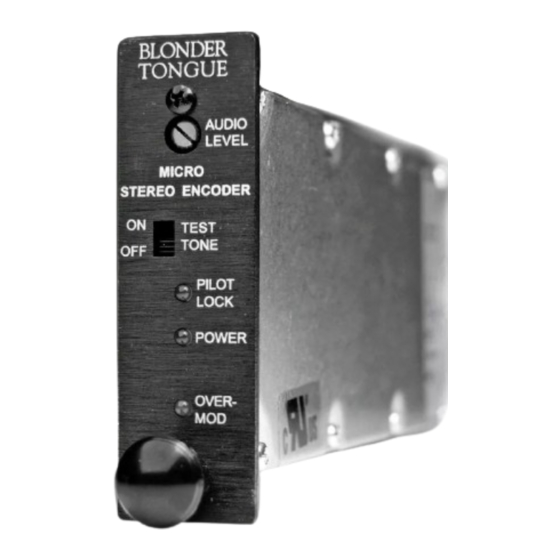
1. FRONT PANEL CONTROLS and INDICATORS
F1:AUDIO LEVEL Control
The setting of this screwdriver adjustment determines the audio input signal level. After system
audio modulation levels are properly set, and with left and right audio signals within the 250
mVrms to 2.5 V rms range, set this control to a point where the OVERMODULATION
indicator just remains off (see item F5).
F2:TEST TONE Switch
Switch to the 'ON' position to enable an internal test tone to aid system audio level setup. See
the 'Installation' section of this manual for setup information. The normal position of this
switch is the 'OFF' position.
F3:PILOT LOCK Indicator
Lights to indicate that a video signal is applied to the rear panel VIDEO INPUT connector and
that the STEREO ENCODER is locked to the video horizontal sync.
F4:POWER Indicator
Lights when the unit is connected to the required source of DC power.
F5:OVERMODULATION Indicator
Lights to indicate greater than 25 KHz of main channel deviation. After system audio
modulation levels are properly set, and with left and right audio source input, adjust the AUDIO
LEVEL control (see item F1) to a point where the OVERMODULATION indicator just remains
off.
AUDIO
F1
LEVEL
F2
PILOT
F3
LOCK
F4
POWER
OVER-
F5
MOD
Advertisement
Table of Contents

Related Manuals for Blonder tongue MISE


Summary of Contents for Blonder tongue MISE
- Page 1 MISE - STEREO ENCODER 1. FRONT PANEL CONTROLS and INDICATORS AUDIO LEVEL PILOT LOCK POWER OVER- F1:AUDIO LEVEL Control The setting of this screwdriver adjustment determines the audio input signal level. After system audio modulation levels are properly set, and with left and right audio signals within the 250 mVrms to 2.5 V rms range, set this control to a point where the OVERMODULATION...
- Page 2 2. REAR PANEL CONNECTIONS / INTERNAL JUMPERS R1:VIDEO INPUT Connector This is the baseband video input to the STEREO ENCODER which provides the encoder circuitry with the modulator horizontal sync information. The baseband video to the modulator must be ‘looped through’ this input using an external ‘F’ type Tee (T) connector.
- Page 3 4. INS 3. INSTALLATION – AUDIO LEVEL SETTINGS METHOD 1: Connect the STEREO ENCODER, Audio/Video Modulator, compatible DC power source, video source signal and test equipment as shown. Make certain that the audio response of the A/V modulator is set for ‘FLAT’ (pre-emphasis defeated).
- Page 4 4. INSTALLATION – AUDIO LEVEL SETTING, continued Set the STEREO ENCODER TEST TONE switch to the ‘OFF’ position. Connect Left and Right audio source signals to the STEREO ENCODER. Set the ‘Audio LEVEL’ control on the STEREO ENCODER to a point where the ‘OVERMODULATION’...
- Page 5 5. SPECIFICATIONS AUDIO INPUT Input Impedance: 20K Ohms unbalanced. Input Level: 250 mVrms ~ 2.5 Vrms, Adjustable VIDEO INPUT Input Impedance: 10 Kohm min. Input Level Range: 0.5 Vp-p to 2 Vp-p COMPOSITE OUTPUT Output Impedance: 100 Ohms Output Level: 1.1 Vp-p @100% modulation STEREO PERFORMANCE Stereo Separation:...
Need help?
Do you have a question about the MISE and is the answer not in the manual?
Questions and answers