Table of Contents
Advertisement
Quick Links
MPEG-2 SD Encoder/Multiplexer
SDE-6S-ASI
6xSD-SDI/6xNTSC – 2xASI/1xIP - 16 Audio Inputs and SCTE-35 Control
©2014 Blonder Tongue Laboratories, Inc. All rights reserved. Specifications are subject to change without notice. Trademarks are the property of their respective owner.
Status
Date
FINAL
July 17, 2014
800-523-6049
www.blondertongue.com
Document No.
Issue No.
651233400A
1
Stock No.
Stock No.
6365
6365
USER MANUAL
USER MANUAL
Author
KK
Advertisement
Table of Contents

Related Manuals for Blonder tongue SDE-6S-ASI


Summary of Contents for Blonder tongue SDE-6S-ASI
- Page 1 6xSD-SDI/6xNTSC – 2xASI/1xIP - 16 Audio Inputs and SCTE-35 Control Status Date Document No. Issue No. Author FINAL July 17, 2014 651233400A 800-523-6049 www.blondertongue.com ©2014 Blonder Tongue Laboratories, Inc. All rights reserved. Specifications are subject to change without notice. Trademarks are the property of their respective owner.
- Page 2 We recommend that you write the following information in the spaces provided below. Purchase Location Name: Purchase Location Telephone Number: SDE-6S-ASI Serial Number: The information contained herein is subject to change without notice. Revisions may be issued to advise of such changes and/or additions.
-
Page 3: Table Of Contents
SDE-6S-ASI User Manual Table of Contents SECTION 1 – GENERAL & SAFETY INSTRUCTIONS ....................... 4 SECTION 2 – PRODUCT SUMMARY ..........................6 2.1 REVISION HISTORY & REASON ..........................6 2.2 PRODUCT APPLICATION & DESCRIPTION ....................... 6 2.3 PRODUCT SPECIFICATION ............................12 SECTION 3 –... -
Page 4: Section 1 - General & Safety Instructions
Unplug the unit from the AC power outlet before cleaning. Use only a damp cloth for cleaning the exterior of the unit. ➥ ➥ Do not use accessories or attachments not recommended by Blonder Tongue, as they may cause hazards, and will void the warranty. Do not operate the unit in high-humidity areas, or expose it to water or moisture. ➥... - Page 5 ➥ The unit exhibits a distinct change in performance. ➥ When replacement parts are required, ensure that the service technician uses replacement parts specified by Blonder Tongue. Unauthorized substitutions may damage the unit or cause electrical shock or fire, and will void the warranty.
-
Page 6: Section 2 - Product Summary
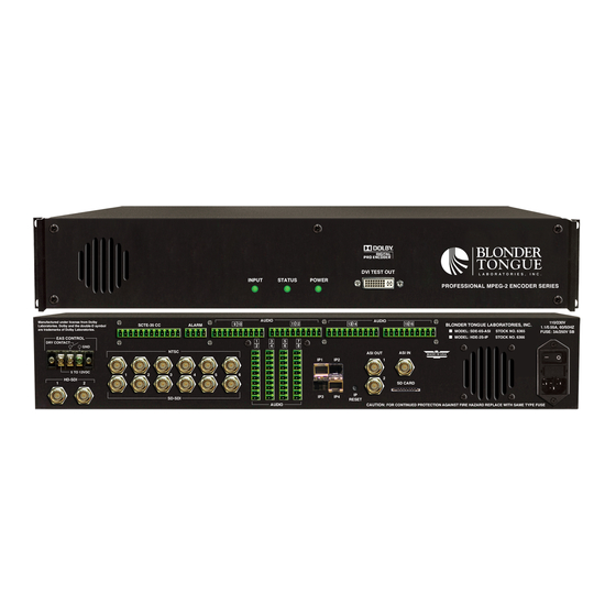
2.2 Product Application & Description Application: SDE-6S-ASI (MPEG-2 SD Encoder/Multiplexer – 6xSD-SDI/6xNTSC – 2xASI/1xIP) accepts up to six (6) standard-definition (SD) programs from any of the following inputs: 6xSD-SDI, and 6xNTSC. MPEG-2 encoded outputs are multiplexed into one Multi- Program Transport Stream (MPTS) which is available in the following formats simultaneously: 2x, and 1xIP (100/1000 Base-T). - Page 7 SDE-6S-ASI User Manual Description: Front panel connectors and indicators: POWER LED: This will be Green if unit is powered. Off when there is no power. POWER DESCRIPTION Green Unit is powered on and the power supply is functioning properly. Unit power is disconnected/switched off, or the power input fuse is blown/the power supply has failed...
- Page 8 8 SDE-6S-ASI User Manual STATUS INPUT DESCRIPTION Blinking Green Blinking Green System Reset Button pressed for less than 5 seconds. Upon button release, encoder continues normal operation. Blinking Yellow Blinking Yellow System Reset Button pressed for 5 seconds. Upon button release, encoder reboots.
- Page 9 SDE-6S-ASI User Manual Front panel connectors and indicators: NOTE: Pin 1 -48VDC Opt. Stock #6365 48 14,15,16 NOTE: Audio inputs 1-6 NOTE: Pin 1 (only) may be used for SCTE-36 cue tone detection. EAS CONTROL: Terminal strip to activate the EAS messaging feature in one of two the following ways: Dry contact &...
- Page 10 10 SDE-6S-ASI User Manual NOTE: Audio inputs 1-6 may be used for SCTE-35 Cue Tone detection. AUDIO TERMINAL BLOCK INPUTS CONTACT AUDIO AUDIO AUDIO AUDIO Audio #1 Audio #3 Audio #5 Audio #7 Audio #1 Audio #3 Audio #5 Audio #7...
- Page 11 SDE-6S-ASI User Manual GIGE ETHERNET PORTS: a) IP1 - SFP Plug-in 10/100baseT Ethernet Control - Comprehensive remote monitoring and control via any standard web browser through the 10/100 BaseT Ethernet Interface. SFP module is included. b) IP2 - not used c) IP3 - not used d) IP4 - Ethernet Output - SFP Connector 10/100/1000Base-T.
-
Page 12: Product Specification
12 SDE-6S-ASI User Manual 2.3 Product Specification Specifications Input Output SD-SDI Connectors: 6x BNC Connector: 2x BNC (Rear-panel) Standard: SMPTE 259M Format: DVB-ASI Video Resolution: 480i Standard: ETSI EN 50083-9 Embedded PCM and pass-through Dolby ® Digital Audio: Analog Stereo Balanced Audio... -
Page 13: Section 3 - Installation & Power-Up
Six-foot DVI to HDMI cable (QTY=1) 3.2 Installation The SDE-6S-ASI encoder is designed to be installed in a standard 19-inch (483 mm) rack (EIA 310-D, IEC 60297, and DIN 41494 SC48D). To install the encoder, secure the unit’s front panel to the rack by inserting four (4) machine screws, with cup washers, through the four (4) mounting holes in the front panel. -
Page 14: Section 4 - Communicating With The Unit
14 SDE-6S-ASI User Manual Section 4 – Communicating with the Unit Local or remote communication with the unit is only possible through a GUI-based menu via any standard web browser. Before you can communicate with the unit, you must configure the unit's IP address to conform to your existing IP network or LAN. -
Page 15: Section 5 - Configuring The Unit
SDE-6S-ASI User Manual Section 5 – Configuring the Unit 5.1 Accessing the Unit via a Web Browser You must complete the steps described in Section 4 before proceeding as follows: (1) Open a web browser on your computer (Internet Explorer 7 or higher is recommended) and enter the following URL address (http://172.16.70.1). -
Page 16: Main > Status" Screen
16 SDE-6S-ASI User Manual 5.2 "Main > Status" Screen The “Main > Status” screen (Figure 5.2) is a “read only” screen and displays Input, PID and Output information of each of the six (6) programs in the transport stream. Figure 5.2 - "Main > Status" Screen... - Page 17 SDE-6S-ASI User Manual In the section entitled “TS (Transport Stream)” under yellow header, the following parameters about each input program in the TS are displayed: TS Mapping: TS1 : indicates the top level transport stream name. The bold heading under Bitrates shows the actual overall bitrate over the prescribed bitrate (set in TS Config section, Section 5.XX)
-
Page 18: Main > Video" Screen
18 SDE-6S-ASI User Manual 5.3 "Main > Video" Screen The “Main > Video” screen (Figure 5.3) is a “user-configurable” screen where the following input source parameters can be configured. Some parameters are read only and are not configurable. Figure 5.3 - "Main > Video" Screen... - Page 19 SDE-6S-ASI User Manual ENCODED VIDEO: Maximum Format Size: (480i) Indicates the resolution of the incoming video Video Source: (6xNTSC, 6xSD/SDI, 2xHD/SDI) Indicates the video inputs source Video Input Signal Status: this field will indicate whether the video is valid on the input.
-
Page 20: Main > Audio" Screen
20 SDE-6S-ASI User Manual 5.4 "Main > Audio" Screen The “Main > Audio” screen (Figure 5.4) is a “user-configurable” screen and includes the following sub-tabs: Encoded Audio and Programs. Figure 5.4 “Main/Audio” Screen... - Page 21 Right Channel Track: This setting only applies to audio embedded in the incoming SD/SDI and HD/SDI streams. Any one of the embedded audios can be used here. Audio Digitizer Sample Rate: indicates the input sampling rate of the encoder. The SDE-6S-ASI supports 48 kHz sampling rate.
-
Page 22: Main > Scte 35" Screen
22 SDE-6S-ASI User Manual Default Audio Language: Defines the language of the audio to be sent in the outgoing stream. Encoded Audio Bitrate: Defines the outgoing audio bit rate. Encoded Audio Scaling Factor: Default is 0 dB. Permits user adjustments of the encoded audio level. - Page 23 SDE-6S-ASI User Manual INPUTS: SCTE-35: Enabled or disable are the options here. If there is an SCTE-35 feed coming to the encoder either through the contact closure feed or an audio channel this setting makes it happen. Null Splice: Allows splice information to be sent in the incoming stream.
-
Page 24: Main > Eas" Screen
24 SDE-6S-ASI User Manual 5.6 ”Main > EAS” Screen The “Main > EAS” screen (Figure 5.6) is a “user-configurable” screen where parameters associated with the Emergency Alert System can be set. Figure 5.6 - "Main > EAS" Screen... - Page 25 SDE-6S-ASI User Manual EAS: EAS Enabled: Enable or disable the EAS input here. Video Source: Specifies the video input source configured on the Video settings screen. Audio Source: Specifies the audio input source and is configured on the Audio settings screen.
-
Page 26: Main > Ts Map" Screen
26 SDE-6S-ASI User Manual 5.7 ”Main > TS Map” Screen The “Main > TS Map” screen (Figure 5.7) is a “user-configurable” screen where the following output parameters are configured and displayed for each program: Figure 5.7 - "Main > TS Map" Screen Input: indicates the list of the programs selected by the user that are included in the TS. -
Page 27: Main > Ts Config" Screen
SDE-6S-ASI User Manual 5.8 ”Main > TS Config” Screen The “Main > TS Config” screen (Figure 5.8) is a “user-configurable” screen to assign the Transport ID, Transport Bitrate (overall), Modulation Mode, Out of Band signaling, Outgoing PID value, Program Number, Short program Name and Major and Minor Channel number: Figure 5.8 “Main >... - Page 28 28 SDE-6S-ASI User Manual TS Bitrate: user must select bitrate for the TS. Possible options are: i. 19.39 Mbps – Select this setting when the primary encoder output will be ASI for an ATSC application. ii. 38.81 Mbps – Select this setting if an external QAM 256 modulator(s) will be used with the encoder’s ASI output(s).
-
Page 29: Main > Ip" Tab
SDE-6S-ASI User Manual 5.9 "Main > IP" Tab The “Main > IP” screen (Figure 5.9) is a user-configurable screen where the Destination IP, Encapsulation, Destination Port, Source Port, Time to Live and Stuffing parameters are configured. Figure 5.9 – “IP” Screen IP OUTPUT CONFIG: The Destination IP Address must be present before streaming occurs, otherwise the session is aborted. -
Page 30: Main > Output" Tab
30 SDE-6S-ASI User Manual 5.10 "Main > Output" Tab The “Main > Output” screen (Figure 5.10) is a user-configurable screen where the following parameters are displayed or configured: Figure 5.10 – “Output” Screen... - Page 31 SDE-6S-ASI User Manual Output IP: allows the user to enable the IP output or disable it. The IP output stream address is set in the Main/IP screen found in Section 5.9. The Destination IP Address must be present before streaming occurs, otherwise the session is aborted.
-
Page 32: Network" Screen
32 SDE-6S-ASI User Manual 5.11 "Network" Screen The “Network” screen (Figure 5.11) is a user-configurable screen where the following parameters are displayed or configured: Figure 5.11 – “Network” Screen... - Page 33 SDE-6S-ASI User Manual Control Port MAC Address: indicates the MAC Address of the “Control 10/100” Port. Receivers Control Port MAC Address: indicates the MAC Address of the “Receivers Control 10/100” Port. Software Version: indicates the software version of the unit.
-
Page 34: Admin.html" Hidden Screen
34 SDE-6S-ASI User Manual 5.12 "Admin.html" Hidden Screen To change/modify the IP network parameters, as well as the Username and Password values for the unit, you must be logged in to the unit as “Admin” to access a hidden screen shown in Figure 5.12 by typing the URL of the unit followed by a forward slash and Admin.html, for example: http://172.16.70.1/Admin.html. - Page 35 Time Server IP: is the IP address for the Time Server from where the unit can obtain its clock reference (See Section 5.8 for details). The factory default value is 172.16.70.2. Syslog Errors: enable/disables the SDE-6S-ASI to forward error messages (in red font) to an SNMP syslog. The factory default value is disabled.
-
Page 36: Time" Screen
5.13 "Time" Screen The “Time” screen (Figure 5.13) allows you to set the current date and time for the SDE-6S-ASI. To remain compliant with ATSC and cable standards, it is important to have the accurate date and time stamps. For this reason, it is recommended to use the "Automatic"... -
Page 37: Update" Screen
SDE-6S-ASI User Manual 5.14 "Update" Screen The “Update” screen (Figure 5.14) allows user to browse, select, and download/update the Config file. Figure 5.14 “Update” Screen Choose File: allows the user to select a desired configuration file to be uploaded to the unit from any location on the computer. -
Page 38: Event Log" Screen
38 SDE-6S-ASI User Manual 5.15 "Event Log" Screen The “Event Log” screen (Figure 5.15) is a “read and write” screen where the following parameters can be displayed or configured. The data in Event Log can be forwarded to a SysLog database – (see , &... - Page 39 10. The cost of the extended warranty is 8% of the purchase price for a 1 or 2 year extension beyond the Blonder Tongue standard warranty. e.g. A product price of $1000 will be $80 for the 1 year (12 mos) and additional $80 for 2 year (24 mos) extension for a total of $160.
- Page 40 BT may determine) any product manufactured by BT which proves to be defective in materials or workmanship or fails to Blonder Tongue Laboratories, Inc. (BT) will at its sole option, either repair or replace (with a new or factory reconditioned product, as BT may the case of software, licensed) by Seller which is defective in materials or workmanship or fails to meet the applicable specifications that are in effect on the date of meet the specifications which are in effect on the date of shipment or such other specifications as may have been expressly...
Need help?
Do you have a question about the SDE-6S-ASI and is the answer not in the manual?
Questions and answers