
Related Manuals for Omron NX-ECC201


Summary of Contents for Omron NX-ECC201
- Page 1 Machine Automation Controller NX-series EtherCAT Coupler Unit ® User’s Manual NX-ECC201 EtherCAT Coupler Unit W519-E1-01...
- Page 2 No patent liability is assumed with respect to the use of the information contained herein. Moreover, because OMRON is constantly striving to improve its high-quality products, the information contained in this manual is subject to change without notice. Every precaution has been taken in the preparation of this manual. Neverthe- less, OMRON assumes no responsibility for errors or omissions.
-
Page 3: Introduction
For programming, this manual is intended for personnel who understand the programming language specifications in international standard IEC 61131-3 or Japanese standard JIS B3503. Applicable Products This manual covers the following product. • NX-series EtherCAT Coupler Unit NX-ECC201 NX-series EtherCAT Coupler Unit User’s Manual (W519) -
Page 4: Table Of Contents
CONTENTS Introduction ......................1 Relevant Manuals ..................... 8 Manual Structure ....................10 Read and Understand this Manual................ 12 Safety Precautions ....................15 Precautions for Safe Use ..................19 Precautions for Correct Use.................. 23 Regulations and Standards ................... 24 Unit Versions ......................26 Related Manuals ..................... - Page 5 3-1-3 End Cover Specifications ......................3-5 Procedures..........................3-6 3-2-1 EtherCAT Slave Terminal Application Procedures ..............3-6 3-2-2 Details ............................3-8 Section 4 Part Names and Functions Parts and Names........................4-2 4-1-1 EtherCAT Coupler Units......................4-2 4-1-2 NX Units ............................4-3 4-1-3 End Cover ...........................
- Page 6 6-2-3 Vibration and Shock........................6-25 6-2-4 Atmosphere ..........................6-25 6-2-5 Electrical Environment ......................6-26 6-2-6 Grounding ..........................6-31 Section 7 Wiring EtherCAT Network Wiring ..................... 7-2 7-1-1 Installation Precautions....................... 7-2 7-1-2 Preparations for Installation ......................7-3 7-1-3 Pin Arrangement of Communications Connectors on the EtherCAT Coupler Unit ..... 7-4 7-1-4 Connecting Communications Cables and Connectors ...............
- Page 7 Assigning Variables ......................9-29 9-3-1 Methods to Assign Variables..................... 9-29 9-3-2 Assigning Device Variables to I/O Ports..................9-30 9-3-3 I/O Ports for Status That Accept Device Variable Assignments ..........9-32 9-3-4 Assigning Axis Variables ......................9-33 Transferring and Comparing Settings ................9-34 9-4-1 Transferring Settings.........................
- Page 8 11-7-2 Details on Restarting .......................11-22 11-7-3 Procedure for Restarting......................11-23 11-8 Changing Event Levels ..................... 11-24 11-8-1 Introduction ..........................11-24 11-8-2 Details on Changing Event Levels...................11-24 11-8-3 Procedure to Change an Event Level..................11-25 11-9 Resetting Errors ........................ 11-27 11-9-1 Introduction ..........................11-27 11-9-2 Details on Resetting Errors......................11-27 11-9-3 Procedure to Reset Errors .......................11-28 Section 12 Communications Performance...
- Page 9 14-2 Maintenance Procedures ....................14-4 14-2-1 Backing Up Data ........................14-4 14-2-2 Replacement Procedure for the EtherCAT Coupler Unit............14-5 14-2-3 Basic Replacement Procedure for NX Units ................14-6 Appendices A-1 Dimensions ..........................A-3 A-1-1 EtherCAT Coupler Unit........................A-3 A-1-2 End Cover ...........................A-4 A-2 Supplementary Information on Sysmac Studio Functions..........A-5 A-2-1 Functional Differences on the Sysmac Studio Based on the Connected Port ......A-5...
-
Page 10: Relevant Manuals
Relevant Manuals Relevant Manuals To use the EtherCAT Coupler Unit, you must refer to the manuals for all related products. Read all of the manuals that are relevant to your system configuration and application before you use the NX-series EtherCAT Coupler Unit. Most operations are performed from the Sysmac Studio Automation Software. - Page 11 Relevant Manuals NX Series Commu- nica- NJ Series tions NX Units All Units Coupler Unit Troubleshooting Managing errors for the overall NJ-series Controller Troubleshooting Slave Terminals and Communications Coupler Units Troubleshooting NX Units Performing Unit mainte- ...
-
Page 12: Manual Structure
Manual Structure Manual Structure Page Structure and Icons The following page structure and icons are used in this manual. Level 1 heading 4 Installation and Wiring Level 2 heading Level 3 heading Mounting Units Level 2 heading Gives the current Level 3 heading headings. - Page 13 Manual Structure Special Information Special information in this manual is classified as follows: Precautions for Safe Use Precautions on what to do and what not to do to ensure safe usage of the product. Precautions for Correct Use Precautions on what to do and what not to do to ensure proper operation and performance. Additional Information Additional information to read as required.
-
Page 14: Read And Understand This Manual
WHETHER SUCH CLAIM IS BASED ON CONTRACT, WARRANTY, NEGLIGENCE, OR STRICT LIABILITY. In no event shall the responsibility of OMRON for any act exceed the individual price of the product on which liability is asserted. IN NO EVENT SHALL OMRON BE RESPONSIBLE FOR WARRANTY, REPAIR, OR OTHER CLAIMS... - Page 15 Application Considerations SUITABILITY FOR USE OMRON shall not be responsible for conformity with any standards, codes, or regulations that apply to the combination of products in the customer's application or use of the products. At the customer's request, OMRON will provide applicable third party certification documents identifying ratings and limitations of use that apply to the products.
- Page 16 Performance data given in this manual is provided as a guide for the user in determining suitability and does not constitute a warranty. It may represent the result of OMRON's test conditions, and the users must correlate it to actual application requirements. Actual performance is subject to the OMRON Warranty and Limitations of Liability.
-
Page 17: Safety Precautions
Safety Precautions Safety Precautions Definition of Precautionary Information The following notation is used in this manual to provide precautions required to ensure safe usage of an NX-series EtherCAT Coupler Unit. The safety precautions that are provided are extremely important to safety. Always read and heed the information provided in all safety precautions. - Page 18 Safety Precautions Warnings WARNING During Power Supply Do not touch the terminal section while power is ON. Electric shock may occur. Do not attempt to take any Unit apart. In particular, high-voltage parts are present in Units that supply power while power is sup- plied or immediately after power is turned OFF.
- Page 19 Safety Precautions Voltage and Current Inputs Make sure that the voltages and currents that are input to the Units and slaves are within the specified ranges. Inputting voltages or currents that are outside of the specified ranges may cause accidents or fire.
- Page 20 Safety Precautions Online Editing Execute online editing only after confirming that no adverse effects will be caused by devia- tions in the timing of I/O. If you perform online editing, the task execution time may exceed the task period, I/O may not be refreshed with external devices, input signals may not be read, and output timing may change.
-
Page 21: Precautions For Safe Use
Precautions for Safe Use Precautions for Safe Use Transporting • When transporting any Unit, use the special packing box for it. Also, do not subject the Unit to excessive vibration or shock during transportation. • Do not drop any Unit or subject it to abnormal vibration or shock. Doing so may result in Unit malfunction or burning. - Page 22 Precautions for Safe Use Wiring • Double-check all switches and other settings and double-check all wiring to make sure that they are correct before turning ON the power supply. Use the correct wiring parts and tools when you wire the system. •...
- Page 23 Precautions for Safe Use • Check the user program, data, and parameter settings for proper execution before you use them for actual operation. Turning OFF the Power Supply • Do not disconnect the cable or turn OFF the power supply to the Controller or a Slave Terminal when downloading data or the user program from Sysmac Studio.
- Page 24 Precautions for Safe Use • If frames sent to EtherCAT slaves are lost due to noise or other causes, slave I/O data is not commu- nicated, and the intended operation is sometimes not achieved. Perform the following processing if noise countermeasures are necessary. Program the _EC_InDataInvalid (Input Data Disable) system-defined variable as an interlock condi- tion in the user program.
-
Page 25: Precautions For Correct Use
Precautions for Correct Use Precautions for Correct Use Storage, Mounting, and Wiring • Follow the instructions in this manual to correctly perform installation. • Do not operate or store the Units in the following locations. Operation may stop or malfunction may occur. -
Page 26: Regulations And Standards
Concepts EMC Directives OMRON devices that comply with EC Directives also conform to the related EMC standards so that they can be more easily built into other devices or the overall machine. The actual products have been checked for conformity to EMC standards.*1 Whether the products conform to the standards in the system used by the customer, however, must be checked by the customer. - Page 27 Sellers and/or users need to take note of this. Software Licenses and Copyrights This product incorporates certain third party software. The license and copyright information associated with this software is available at http://www.fa.omron.co.jp/nj_info_e/. NX-series EtherCAT Coupler Unit User’s Manual (W519)
-
Page 28: Unit Versions
Gives the unit version of the Unit. Lot number Gives the lot number of the Unit. DDMYY: Lot number, : Used by OMRON. “M” gives the month (1 to 9: January to September, X: October, Y: November, Z: December) NX-series EtherCAT Coupler Unit User’s Manual (W519) - Page 29 Gives the lot number and unit version of the Unit. unit version • DDMYY: Lot number, : Used by OMRON. “M” gives the month (1 to 9: January to September, X: October, Y: November, Z: December) • 1: Unit version The decimal portion of the unit version is omitted.
- Page 30 Unit Versions • Hardware version • Software version The software version is displayed only for Units that contain software. Unit Versions and Sysmac Studio Versions The functions that are supported depend on the unit version of the Unit. The version of Sysmac Studio that supports the functions that were added for an upgrade is also required to use those functions.
-
Page 31: Related Manuals
The following manuals are related to the NJ-series Controllers. Use these manuals for reference. Manual name Cat. No. Model numbers Application Description NX-series EtherCAT W519 NX-ECC201 Leaning how to The following items are described: the Coupler Unit User’s use an NX-series overall system and configuration meth- Manual (this manual) EtherCAT Coupler... - Page 32 Related Manuals Manual name Cat. No. Model numbers Application Description NX-series Analog I/O W522 NX-AD Learning how to The hardware, setup methods, and Units User’s Manual use NX-series functions of the NX-series Analog I/O NX-DA Analog I/O Units Units and Temperature Input Units are NX-TS...
- Page 33 Related Manuals Manual name Cat. No. Model numbers Application Description NJ-series Troubleshoot- W503 NJ501- Learning about the Concepts on managing errors that may ing Manual errors that may be be detected in an NJ-series Controller NJ301- detected in an and information on individual errors are NJ-series Control- described.
-
Page 34: Terminology
Terminology Terminology Abbre- Term Description viation application layer status, AL status Status for indicating information on errors that occur in an application on a slave. CAN application protocol over Ether- A CAN application protocol service implemented on EtherCAT. CAN in Automation CiA is the international users' and manufacturers' group that develops and supports higher-layer protocols. - Page 35 Terminology Abbre- Term Description viation Safe-Operational A state in EtherCAT communications where only SDO communications and reading input data from slaves are possible. Outputs from slaves are not performed. SDO communications One type of EtherCAT communications in which service data objects (SDOs) are used to transmit information whenever required.
-
Page 36: Revision History
Revision History Revision History A manual revision code appears as a suffix to the catalog number on the front and back covers of the manual. Cat. No. W519-E1-01 Revision code Revision code Date Revised content April 2013 Original production NX-series EtherCAT Coupler Unit User’s Manual (W519) -
Page 37: Sections In This Manual
Sections in this Manual Sections in this Manual EtherCAT Networks I/O Refreshing Features and System EtherCAT Coupler Unit Configuration Functions Specifications and Communications Application Procedures Performance Part Names and Troubleshooting Functions Designing the Power Maintenance and Supply System Inspection Installation Appendices Wiring Index... - Page 38 Sections in this Manual NX-series EtherCAT Coupler Unit User’s Manual (W519)
-
Page 39: Ethercat Networks
EtherCAT Networks This section provides an introduction to EtherCAT networks. 1-1 Introduction to EtherCAT ........1-2 1-1-1 How EtherCAT Works . -
Page 40: Introduction To Ethercat
1 EtherCAT Networks Introduction to EtherCAT EtherCAT (Ethernet Control Automation Technology) is a high-performance industrial network system that enables faster and more efficient communications based on Ethernet. Each node achieves a short communications cycle time by transmitting Ethernet frames at high speed. Although EtherCAT is a unique communications protocol, standard Ethernet technology is used for the physical layer, which means you can use Ethernet cables for wider application. - Page 41 1 EtherCAT Networks The data exchanges that are cyclically performed between the EtherCAT master and EtherCAT slaves use EtherCAT telegrams that are stored directly in the Ethernet frames. Each EtherCAT telegram consists of a telegram header (including the data length and one or more slave addresses), data, and a working counter (i.e., check bits).
-
Page 42: Types Of Ethercat Communications
1 EtherCAT Networks 1-1-2 Types of EtherCAT Communications The following 2 types of communications are available with EtherCAT. PDO communications are executed in each EtherCAT communications cycle to refresh data continu- ously. SDO communications are executed between PDO communications. Process Data Communications (PDO Communications) PDO communications transfers process data cyclically and in realtime. -
Page 43: Ethercat Network Configuration Elements
1 EtherCAT Networks EtherCAT Network Configuration Ele- ments This section describes the devices that configure EtherCAT networks and the usage of those devices. 1-2-1 System Configuration Example of an EtherCAT Network This section provides a system configuration example of an EtherCAT network. Sysmac Studio NJ-series CPU Unit EtherCAT master... -
Page 44: Introduction To Configuration Devices
1 EtherCAT Networks 1-2-2 Introduction to Configuration Devices This section introduces the configuration devices. EtherCAT Master The EtherCAT master manages the network, monitors the status of the slaves, and exchanges I/O data with the slaves. EtherCAT Slaves The EtherCAT slaves output the output data that is received from the EtherCAT master through the EtherCAT network. - Page 45 You can load an ESI file into the Sysmac Studio to easily allocate slave process data and make other settings. The ESI files for OMRON EtherCAT slaves are already installed in the Sysmac Studio. You can update the Sysmac Studio to get the ESI files for the most recent models.
- Page 46 1 EtherCAT Networks 1 - 8 NX-series EtherCAT Coupler Unit User’s Manual (W519)
-
Page 47: Features And System Configuration
Features and System Configura- tion This section describes the features and system configurations of EtherCAT Slave Ter- minals. 2-1 Features of EtherCAT Slave Terminals ......2-2 2-2 System Configurations of EtherCAT Slave Terminals . -
Page 48: Features Of Ethercat Slave Terminals
2 Features and System Configuration Features of EtherCAT Slave Termi- nals An EtherCAT Slave Terminal is a building-block EtherCAT slave that is created by mounting a group of NX Units to an EtherCAT Coupler Unit. The NX Units can be flexibly combined with an EtherCAT Coupler Unit to achieve the optimum Ether- CAT slave for the application with less wiring, less work, and less space. - Page 49 2 Features and System Configuration Features That Reduce Equipment Design Work and Commissioning Work, and Encourage Modular Equipment Design Registering NX Units in the Unit Configuration Information as Unmounted Units for Future Expansion (Designing, Commissioning, and Modularity) You can register any NX Units as unmounted Units in the Unit configuration information. This allows the following possibilities.
-
Page 50: System Configurations Of Ethercat Slave Terminals
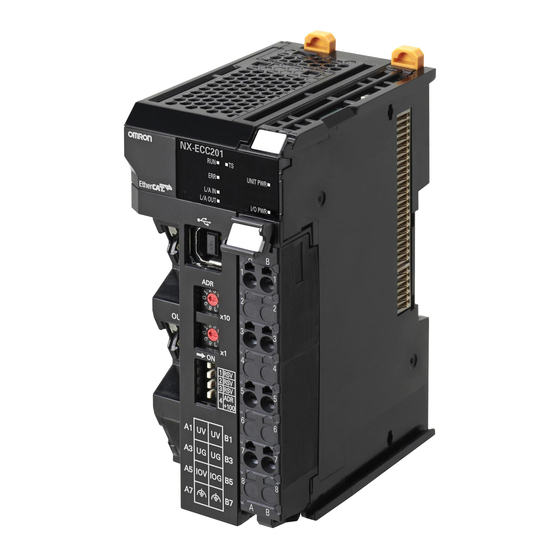
(G) Communications cable Support Software EtherCAT Slave Terminal Ethernet cables (B) NX Series Peripheral USB port EtherCAT Coupler Unit NX-ECC201 Connection to peripheral USB port on EtherCAT Coupler Unit .xml (D) End Cover (F) ESI files (C) NX Units 2 - 4... -
Page 51: A-7-1 Relationship Between The Unit Versions Of Ethercat Coupler Unit And Sysmac Studio
*1. A CPU Unit with unit version 1.05 or later is required to connect an EtherCAT Slave Terminal to the built-in EtherCAT port on an OMRON NJ-series CPU Unit. Refer to A-7-2 Relationship between Unit Versions of EtherCAT Coupler Unit and CPU Units on page A-59 for details. OMRON CJ1W-NC81/82 Position Control Units cannot be connected to the EtherCAT Slave Terminal even though they support EtherCAT. -
Page 52: Types Of Nx Units
Refer to the user’s manual for the specific Units for details. For information on the most recent lineup of NX Units, refer to NX-series catalogs or OMRON websites, or ask your OMRON representative. -
Page 53: Support Software
2 Features and System Configuration Support Software This section describes the Support Software that is used to set up the EtherCAT Slave Terminal. 2-3-1 Applicable Support Software This following Support Software can be used to set up the EtherCAT Slave Terminal. Support Software Version Sysmac Studio... - Page 54 2 Features and System Configuration Connection Procedures Refer to the NJ-Series Sysmac Studio Version 1 Operation Manual (Cat. No. W504) for details on placing the Sysmac Studio online. Going Online through the USB Port on the EtherCAT Coupler Unit ...
-
Page 55: Scope Of Access When Connected To The Usb Port On The Ethercat Coupler Unit
2 Features and System Configuration 2-3-3 Scope of Access When Connected to the USB Port on the Ether- CAT Coupler Unit The scope of access from the Sysmac Studio when it is connected to the USB port on the EtherCAT Coupler Unit is limited to the EtherCAT Slave Terminal at the connection. - Page 56 2 Features and System Configuration 2 - 10 NX-series EtherCAT Coupler Unit User’s Manual (W519)
-
Page 57: Specifications And Application Procedures
Specifications and Application Procedures This section provides the general specifications of the EtherCAT Slave Terminal, the specifications of the EtherCAT Coupler Unit and End Cover, and the applications pro- cedures for the EtherCAT Slave Terminal. 3-1 Specifications ..........3-2 3-1-1 General Specifications of EtherCAT Slave Terminals . -
Page 58: Specifications
*1. Refer to the NX-series Digital I/O Units User’s Manual (Cat. No. W521) for the vibration and shock resistance specifications of the Relay Output Unit. 3-1-2 EtherCAT Coupler Unit Specifications Item Specification Model NX-ECC201 Number of connectable NX 63 Units max. Units Communications protocol EtherCAT protocol Modulation... - Page 59 3 Specifications and Application Procedures Item Specification Transmission distance Distance between nodes: 100 m or less Input: 1,024 bytes max. (including input data, status, and unused areas) Send/receive PDO data sizes Output: 1,024 bytes max. (including output data and unused areas) Input: 256 bytes Mailbox data size Output: 256 bytes...
- Page 60 3 Specifications and Application Procedures Item Specification Installation orientation: 6 possible orientations Restrictions: • Used in the upright installation orientation. 10-W output, 40°C Output power [W] 8.5-W output, 55°C Installation orientation and 40 45 50 55 60 restrictions Ambient temperature [°C] •...
-
Page 61: End Cover Specifications
3 Specifications and Application Procedures Item Specification Through-wiring for unwired terminals. Unit power supply (24 VDC) Terminal arrangement I/O power supply (5 to 24 VDC) Ground to 100 Ω or less. Accessory End Cover (NX-END01): 1 *1. This specification applies to a connection to the built-in EtherCAT port on an NJ-series CPU Unit. *2. -
Page 62: Procedures
3 Specifications and Application Procedures Procedures 3-2-1 EtherCAT Slave Terminal Application Procedures Procedure Sections • 2-2-2 Types of NX Units on page • 3-1 Specifications on page 3-2 • Section 5 Designing the Power 1. Preparing for Work Supply System •... - Page 63 3 Specifications and Application Procedures • 9-3 Assigning Variables on page 9-29 • 9-3-2 Assigning Device Variables 6. Assigning Slave Terminal Variables to I/O Ports on page 9-30 • 9-3-4 Assigning Axis Variables on page 9-33 • NJ-series CPU Unit Software User’s Manual (W501) •...
-
Page 64: Details
3 Specifications and Application Procedures 3-2-2 Details Procedure Item Description Reference Preparing for Selecting NX • Select the NX Units for I/O refreshing methods, and the • 2-2-2 Types of Work Units quantity and types of I/O that are required. NX Units on page 2-6 •... - Page 65 3 Specifications and Application Procedures Procedure Item Description Reference Configuring the Slave Terminal Set up the Slave Terminal (create the configuration and set Slave Terminal and Making the Operation Set- the parameters) on the Edit Slave Terminal Configuration Tab Configuring and tings Page on the Sysmac Studio.
- Page 66 3 Specifications and Application Procedures Procedure Item Description Reference Turning ON Turning ON the Turn ON the Unit power supply to the EtherCAT Coupler Unit 4-2 Indicators on Power and Unit Power Sup- and to any Additional NX Unit Power Supply Units that are page 4-5 Going Online ply to the Slave...
- Page 67 3 Specifications and Application Procedures Procedure Item Description Reference Checking Indi- Checking Indi- Check the indicators on the NJ-series CPU Unit. 4-2 Indicators on cators cators page 4-5 EtherCAT Master • A flashing yellow EtherCAT LINK/ACT indicator shows that data is being transmitted and received after the link is established.
- Page 68 3 Specifications and Application Procedures 3 - 12 NX-series EtherCAT Coupler Unit User’s Manual (W519)
-
Page 69: Part Names And Functions
Part Names and Functions This section gives the names of the parts of the EtherCAT Coupler Unit, NX Units, and End Cover and describes the functions of the parts. 4-1 Parts and Names ..........4-2 4-1-1 EtherCAT Coupler Units . -
Page 70: Parts And Names
Function Marker attachment locations The locations where markers are attached. The markers made by OMRON are installed for the factory setting. Commercially available markers can also be installed. For details, refer to 6-1-8 Attaching Markers on page 6-17. Unit specifications The specifications of the Unit are given. -
Page 71: Nx Units
Name Function Marker attachment locations The locations where markers are attached. The markers made by OMRON are installed for the factory setting. Commercially available markers can also be installed. NX bus connector This connector is used to connect each Unit. -
Page 72: End Cover
4 Part Names and Functions 4-1-3 End Cover An NX-END01 End Cover is connected to the end of the EtherCAT Slave Terminal. One End Cover is provided together with the EtherCAT Coupler Unit. Letter Name Function Unit hookup guides These guides are used to connect the End Cover to the NX Unit on the left of the End Cover. -
Page 73: Indicators
4 Part Names and Functions Indicators This section describes the indicators on the EtherCAT Coupler Unit. TS Indicator The TS indicator shows the status of the EtherCAT Coupler Unit and the communications status between the EtherCAT Coupler Unit and the NX Units. Color Status Meaning... - Page 74 4 Part Names and Functions UNIT PWR Indicator The UNIT PWR indicator shows the status of the Unit power supply. Color Status Meaning Green Lit. Power is currently supplied from the Unit power supply. Not lit. No power is currently supplied. I/O PWR Indicator The I/O PWR indicator shows the status of the I/O power supply.
- Page 75 4 Part Names and Functions RUN Indicator The RUN indicator shows the operating status of EtherCAT communications for the EtherCAT Coupler Unit. Color Status Meaning Green Lit. Operational state Blinking Pre-Operational state Single flash Safe-Operational state Not lit. Init state For details on EtherCAT states, refer to 8-3 Transitions of Communications States on page 8-4.
- Page 76 4 Part Names and Functions Additional Information The timing of flashing and flickering of the indicators is shown below. 50 ms Flickering Blinking 200 ms 200 ms 1,000 ms Single flash 200 ms 200 ms 1,000 ms Double flash 200 ms 200 ms 200 ms 4 - 8 NX-series EtherCAT Coupler Unit User’s Manual (W519)
-
Page 77: Hardware Switch Settings
4 Part Names and Functions Hardware Switch Settings This section describes the functions of the hardware switches (i.e., the rotary switches and the DIP switch) on the front panel of the EtherCAT Coupler Unit. 4-3-1 Rotary Switches The rotary switches are used to set the node address of the EtherCAT Slave Terminal on the EtherCAT network. -
Page 78: Setting The Node Address
4 Part Names and Functions 4-3-3 Setting the Node Address You must set the node address to enable the EtherCAT master to recognize the EtherCAT Slave Termi- nal. There are two ways to set the node address: Switch settings and settings from the Sysmac Studio. The switch settings are used to select the method to use. -
Page 79: Communications Connector And Peripheral Usb Port
4 Part Names and Functions Communications Connector and Periph- eral USB Port This section provides the specifications of the communications connectors and peripheral USB port on the front panel of the EtherCAT Coupler Unit. Peripheral USB port Communications connectors Top: IN connector Bottom: OUT connector Communications Connectors Connect Ethernet cables to the communications connectors. -
Page 80: Terminal Block
4 Part Names and Functions Terminal Block The terminal block on the EtherCAT Coupler Unit is a removable screwless clamping terminal block that allows you to easily connect and remove the wiring. The Unit power supply, I/O power supply, and ground wire are connected to this screwless clamping terminal block. -
Page 81: Din Track Contact Plate
4 Part Names and Functions DIN Track Contact Plate There is a DIN Track contact plate in the section on the back of the EtherCAT Coupler Unit that comes into contact with the DIN Track. This plate is connected internally to the functional ground terminal on EtherCAT Coupler Unit. This means that the functional ground terminal will be electrically connected to the DIN Track. - Page 82 4 Part Names and Functions 4 - 14 NX-series EtherCAT Coupler Unit User’s Manual (W519)
-
Page 83: Designing The Power Supply System
Designing the Power Supply Sys- This section describes how to design the power supply system for the EtherCAT Slave Terminal. 5-1 Power Supply System and Design Concepts ..... . . 5-2 5-1-1 Power Supply System and Types of Power Supplies . -
Page 84: Power Supply System And Design Concepts
5 Designing the Power Supply System Power Supply System and Design Concepts This section describes the power supply system for an EtherCAT Slave Terminal and the design con- cepts. 5-1-1 Power Supply System and Types of Power Supplies Power Supply System Configuration Diagram An example of a power supply system configuration diagram for an EtherCAT Slave Terminal is shown below. -
Page 85: Nx-Series Power Supply-Related Units
For the specifications of NX-series power supply-related Units, refer to the NX-series System Units User’s Manual (Cat. No. W523). For information on the most recent lineup of NX Series power sup- ply-related Units, refer to NX-series catalogs or OMRON websites, or ask your OMRON representative. Unit name... - Page 86 5 Designing the Power Supply System Unit name Function Additional I/O Power Sup- This NX Unit provides additional I/O power supply. ply Unit Use this NX Unit in the following cases. (a) When the I/O power supply capacity is insufficient •...
-
Page 87: Design Concepts For Power Supply To The Ethercat Slave Terminal
5 Designing the Power Supply System Unit name Function I/O Power Supply Con- This NX Unit is used when there are not enough I/O power supply terminals for the nection Unit connected external devices that are connected to NX Units such as Digital I/O Units and Analog I/O Units. -
Page 88: Designing The Nx Unit Power Supply System
5 Designing the Power Supply System Designing the NX Unit Power Supply System This section describes how to design the NX Unit power supply to the EtherCAT Slave Terminal. 5-2-1 Procedure for Designing the NX Unit Power Supply System The total power consumption from the NX Unit power supply must not exceed the NX Unit power supply capacity of the Unit that supplies the NX Unit power. -
Page 89: Calculation Example For The Nx Unit Power Supply
Calculation Example for the NX Unit Power Supply This section provides a calculation example for the NX Unit power supply. Unit Configuration Example Name Model Quantity Power consumption/Unit EtherCAT Coupler Unit NX-ECC201 1.45 W Digital Input Unit NX-ID3317 0.5 W Relay Output Unit NX-OC2633 0.8 W ... - Page 90 5 Designing the Power Supply System Additional Information Excess or insufficiency in the NX Unit power supply capacity can be easily checked when the Unit configuration is created on the Edit Slave Terminal Configuration Tab Page on the Sysmac Studio. Use the following procedure to check the power supply capacity. On the Edit Slave Terminal Configuration Tab Page on the Sysmac Studio, select the Unit to supply NX Unit power.
-
Page 91: Designing The I/O Power Supply System
5 Designing the Power Supply System Designing the I/O Power Supply Sys- This section describes how to design the I/O power supply to the EtherCAT Slave Terminal. 5-3-1 I/O Power Supply Method There are the following two methods to supply the I/O power supply to the EtherCAT Slave Terminal depending on the type and model of the NX Units. -
Page 92: Designing The I/O Power Supply From The Nx Bus
5 Designing the Power Supply System 5-3-2 Designing the I/O Power Supply from the NX Bus Procedure for Designing the I/O Power Supply Make sure that the following design conditions are met when you design the I/O power supply from the NX bus. - Page 93 5 Designing the Power Supply System ●The total current consumption ●The total current consumption from the I/O power supply from the I/O power supply ●The total current consumption from the I/O must not exceed the must not exceed the power supply must not exceed the maximum current of the I/O maximum current of the I/O power supply.
- Page 94 5 Designing the Power Supply System Maximum I/O Power Supply Current The maximum I/O power supply current is the maximum current that the I/O power supply that is connected to the EtherCAT Coupler Unit or Additional I/O Power Supply Unit can supply through the NX bus connectors to the NX Units.
- Page 95 5 Designing the Power Supply System Calculating the Voltage Drop in the I/O Power Supply Voltage drop occurs in the EtherCAT Slave Terminal due to the contact resistance at the points where Units are connected to each other. Design the I/O power supply system to maintain the voltage specifi- cations of the NX Unit I/O circuits and connected external devices even if the voltage of the I/O power supply drops.
-
Page 96: Designing The I/O Power Supply From External Sources
5 Designing the Power Supply System Procedure Use the following formula to calculate the total current consumption from the I/O power supply. Total current consumption from the I/O power supply =(1) + (2) + (3) + (4) + (5) + (6) + (7) = 0 A + 1.5 A + 1.5 A + 0 A + 0 A + 0.5 A + 0.5 A = 4 A Find the I/O power supply voltage and make sure that it is within the voltage specifications of the... -
Page 97: Selecting External Power Supplies And Protective Devices
• Has double or reinforced insulation between the input and output. • Has an output voltage of 24 VDC (20.4 to 28.8 VDC). Recommended Power Supplies: S8JX Series (manufactured by OMRON) Calculating the Required Power Supply Capacity of the Unit Power Supply ... - Page 98 This section provides a calculation example for the configuration example that is given in 5-2-2 Cal- culation Example for the NX Unit Power Supply on page 5-7. Name Model Quantity Power consumption/Unit EtherCAT Coupler Unit NX-ECC201 1.45 W Digital Input Unit NX-ID3317 0.5 W Relay Output Unit NX-OC2633 0.8 W...
-
Page 99: Selecting The I/O Power Supplies
*1. Use an output voltage that is appropriate for the I/O circuits of the NX Units and the connected external devices. Recommended Power Supplies: S8JX Series (manufactured by OMRON) Calculating the Required Power Supply Capacity of the I/O Power Supply... - Page 100 5 Designing the Power Supply System 5 - 18 NX-series EtherCAT Coupler Unit User’s Manual (W519)
-
Page 101: Installation
Installation This section describes how to install the EtherCAT Slave Terminal. 6-1 Installing Units ..........6-2 6-1-1 Installation Precautions . -
Page 102: Installing Units
6 Installation Installing Units This section describes how to mount Units to an EtherCAT Slave Terminal. 6-1-1 Installation Precautions To increase the reliability of the EtherCAT Slave Terminal and take complete advantage of its function- ality, observe the following precautions. Installation Location Do not install the EtherCAT Slave Terminal in the following locations. - Page 103 6 Installation Control panel EtherCAT Slave Terminal Louver Accessibility for Operation and Maintenance • To ensure safe access for operation and maintenance, separate the EtherCAT Slave Terminal as much as possible from high-voltage equipment and power machinery. • If will be easy to operate the EtherCAT Slave Terminal if it is mounted at a height of 1.0 to 1.6 m above the floor.
- Page 104 6 Installation Wiring Ducts Whenever possible, route I/O wiring through wiring ducts. Install mounting bases so that it is easy to wire the I/O Units through ducts. It is handy to have the ducts at the same height as the EtherCAT Slave Terminal. Duct 20 mm min.
- Page 105 6 Installation Routing Wiring Ducts Install the wiring ducts at least 20 mm away from the tops of the devices and any other objects (e.g., top of the panel, other wiring ducts, structural supports, and components) to provide enough space for air circulation and replacement of Units.
-
Page 106: Preparations For Installation
You must install the EtherCAT Coupler Unit and NX Units on a DIN Track. The following products are recommended. Name Model Manufacturer Remarks 35-mm DIN PFP-50N OMRON Corporation • Length: 50 cm Track • Material: Aluminum • Surface treatment: Insulated PFP-100N OMRON Corporation • Length: 100 cm •... - Page 107 6 Installation DIN Tracks PFP-100N/50N DIN Track 7.3±0.15 35±0.3 27±0.15 15(5) 1000(500)* *1 PFP-50N dimensions are given in parentheses. NS 35/7,5 PERF R0.8 R0.8 NS 35/15 PERF 15° R1.25 R1.25 End Plate PFP-M (Two) CLIPFIX 35 (Two) 6 - 7 NX-series EtherCAT Coupler Unit User’s Manual (W519)
-
Page 108: Installation Orientation
6 Installation 6-1-3 Installation Orientation An EtherCAT Slave Terminal can be installed in any of the following six orientations. (A) is the upright installation direction and (B) to (F) are installation directions other than upright. Down However, there are restrictions on the installation orientation of the EtherCAT Coupler Unit due to the ambient operating temperature and the NX Unit power supply capacity. -
Page 109: Installing The Ethercat Coupler Unit
6 Installation 6-1-4 Installing the EtherCAT Coupler Unit This section describes how to install the EtherCAT Coupler Unit. Precautions for Safe Use • Always turn OFF the power supply before installing the Unit. If the power supply is not OFF, the Unit may malfunction or may be damaged. •... - Page 110 6 Installation • Using an NS 35/7,5 PERF or NS 35/15 PERF DIN Track Use one M6 screw for each four holes in the DIN Track. There must be a screw for each interval of 100 mm or less. The screw tightening torque is 5.2 N·m. DIN Track Use one screw for each four holes.
-
Page 111: Installing And Connecting Nx Units
6 Installation Press the EtherCAT Coupler Unit firmly against the DIN Track until you hear the DIN Track mounting hook lock into place. After you mount the EtherCAT Coupler Unit, check to be sure that it is securely mounted on the DIN Track. - Page 112 6 Installation Precautions for Correct Use • When you mount an NX Unit to the EtherCAT Coupler Unit or when you connect NX Units to each other, always mount the Units one at a time on the DIN Track. If you connect NX Units to each other and attempt to mount them together to the DIN Track at the same time, the Units may separate from each other and fall.
- Page 113 6 Installation Mounting an NX Unit to the EtherCAT Coupler Unit From the front of the EtherCAT Coupler Unit, engage the Unit hookup guides on the NX Unit with the Unit hookup guides on the EtherCAT Coupler Unit. Unit hookup guides Unit hookup guides Slide the NX Unit in on the hookup guides.
- Page 114 6 Installation Mounting NX Units to Each Other Use the following procedure to mount NX Units to each other. From the front of the previously mounted NX Unit, engage the Unit hookup guides on a new Unit with the Unit hookup guides on the previously mounted NX Unit. Unit hookup guides Unit hookup guides Slide the NX Unit in on the hookup guides.
-
Page 115: Mounting The End Cover
6 Installation 6-1-6 Mounting the End Cover Always mount an End Cover to the end of the Slave Terminal. Precautions for Safe Use • Always turn OFF the power supply before mounting the End Cover. If the power supply is not OFF, the Unit may malfunction or may be damaged. -
Page 116: Mounting The End Plates
After you mount the End Cover, secure the EtherCAT Slave Terminal with End Plates. Using PFP-M (OMRON) To mount an End Plate, 1) hook the bottom of it on the bottom of the DIN Track and 2) rotate the End Plate to hook the top of it on the top of the DIN Track. -
Page 117: Attaching Markers
Markers can be attached to EtherCAT Coupler Units, NX Units, and terminal blocks on NX Units to identify them. The plastic markers made by OMRON are installed for the factory setting. The ID information can be written on them. Commercially available markers can also be installed. -
Page 118: Removing Units
6 Installation 6-1-9 Removing Units Precautions for Safe Use Always turn OFF the power supply before removing any Unit. If the power supply is not OFF, the Unit may malfunction or may be damaged. Precautions for Correct Use • When removing an NX Unit, remove multiple Units together which include the one you want to remove. - Page 119 6 Installation Remove the Unit with either (a) or (b) below. (a) For an EtherCAT Coupler Unit, place your fingers on the protrusions on the EtherCAT Cou- pler Unit and pull it straight forward. (b) For an NX Unit, place your fingers on the protrusions on more than one NX Unit, including the NX Unit to remove, and pull the NX Units straight forward.
-
Page 120: Assembled Appearance And Dimensions
6 Installation 6-1-10 Assembled Appearance and Dimensions Installation Dimensions End Cover EtherCAT Coupler Unit End Plate NX Units End Plate DIN Track 104.5 65.2 W+(C)+(C) (Unit: mm) (Unit: mm) W: Width of the EtherCAT Slave Terminal W + (C) + (C): Width of the EtherCAT Slave Terminal including the End Plates Dimension from the DIN Track model DIN Track dimension... - Page 121 The widths of the Units in the example EtherCAT Slave Terminal configuration and the total configu- ration width are given below. Name Model Unit width EtherCAT Coupler Unit NX-ECC201 46 mm NX Units: Digital Input Units NX-ID3317 12 mm × 4 Units NX Units: Temperature Input Units NX-TS3101 24 mm ×...
- Page 122 6 Installation Installation Height The installation height of the EtherCAT Slave Terminal depends on the model of DIN Track and on the models of NX Units that are mounted. Also, additional space is required for the cables that are connected to the Unit. Allow sufficient depth in the control panel and allow extra space when you mount the EtherCAT Slave Terminal.
-
Page 123: Control Panel Installation
6 Installation Control Panel Installation To ensure system reliability and safety, the system must be designed and configured according to the installation environment (temperature, humidity, vibration, shock, corrosive gases, overcurrent, noise, etc.). 6-2-1 Temperature Panels have been reduced in size due to space-saving and miniaturization in devices and systems, and the temperature inside the panel may be at least 10 to 15°C higher than outside the panel. - Page 124 6 Installation Forced Ventilation by Fan at Top of Panel EtherCAT Slave Terminal EtherCAT Slave Terminal Air filter Forced Ventilation Method Forced Air Circulation by Fan in Closed Panel EtherCAT Slave Terminal EtherCAT Slave Terminal Forced Circulation Method ...
-
Page 125: Humidity
6 Installation 6-2-2 Humidity Rapid temperature changes can cause condensation to occur, resulting in malfunctioning due to short-circuiting. When there is a possibility of this occurring, take measures against condensation, such as leaving the EtherCAT Slave Terminal power ON at night or installing a heater in the control panel to keep it warmer. Control panel Moisture absorber... -
Page 126: Electrical Environment
6 Installation 6-2-5 Electrical Environment When installing or wiring devices, make sure that there will be no danger to people and that noise will not interfere with electrical signals. Installation Location of EtherCAT Slave Terminals Install the EtherCAT Slave Terminal as far away as possible from high-voltage (600 V or higher) and power devices to ensure safe operation and maintenance. - Page 127 6 Installation Arrangement of EtherCAT Slave Terminal and Cables Observe the following points. • The coils and contacts in electromagnetic contactors and relays in an external circuit are sources of noise. Do not install them close to the EtherCAT Slave Terminal. Locate them at least 100 mm away from the EtherCAT Slave Terminal.
- Page 128 6 Installation Supplying I/O Power from External Sources Power circuits Power supply for general operations circuits Power supply for input circuits of EtherCAT Slave Terminal Power supply for output circuits of EtherCAT Slave Terminal Noise Unit power supply for EtherCAT Slave Terminal filter Outlet (for peripheral devices) Power Supply System Diagram...
- Page 129 6 Installation • If noise causes malfunctions, use countermeasures, such as CR surge absorbers and diodes, for noise sources of input devices and output load devices, as required. External Wiring Wiring, and noise countermeasures in particular, are based on experience, and it is necessary to closely manage wiring based on experience and information in the manuals.
- Page 130 6 Installation • To avoid overheating the conduits when using conduits for wiring, do not place wires for a single circuit in separate conduits. Power supply Conduits Load Incorrect Power supply Conduits Load Correct Power supply Conduits Load Correct Parallel Wiring (Single Phase) •...
-
Page 131: Grounding
6 Installation 6-2-6 Grounding Grounding has the following two purposes. • Protective Grounding Protective grounding is done to ensure safety. It is intended to prevent electrical shock by grounding the electrical potential that is generated by factors such as leakage, induction, or failure. •... - Page 132 6 Installation If the DIN Track is made of steel and the surface is not treated to produce an insulating material, you can omit grounding the functional ground terminal on any Unit that has one, as shown in the following figures.
-
Page 133: Wiring
Wiring This section describes how to wire the EtherCAT Slave Terminal. 7-1 EtherCAT Network Wiring ........7-2 7-1-1 Installation Precautions . -
Page 134: Ethercat Network Wiring
7 Wiring EtherCAT Network Wiring This section describes how to install the EtherCAT network. 7-1-1 Installation Precautions Basic precautions for the installation of EtherCAT networks are provided below. Precautions when Installing a Network • When you install an EtherCAT network, take sufficient safety precautions and perform the installation according to all applicable standards and specifications. -
Page 135: Preparations For Installation
Recommended products are given in the following tables. Cables with Connectors Sizes and Conductor Pairs: AWG 22 × 2 Pairs Product name Manufacturer Model Length (m) Cables with Connectors OMRON Corporation XS5W-T421-AMD-K on Both Ends XS5W-T421-BMD-K (RJ45/RJ45) XS5W-T421-CMD-K XS5W-T421-DMD-K XS5W-T421-GMD-K... -
Page 136: Pin Arrangement Of Communications Connectors On The Ethercat Coupler Unit
Kuramo Electric Co., Ltd. KETH-PSB-OMR Nihon Electric Wire & Cable Co., Ltd. PNET/B RJ45 Assembly Connectors OMRON Corporation XS6G-T421-1 *1. We recommend that you use combinations of the above Cables and Connectors. Precautions for Correct Use • The maximum length between nodes is 100 m. However, some cables are specified for less than 100 m. -
Page 137: Connecting Communications Cables And Connectors
7 Wiring 7-1-4 Connecting Communications Cables and Connectors Use straight connections for the communications cables and connectors, as shown below. Wire color Wire color Pin No. Pin No. White-Green White-Green Green Green White-Orange White-Orange Blue Blue White-Blue White-Blue Orange Orange White-Brown White-Brown Brown... -
Page 138: Connecting Communications Cables
7 Wiring 7-1-5 Connecting Communications Cables Cable connections can be made freely in EtherCAT networks. The following example shows daisy-chain connections. Connect the communications cable from the EtherCAT master to the input port on the first EtherCAT Slave Terminal, and then connect another communications cable from the output port on the first Ether- CAT Slave Terminal to the input port on the next EtherCAT Slave Terminal. - Page 139 7 Wiring Additional Information • Make sure the cable between each pair of devices connects an output port to an input port. Normal communications are not possible if an output port is connected to another output port or an input port is connected to another input port. •...
-
Page 140: Connecting The Power Supply And Ground Wires
7 Wiring Connecting the Power Supply and Ground Wires This section describes how to wire the power supplies and ground the EtherCAT Slave Terminal. 7-2-1 Wiring the EtherCAT Coupler Unit The wiring of the power supply and ground to the EtherCAT Coupler Unit is shown in the following fig- ure. -
Page 141: Wiring The Power Supply To The Ethercat Slave Terminal
7 Wiring Functional Ground Terminals These are the functional ground terminals. Connect the ground wire to one of these terminals. The details are given in the following table. Terminal number indication Terminal symbol Description A7 or B7 Connect the ground wire to either the A7 or B7 ter- minal. - Page 142 7 Wiring DIN Track Contact Plates A Unit that has a ground terminal also has a DIN Track contact plate on the back of the Unit. Unit side Ground terminal DIN Track contact plate Connected inside the Unit. The DIN Track contact plate is connected internally to the ground terminal on the Unit. This means that the ground terminal will be electrically connected to the DIN Track.
- Page 143 7 Wiring If the DIN Track is made of steel and the surface is not treated to produce an insulating material, you can omit grounding the functional ground terminal on any Unit that has one, as shown in the following figures.
- Page 144 If the ground wire for the EtherCAT Coupler Unit or an NX Unit with a ground terminal is shared with power equipment, noise will adversely affect the Units. You can use OMRON NX-AUX01 DIN Track Insulation Spacers with PFP-50N or PFP-100N DIN Tracks to isolate an EtherCAT Slave Terminal from the control panel.
-
Page 145: Precautions For Wiring The Ethercat Slave Terminal Together With Computers And Other Peripheral Devices
7 Wiring 7-2-4 Precautions for Wiring the EtherCAT Slave Terminal Together with Computers and other Peripheral Devices Caution When you connect a computer or other peripheral device to the following Unit, either ground the 0-V side of the external power supply (i.e. Unit power supply) or do not ground it at all. •... -
Page 146: Wiring To The Screwless Clamping Terminal Block
7 Wiring 7-2-5 Wiring to the Screwless Clamping Terminal Block This section describes how to connect wires to the screwless clamping terminal block on the EtherCAT Coupler Unit, the installation and removing methods, and functions for preventing incorrect attachment. You can connect ferrules that are attached to the twisted wires to the screwless clamping terminal block. - Page 147 7 Wiring Applica- ble wire Terminal Manufac- Ferrule Crimping tool types turer model (AWG)) Terminals Phoenix AI0,34-8 0.34 (#22) Phoenix Contact (The figure in parentheses is the other than Contact applicable wire size.) AI0,5-8 0.5 (#20) ground ter- AI0,5-10 CRIMPFOX 6 (0.25 to 6 mm , AWG24 to 10) minals AI0,75-8...
- Page 148 7 Wiring Conductor length (stripping length) Precautions for Correct Use • Use cables with suitable wire sizes for the carrying current. There are also restrictions on the current due to the ambient temperature. Refer to the manuals for the cables and use the cables correctly for the operating environment.
- Page 149 7 Wiring Recommended screwdriver Model Manufacturer SZF0 Phoenix Contact Connecting Ferrules Insert the ferrule straight into the terminal hole. It is not necessary to press a flat-blade screwdriver into the release hole. Ferrule After you make a connection, make sure that the ferrule is securely connected to the terminal block. ...
- Page 150 7 Wiring Remove the flat-blade screwdriver from the release hole. After you make a connection, make sure that the twisted wire or the solid wire is securely connected to the terminal block. Precautions for Safe Use • Do not press the flat-blade screwdriver straight into the release hole. Doing so may break the terminal block.
- Page 151 7 Wiring Removing Wires Use the following procedure to remove the wires from the terminal block. The removal method is the same for ferrules, twisted wires, and solid wires. Press the flat-blade screwdriver diagonally into the release hole. Press at an angle of 10° to 15°. If you press in the screwdriver correctly, you will feel the spring in the release hole.
- Page 152 7 Wiring Precautions for Safe Use • Do not press the flat-blade screwdriver straight into the release hole. Doing so may break the terminal block. • When you insert a flat-blade screwdriver into a release hole, press it down with a force of 30 N max.
- Page 153 7 Wiring Removing a Terminal Block Press the lock lever on the terminal block and pull out the top of the terminal block to remove it. Lock lever Terminal block Attaching a Terminal Block Mount the terminal block hook on the guide at the bottom of the EtherCAT Coupler Unit and press in on the top of the terminal block to attach it.
- Page 154 7 Wiring Preventing Incorrect Attachment of Terminal Blocks In order to prevent unintentionally installing the wrong terminal block, you can limit the combination of a Unit and a terminal block. Insert three Coding Pins (NX-AUX02) into three of the six incorrect attachment prevention holes on the Unit and on the terminal block.
- Page 155 1 through 6 in the figure below. As shown in the following table, there are 20 unique pin patterns that can be used. Unit Terminal Block Holes used by Holes used by OMRON OMRON Holes for incorrect Holes for incorrect attachment prevention attachment prevention...
- Page 156 Precautions for Correct Use OMRON uses the holes other than No. 1 to 6 in the figure on the previous page. If you insert a Coding Pin into one of the holes used by OMRON on the terminal block side, this makes it impossible to mount the terminal block on a Unit.
- Page 157 7 Wiring Unit 7 - 25 NX-series EtherCAT Coupler Unit User’s Manual (W519)
-
Page 158: Connecting Usb Cable
7 Wiring Connecting USB Cable The EtherCAT Coupler Unit can be connected directly to a computer in which the Sysmac Studio is installed through a USB cable. Connection Method Use a commercially available USB cable to connect the computer in which the Sysmac Studio is installed to the peripheral USB port on the EtherCAT Coupler Unit. - Page 159 7 Wiring Setting Up With the Sysmac Studio The connection between the EtherCAT Coupler Unit and computer is set up with the Sysmac Studio. Refer to 2-3-2 Connection Method and Procedures on page 2-7 for the procedure to connect to the Sysmac Studio.
-
Page 160: Wiring External Signal Lines
7 Wiring Wiring External Signal Lines Refer to the sections on wiring in the user’s manuals for individual NX Units for information on wiring the external I/O signal lines between the external devices and the NX Units. For precautions on wiring in control panels, refer to 6-2 Control Panel Installation on page 6-23. 7 - 28 NX-series EtherCAT Coupler Unit User’s Manual (W519) -
Page 161: Ethercat Communications
EtherCAT Communications This section provides an introduction to EtherCAT communications. 8-1 Structure of CAN Application Protocol over EtherCAT (CoE) ..8-2 8-2 EtherCAT Slave Information Files (ESI Files) ..... . . 8-3 8-3 Transitions of Communications States . -
Page 162: Structure Of Can Application Protocol Over Ethercat (Coe)
8 EtherCAT Communications Structure of CAN Application Proto- col over EtherCAT (CoE) EtherCAT allows the use of multiple protocols for communications. However, the EtherCAT Slave Ter- minal uses the CAN application protocol over EtherCAT (CoE) as the device profile for the CAN appli- cation protocol. -
Page 163: Ethercat Slave Information Files (Esi Files)
ESI files for the EtherCAT Coupler Unit and NX Units can be downloaded from the OMRON website. *1. Installation of the ESI files is not necessary if you are using the Sysmac Studio. The ESI files for OMRON EtherCAT slaves are already installed in the Sysmac Studio. You can update the Sysmac Studio to get the ESI files for the most recent models. -
Page 164: Transitions Of Communications States
8 EtherCAT Communications Transitions of Communications States The state transition model for communications control of the EtherCAT Slave Terminals is controlled by the EtherCAT master. The following figure shows the communications state transitions from when the power supply is turned Power supply ON Init Pre-Operational... -
Page 165: Process Data Objects (Pdos)
8 EtherCAT Communications Process Data Objects (PDOs) 8-4-1 Introduction Process data objects (PDOs) are used to transfer data during cyclic communications in realtime. There are two types of process data objects (PDOs): the RxPDOs, which are used by the EtherCAT Slave Terminal to receive data from the EtherCAT master;... -
Page 166: Pdo Mappings
8 EtherCAT Communications 8-4-2 PDO Mappings PDO mapping objects contain the I/O data for the EtherCAT Slave Terminals. PDO mapping objects for the RxPDOs are managed in the object dictionary from indexes 1600 to 17FF hex, and for the TxPDOs from indexes 1A00 to 1BFF hex. - Page 167 8 EtherCAT Communications In the previous example, a single application object is assigned to the PDO at index 1BFF hex (name: 512th transmit PDO mapping). This PDO is a TxPDO. The application object contains the Sysmac error status at index 2001 hex and subindex 01 hex. ...
-
Page 168: Assigning Pdos
8 EtherCAT Communications 8-4-3 Assigning PDOs Scheme for Assigning PDOs to EtherCAT Slaves You can assign more than one PDO to an EtherCAT slave. Here, PDOs are assigned to index 1C12 hex for the RxPDO, and 1C13 hex for the TxPDO. The following example shows how PDOs are assigned. -
Page 169: Service Data Objects (Sdos)
8 EtherCAT Communications Service Data Objects (SDOs) 8-5-1 Introduction EtherCAT Slave Terminals support SDO communications. The EtherCAT master can read and write data from and to entries in the object dictionary with SDO communications to make parameter settings and monitor status. Refer to A-5 CoE Objects on page A-13 for the objects that you can use with SDO communications. -
Page 170: Communications Between An Ethercat Master And Slaves
8 EtherCAT Communications Communications between an Ether- CAT Master and Slaves This section describes the communications modes between the master and slaves for EtherCAT com- munications, and the communications modes for EtherCAT Slave Terminals. 8-6-1 Communications Modes for Communications between an Ether- CAT Master and Slaves Free-Run Mode In this mode, the slave processes the I/O (i.e., refreshes the I/O data) asynchronous to the communica-... -
Page 171: Setting Up Slave Terminals
Setting Up Slave Terminals This section describes the procedures used to set up Slave Terminals. 9-1 Settings and Setting Procedures ....... . . 9-2 9-1-1 Items to Set . -
Page 172: Settings And Setting Procedures
9 Setting Up Slave Terminals Settings and Setting Procedures This section describes the settings that are required to access I/O data in EtherCAT Slave Terminals from an NJ-series CPU Unit. This section also describes the setting procedures. 9-1-1 Items to Set The settings that are used to access I/O data in the EtherCAT Slave Terminals from the NJ-series CPU Unit are given below. -
Page 173: Variable Assignment Settings
9 Setting Up Slave Terminals Setting Description Slave Ter- Configu- Unit configuration infor- This information describes the Unit configuration of the Slave minal con- ration mation Terminal. figuration informa- I/O allocation informa- This information specifies what I/O data in the Units in the and opera- tion tion... -
Page 174: Setting Slave Terminal Parameters
9 Setting Up Slave Terminals Setting Slave Terminal Parameters This section describes how to set the EtherCAT Slave Terminal parameters. 9-2-1 Items to Set There are the following two types of parameters that must be set in the EtherCAT Slave Terminals. Setting location on Sysmac Setting Description... - Page 175 9 Setting Up Slave Terminals Slave Terminal Configuring and Operation Settings These settings are used to control the Units in the Slave Terminal. Create the Unit Configuration of the Slave Terminal, and set up each Unit. Make the settings on the Edit Slave Terminal Configuration Tab Page on the Sysmac Studio. The Slave Terminal has the following setting information.
-
Page 176: Settings As An Ethercat Slave
9 Setting Up Slave Terminals 9-2-2 Settings as an EtherCAT Slave Register the EtherCAT Coupler Unit in the EtherCAT network and set the node address and other set- tings. Settings as an EtherCAT Slave The parameters of the EtherCAT Coupler Unit as an EtherCAT slave are given below. You can set only the items that have “Yes”... - Page 177 9 Setting Up Slave Terminals Settings Settable Description Slave Terminal These settings are for the Slave Terminal. Click the Edit Slave Terminal Config- Configuration uration Button to edit these parameters. *1. Register Slave Terminals that are not installed on the EtherCAT network but are scheduled for addition at a later date as disabled Slave Terminals.
-
Page 178: Setting The Unit Configuration Information
Model name This is the model of the EtherCAT Coupler Unit. NX-ECC201 Product name This is the product name. EtherCAT Cou- pler Unit version This is the Unit version of the EtherCAT Coupler Unit. - Page 179 9 Setting Up Slave Terminals Setta- Data Setting Description Default range NX Unit Mounting This setting enables or disables the mounting of an NX Setting Unit. You cannot directly edit these settings in the EtherCAT Coupler Unit. Serial Number This is the serial number of the EtherCAT Coupler Unit. You can get the serial number to set the serial number of the actual EtherCAT Coupler Unit.
- Page 180 9 Setting Up Slave Terminals NX Units Data Name Settable Description Default range Device name The name of the NX Unit. N* (Where * is a serial number from 1) Model name This is the model number of the NX Unit. Product name This is the product name.
-
Page 181: I/O Allocation Information
9 Setting Up Slave Terminals Click the Edit Slave Terminal Configuration Button next to Slave Terminal Configuration in the slave parameters for the EtherCAT Coupler Unit. The Edit Slave Terminal Configuration Tab Page is displayed. Drag the NX Unit from the Toolbox to the Edit Configuration Pane and drop it on the Slave Ter- minal. - Page 182 9 Setting Up Slave Terminals Precautions for Correct Use • If you turn ON the power to an EtherCAT Slave Terminal before you create or transfer the Unit configuration information to the Slave Terminal, the TS indicator on the front panel of the EtherCAT Coupler Unit will flash green at 0.5-second intervals.
-
Page 183: I/O Allocation Information
9 Setting Up Slave Terminals 9-2-4 I/O Allocation Information The I/O allocation information tells what I/O data in the EtherCAT Coupler Unit and the NX Units to exchange with process data communications. The EtherCAT Slave Terminal performs process data communications with the EtherCAT master based on the I/O allocation information. - Page 184 9 Setting Up Slave Terminals Registering I/O Entries The I/O data assigned to an I/O entry mapping is called an I/O entry. Default values are assigned to the I/O entries in each I/O entry mapping. Some I/O entry mappings allow you to add or delete I/O entries.
- Page 185 9 Setting Up Slave Terminals I/O Data Allocatable to I/O Entry Mappings The following I/O data can be registered as I/O entries for the I/O entry mappings. You can improve communications performance by selecting the status for the number of NX Units that are used.
- Page 186 9 Setting Up Slave Terminals NX object I/O entry Regis- Subin- mapping Data name Function Data type Default I/O port name tered by Index name default number number 505th Time Stamp of Syn- This time stamp tells ULINT Timestamp of 200A hex 01 hex Transmit...
- Page 187 9 Setting Up Slave Terminals NX Unit Message Enabled Status Data name Description NX Unit Message Enabled This status tells whether the NX Units can process message communications. Status 15 The status is acquired for as many NX Units as the numeric suffix at the end of NX Unit Message Enabled the data name.
- Page 188 9 Setting Up Slave Terminals NX Unit Error Status Data name Description NX Unit Error Status 15 This status tells whether an error exists on the NX Units. NX Unit Error Status 31 The status is acquired for as many NX Units as the numeric suffix at the end of NX Unit Error Status 63 the data name.
- Page 189 9 Setting Up Slave Terminals Sysmac Error Status Data name Description Sysmac Error Status This status gives the Sysmac error status for the EtherCAT Slave Terminal. This is an OR of the error status of the EtherCAT Coupler Unit and NX Units. TRUE: An error of the corresponding level exists.
- Page 190 9 Setting Up Slave Terminals Editing the I/O Allocation Settings You can edit the I/O allocations for the EtherCAT Coupler Unit and NX Units as necessary. In the Unit Settings Pane, click the Edit I/O Allocation Settings Button. The Edit I/O Allocation Settings Pane is displayed over the Edit Slave Terminal Configuration Tab Page.
- Page 191 9 Setting Up Slave Terminals Name/Label Description I/O Entry Map- This is a mapping list of the I/O entries in the corresponding Unit. ping List The I/O entry mapping list shows up to four inputs and outputs respectively. The I/O entry mapping list shows the following items. •...
- Page 192 9 Setting Up Slave Terminals Click the Add I/O Entry Button. The Add I/O Entry Dialog Box is displayed. A list similar to the one that is shown below is displayed. This list shows the I/O data that you can add to the selected I/O entry mapping list. Select the I/O data to add, and then click the OK Button.
-
Page 193: Unit Operation Settings
9 Setting Up Slave Terminals 9-2-5 Unit Operation Settings Unit Operation Settings for the EtherCAT Coupler Unit The operation settings of the EtherCAT Coupler Unit are listed below. Setting Setting range Default Description Synchronization 0 to 600 s (0 implies A Synchronization Interruption Error occurs Error Setting 120 s.) - Page 194 9 Setting Up Slave Terminals Editing the Unit Operation Settings You can edit the Unit operation settings for the EtherCAT Coupler Unit and NX Units as necessary. In the Unit Settings Pane, click the Edit Unit Operation Settings Button. The Edit Unit Operations Settings Tab Page is displayed. Change the set value of each setting.
-
Page 195: Unit Application Data
9 Setting Up Slave Terminals 9-2-6 Unit Application Data The Unit application data is the data that enables the functionality that is specific to each NX Unit. Not all NX Units have Unit application data. Refer to the manual for NX Units that have Unit application data for the method to set and transfer Unit application data. - Page 196 9 Setting Up Slave Terminals Precautions for Correct Use You can read only the Unit configuration in the Slave Terminal by comparing and merging with the actual Unit configuration. You cannot read the I/O allocation information, Unit operation set- tings, and Unit application data. Getting NX Unit Serial Numbers If the serial number check method that is set in the EtherCAT Coupler Unit is set to Setting = Actual device, you must download the Unit configuration information in which the serial numbers for the NX...
- Page 197 9 Setting Up Slave Terminals Exporting/Importing Slave Terminal Settings and NX Unit Settings You can export and import the Slave Terminal settings and NX Unit settings as files. Exporting/Importing Settings for the EtherCAT Coupler Unit as an EtherCAT Slave On the EtherCAT Configuration Edit Tab Page, you can export all of the Slave Terminal settings, shown below, into a single file (extension .ets).
- Page 198 9 Setting Up Slave Terminals Exporting/Importing NX Unit Settings On the Edit Slave Terminal Configuration Tab Page, you can export the Unit operating settings and Unit application data for each NX Unit into a single file (extension .nsf). The exported NX Unit setting file can be imported to add other NX Units with the same settings. To do this, go into the Edit Slave Terminal Configuration Tab Page in a new project or the same project on the Sysmac Studio.
-
Page 199: Assigning Variables
9 Setting Up Slave Terminals Assigning Variables This section describes how to assign variables in the NJ-series CPU Unit to the I/O data in the Ether- CAT Slave Terminal. 9-3-1 Methods to Assign Variables The methods that are used to assign variables in the NJ-series CPU Unit to I/O data in the Slave Termi- nal are given below. -
Page 200: Assigning Device Variables To I/O Ports
9 Setting Up Slave Terminals 9-3-2 Assigning Device Variables to I/O Ports When you create the Unit configuration information, the I/O data of the NX Units mounted in the Slave Terminal are displayed as I/O ports. To access the EtherCAT Slave Terminal, assign device variables to the I/O ports and reference the device variables in the user program. - Page 201 9 Setting Up Slave Terminals Registering Device Variables and Attributes Registering Device Variables You assign device variables to I/O ports in the I/O Map of the Sysmac Studio. The device variables that you create are registered in the variable table. ...
-
Page 202: I/O Ports For Status That Accept Device Variable Assignments
9 Setting Up Slave Terminals 9-3-3 I/O Ports for Status That Accept Device Variable Assignments I/O Ports for Status To access the status of the EtherCAT Slave Terminal from the user program in the NJ-series CPU Unit, assign devices variables to the I/O ports for the status. Refer to Allocatable I/O Data in an EtherCAT Coupler Unit on page 9-14 under 9-2-4 I/O Allocation Information on page 9-13 for the I/O ports that you can assign. -
Page 203: Assigning Axis Variables
9 Setting Up Slave Terminals 9-3-4 Assigning Axis Variables To control NX Units, such as Position Interface Units, with the Motion Control Function Module, create axes on the Sysmac Studio, and assign system-defined variables called Axis Variables to the I/O data. Refer to the NX-series Position Interface Unit User’s Manual (Cat. -
Page 204: Transferring And Comparing Settings
9 Setting Up Slave Terminals Transferring and Comparing Settings This section describes how to transfer and compare EtherCAT Slave Terminal settings that you set on the Sysmac Studio. WARNING Always confirm safety at the destination node before you transfer Unit configuration information, parameters, settings, or other data from tools such as the Sysmac Studio. - Page 205 9 Setting Up Slave Terminals To transfer the Unit operation settings for the EtherCAT Slave Terminal and the application data for the NX Units, clear the selections of the following check boxes on the Synchronization Pane. These items are not transferred (none of these items are synchronized). •...
-
Page 206: Comparing Settings
9 Setting Up Slave Terminals 9-4-2 Comparing Settings To compare the EtherCAT Slave Terminal settings, connect the Sysmac Studio to the USB port of the EtherCAT Coupler Unit to compare. Use the following procedure. Refer to Comparing and Merging with Actual Unit Configuration of the Slave Terminal on page 9-25 under 9-2-7 Sysmac Studio Functions Used as Required on page 9-25 to compare the Unit configura- tion. -
Page 207: Backing Up Settings
9 Setting Up Slave Terminals Backing Up Settings This section describes how to back up the Slave Terminal settings. 9-5-1 Backup Functions You can back up, restore, and compare Slave Terminal settings with the backup functions for the entire NJ-series Controller. The backup functions are used when you need to replace hardware, or to change or restore various settings in a single operation. -
Page 208: Sd Memory Card Backup Function
9 Setting Up Slave Terminals 9-5-2 SD Memory Card Backup Function You can back up, restore, and compare the entire NJ-series Controller to an SD Memory Card that is inserted in the NJ-series CPU Unit. Refer to NJ-series CPU Unit Software User’s Manual (Cat. No. W501-E1-06 or later) for details on the SD Memory Card backup functions. -
Page 209: Data That Is Backed Up
9 Setting Up Slave Terminals Additional Information Importing Sysmac Studio Backup Files On the Sysmac Studio, you can import backup files that were saved with the Controller backup function, which includes all of the Slave Terminal data, into a project. Refer to the NJ-series CPU Unit Software User’s Manual (Cat. -
Page 210: Backing Up The Slave Terminal Settings By Transferring Data
9 Setting Up Slave Terminals 9-5-5 Backing Up the Slave Terminal Settings by Transferring Data To back up only the Slave Terminal settings rather than the entire Controller data, use the synchroniza- tion function of the Sysmac Studio. Transfer only the Slave Terminal settings to the computer, apply them to the project, and save the project. -
Page 211: Precautions In Changing The Unit Configuration
9 Setting Up Slave Terminals Precautions in Changing the Unit Configuration This section provides precautions that apply after changing the Unit configuration of an EtherCAT Slave Terminal. 9-6-1 I/O Data That Require Specification of NX Unit Numbers You must specify the NX Unit number to access some I/O data. If you change the Unit configuration of an EtherCAT Slave Terminal, you must correct the specified NX Unit numbers, such as those in pro- grams. -
Page 212: Synchronous I/O Refresh Cycle
9 Setting Up Slave Terminals For example, if the _sNXUNIT_ID variable NXUnitC is assigned to NX Unit C in the above figure, the program would not need to be corrected even if the Unit configuration changed as long as the array subscript is specified with NxReg[NXUnitC.UnitNo]. -
Page 213: Using Settings From Nx Units On Other Slave Terminals
9 Setting Up Slave Terminals 9-6-3 Using Settings from NX Units on Other Slave Terminals To mount and use NX Units that were set for one Slave Terminal under a different EtherCAT Coupler Unit, you must export and import NX Unit settings. To use the NX Unit settings on a different Slave Terminal, you must export the NX Unit settings from the Unit configuration of the set Slave Terminal and then import the settings to the Unit configuration of the newly mounted Slave Terminal. - Page 214 9 Setting Up Slave Terminals 9 - 44 NX-series EtherCAT Coupler Unit User’s Manual (W519)
-
Page 215: I/O Refreshing
I/O Refreshing This section describes I/O refreshing for EtherCAT Slave Terminals. 10-1 Introduction to I/O Refreshing for EtherCAT Slave Terminals ..10-2 10-2 I/O Refreshing for EtherCAT Slaves ......10-4 10-2-1 I/O Refreshing Modes . -
Page 216: Introduction To I/O Refreshing For Ethercat Slave Terminals
10 I/O Refreshing 10-1 Introduction to I/O Refreshing for EtherCAT Slave Terminals This section introduces I/O refreshing for NX-series EtherCAT Slave Terminals. The NJ-series CPU Unit performs I/O refreshing cyclically with the NX Units in an EtherCAT Slave Ter- minal through EtherCAT communications and the NX bus. The following four cycles affect the operation of I/O refreshing between the NJ-series CPU Unit and the NX Units in an EtherCAT Slave Terminal. - Page 217 10 I/O Refreshing I/O refreshing is performed between the EtherCAT master and EtherCAT slaves and between the EtherCAT Coupler Unit and the NX Units. The ranges of refreshing are given in the following table. I/O refreshing type Range Synchronized Not synchronized Refreshing between the EtherCAT DC Mode Free-Run Mode...
-
Page 218: I/O Refreshing For Ethercat Slaves
10 I/O Refreshing 10-2 I/O Refreshing for EtherCAT Slaves This section provides a general description of I/O refreshing between the built-in EtherCAT port on the NJ-series CPU Unit and EtherCAT slaves. 10-2-1 I/O Refreshing Modes The built-in EtherCAT port on the NJ-series CPU Unit uses synchronization that is based on a distrib- uted clock (DC) to process communications with EtherCAT slaves. - Page 219 10 I/O Refreshing Free-Run Mode Operation Free-run slave #1 in the figure labeled Example of I/O Refreshing Mode Operation on page 10-5 oper- ates in Free-Run Mode. This slave performs I/O processing based on its own unique timing ((C) and (D) in the figure), indepen- dent of Sync0.
-
Page 220: I/O Refreshing For Ethercat Slave Terminals
10 I/O Refreshing 10-3 I/O Refreshing for EtherCAT Slave Ter- minals This section describes I/O refreshing between the built-in EtherCAT port on the NJ-series CPU Unit and EtherCAT Slave Terminals. 10-3-1 I/O Refreshing Methods I/O Refreshing between the Built-in EtherCAT Port and the EtherCAT Coupler Unit The EtherCAT Coupler Unit is an EtherCAT slave that supports DC synchronization. -
Page 221: Selecting Nx Units
10 I/O Refreshing Additional Information To enable the distributed clock for the EtherCAT Coupler Unit, set the Enable Distributed Clock slave parameter on the Edit Configuration Dialog Box on the Sysmac Studio. The DC is enabled by default on the Sysmac Studio. Refer to 9-2-2 Settings as an EtherCAT Slave on page 9-6 for the setting method. - Page 222 10 I/O Refreshing Additional Information The EtherCAT Slave Terminals with enabled distributed clocks and all EtherCAT slaves that support DC synchronization execute I/O processing based on Sync0, which is shared on the EtherCAT network. Because EtherCAT Slave Terminals and EtherCAT slaves have different specifications and performance levels for the timing of reading inputs and updating outputs, the timing of reading inputs and updating outputs are not the same for them.
- Page 223 10 I/O Refreshing Example of I/O Refreshing Method Operation An example of operation for each I/O refreshing method is provided in the following figure. This exam- ple contains NX Units that operate with synchronous I/O refreshing in DC Mode and other NX Units that operate with Free-Run refreshing.
- Page 224 10 I/O Refreshing Additional Information Refer to A-4 Connecting to Masters from Other Manufacturers on page A-9 for details on the operation of I/O refreshing with connections that do not use the built-in EtherCAT port on the NJ-series CPU Unit. Primary Period Setting for Synchronous I/O Refreshing If you use synchronous I/O refreshing in DC Mode to refresh I/O for EtherCAT Slave Terminals, the pro- cess data communications cycle and NX bus refresh cycle are automatically synchronized with the pri-...
-
Page 225: Ethercat Coupler Unit Functions
EtherCAT Coupler Unit Functions This section describes the functions of the EtherCAT Coupler Unit when it is used in an EtherCAT Slave Terminal. 11-1 Functions ........... 11-3 11-2 NX Unit Mounting Settings . - Page 226 11 EtherCAT Coupler Unit Functions 11-9 Resetting Errors ..........11-27 11-9-1 Introduction .
-
Page 227: Functions
11 EtherCAT Coupler Unit Functions 11-1 Functions The functions of the EtherCAT Coupler Unit when it is used in an EtherCAT Slave Terminal are listed below. Function Overview Reference Setting the Slave Terminal This function is used to read and set the Slave Terminal Section 9 Setting Up parameters from the Sysmac Studio. - Page 228 11 EtherCAT Coupler Unit Functions Function Overview Reference Security These functions of the NJ-series CPU Unit are designed 11-4 Security on to protect assets and prevent incorrect operation. page 11-10, NJ-series CPU Unit Operation Authority Verifi- You can set operation authorities to restrict the opera- Software User’s cation tions that can be performed when the Sysmac Studio is...
-
Page 229: Nx Unit Mounting Settings
11 EtherCAT Coupler Unit Functions 11-2 NX Unit Mounting Settings This section describes the NX Unit mounting settings. 11-2-1 Introduction This function is used to register NX Units that are not connected to the actual configuration but will be added at a later time in the Unit configuration information as unmounted Units. If you use this function, you do not have to modify the user program after the NX Units are added because of the following reasons. -
Page 230: Applications
11 EtherCAT Coupler Unit Functions 11-2-2 Applications For example, if you use this function in the following cases, you do not have to modify the user pro- gram. • When you plan to add Units in the future • When a specific Unit is temporarily unavailable, such as when commissioning the system •... -
Page 231: Setting Nx Units As Unmounted Units
11 EtherCAT Coupler Unit Functions 11-2-4 Setting NX Units as Unmounted Units You use the Sysmac Studio to set NX Units as unmounted Units. After you change the settings for any NX Units, always transfer the Unit configuration information to the EtherCAT Slave Terminal. Select the NX Units to set as unmounted Units from those that are registered to the EtherCAT Coupler Unit on the Edit Slave Terminal Configuration Tab Page. -
Page 232: Sysmac Device Functionality Unique To Ethercat Slaves
11-3 Sysmac Device Functionality Unique to EtherCAT Slaves “Sysmac devices” is a generic name for EtherCAT slaves and other OMRON control components that were designed with the same communications and user interface specifications. You can use the EtherCAT Slave Terminals together with NJ-series Machine Automation Controllers and the Sysmac Studio Automation Software to achieve optimum functionality and ease of operation. - Page 233 11 EtherCAT Coupler Unit Functions Verifying the EtherCAT Network Configuration Using Serial Numbers Controllers that support Sysmac devices can verify the EtherCAT network configuration based on the serial numbers. To enable verification, set the Serial Number Check Method to Setting = Actual device in the Edit EtherCAT Configuration Edit Tab Page on the Sysmac Studio.
-
Page 234: Security
11 EtherCAT Coupler Unit Functions 11-4 Security This section describes the subset of security functions that are supported by the EtherCAT Slave Termi- nal, and the specifications that apply to the EtherCAT Slave Terminal. Security is built into the NJ-series CPU Unit. - Page 235 11 EtherCAT Coupler Unit Functions Adminis- Main- Backing up and restoring parameters Designer Operator Observer trator tainer Controller backup, restore, and compare functions SD Memory Card backup and compare functions Backing up variables and memory Restoring variables and memory Precautions for Correct Use There is no operation authority function if the Sysmac Studio is connected to the EtherCAT Coupler Unit directly through the peripheral USB port.
-
Page 236: Event Logs
11 EtherCAT Coupler Unit Functions 11-5 Event Logs The EtherCAT Slave Terminal supports the event logs of NJ-series Controllers. This allows you to use the NJ-series Controller to perform troubleshooting. This section describes event logging for EtherCAT Slave Terminals. Refer to the NJ-series Troubleshooting Manual (Cat. No. W503) for information on troubleshooting the entire NJ-series Controller. -
Page 237: Detailed Information On Event Logs
11 EtherCAT Coupler Unit Functions Features Event logging in the EtherCAT Slave Terminal offers the same benefits that apply to NJ-series Control- lers. • In addition to error logs, various logs are recorded, such as execution of restarting. • This allows you to check events based on time, which can help you isolate the causes of errors when problems occur. - Page 238 11 EtherCAT Coupler Unit Functions Sysmac Studio When event occurs CPU Unit EtherCAT Coupler Unit and certain NX Units: Events are stored in the EtherCAT Coupler Unit. Other NX Units: Events are stored in the NX Unit. EtherCAT Coupler Unit Event logs Event Sources The sources of events that occur in the EtherCAT Slave Terminal are listed below.
- Page 239 11 EtherCAT Coupler Unit Functions Retaining Event Logs during Power Interruptions The EtherCAT Slave Terminal retains event logs even if the Unit power supply is interrupted. Event Codes Event codes are pre-assigned to the events based on the type of event. Event codes are displayed as 8-digit hexadecimal numbers.
-
Page 240: Reading Event Logs
11 EtherCAT Coupler Unit Functions Additional Information If the EtherCAT master is made by another manufacturer, the times that the events occur are displayed as 1970/1/1 0:00:00. 11-5-3 Reading Event Logs Use the following procedure to read the event log. Select Troubleshooting from the Tools Menu while online. -
Page 241: Clearing Event Logs
11 EtherCAT Coupler Unit Functions Additional Information • The NX Unit numbers that are displayed as the source in the event log are the NX Unit num- bers in the current Unit configuration. They are not necessarily the NX Unit numbers at the time that the event occurred. - Page 242 11 EtherCAT Coupler Unit Functions Procedure for Clearing Event Logs From the Controller Event Log Tab Page, you can clear the events for an entire Slave Terminal or the events for a specified EtherCAT Coupler Unit or NX Unit. Select Troubleshooting from the Tools Menu while online. You can also click the Trouble- shooting Button in the toolbar.
-
Page 243: Exporting The Event Log
11 EtherCAT Coupler Unit Functions 11-5-5 Exporting the Event Log You can export the contents of the event log to a CSV file. The event log for the EtherCAT Coupler Unit and NX Units is displayed as part of the Controller event log. -
Page 244: Clearing All Memory
11 EtherCAT Coupler Unit Functions 11-6 Clearing All Memory This section describes how to clear all memory in the EtherCAT Slave Terminals. 11-6-1 Introduction The clear all memory function initializes various setting information in the EtherCAT Slave Terminal to the default settings, such as the Unit configuration information and the I/O allocation information. You can use this function on the Sysmac Studio to initialize various setting information. -
Page 245: Procedure For Clearing All Memory
11 EtherCAT Coupler Unit Functions 11-6-3 Procedure for Clearing All Memory Use the following procedure to clear all of the memory in the Slave Terminal. Use the Sysmac Studio. Connect the computer on which the Sysmac Studio is installed to the peripheral USB port on the NJ-series CPU Unit or EtherCAT Coupler Unit and go online. -
Page 246: Restarting
11 EtherCAT Coupler Unit Functions 11-7 Restarting This section describes restarting an EtherCAT Slave Terminal. 11-7-1 Introduction The restart function is used to apply changes to settings with the Sysmac Studio or by executing instructions without cycling the Unit power supply to the EtherCAT Slave Terminal. 11-7-2 Details on Restarting The EtherCAT Coupler Unit and all NX Units mounted to the Slave Terminal are restarted. -
Page 247: Procedure For Restarting
11 EtherCAT Coupler Unit Functions 11-7-3 Procedure for Restarting Use the following procedure to restart all of the Units in the Slave Terminal. Use the Sysmac Studio. Go online, right-click the EtherCAT Coupler Unit in the Edit Slave Terminal Configuration Tab Page, and select Restart. -
Page 248: Changing Event Levels
11 EtherCAT Coupler Unit Functions 11-8 Changing Event Levels This section describes changing event levels for the EtherCAT Slave Terminals. 11-8-1 Introduction You can change the event levels that are assigned to each Controller event. 11-8-2 Details on Changing Event Levels Unit of Event Level Settings Levels are set for each event in each Unit. -
Page 249: Procedure To Change An Event Level
11 EtherCAT Coupler Unit Functions 11-8-3 Procedure to Change an Event Level Use the Sysmac Studio to change an event level. After you change an event level, always transfer the operation settings to the Controller. On the Edit Slave Terminal Configuration Tab Page, select the Unit for which to change the event level and click the Unit Operation Settings Button. - Page 250 11 EtherCAT Coupler Unit Functions Precautions for Correct Use If you change the event level of a Controller error, the output status when the error occurs may also change. Confirm safety before you change an event level. 11 - 26 NX-series EtherCAT Coupler Unit User’s Manual (W519)
-
Page 251: Resetting Errors
11 EtherCAT Coupler Unit Functions 11-9 Resetting Errors This section describes how to reset errors that occur in the EtherCAT Slave Terminal. 11-9-1 Introduction The error reset function is used to change the error status of a target EtherCAT Slave Terminal to a nor- mal state. -
Page 252: Procedure To Reset Errors
11 EtherCAT Coupler Unit Functions 11-9-3 Procedure to Reset Errors The current errors and the contents of the event logs in the online Controller are read and reset in the Troubleshooting Dialog Box. Use the Sysmac Studio. Resetting Errors Individually in Units in the EtherCAT Slave Terminal Connect the computer on which the Sysmac Studio is installed to the peripheral USB port on the NJ-series CPU Unit or EtherCAT Coupler Unit and go online. - Page 253 11 EtherCAT Coupler Unit Functions Resetting the Errors in All Units in the EtherCAT Slave Terminal at the Same Time Connect the computer on which the Sysmac Studio is installed to the peripheral USB port on the NJ-series CPU Unit or EtherCAT Coupler Unit and go online. Select Troubleshooting from the Tools Menu while online.You can also click the Trouble- shooting Button in the toolbar.
- Page 254 11 EtherCAT Coupler Unit Functions 11 - 30 NX-series EtherCAT Coupler Unit User’s Manual (W519)
- Page 255 Communications Performance This section describes the I/O response performance of process data communications and the response performance of message communications for EtherCAT Slave Termi- nals. 12-1 Performance of Process Data Communications ....12-2 12-1-1 I/O Response Times for Synchronous I/O Refreshing .
-
Page 256: Performance Of Process Data Communications
12 Communications Performance 12-1 Performance of Process Data Com- munications This section describes the performance of process data communications when an EtherCAT Slave Ter- minal is connected to the built-in EtherCAT port on an NJ-series CPU Unit. The performance of process data communications is different for synchronous I/O refreshing and Free-Run refreshing. - Page 257 12 Communications Performance Timing Chart and Configuration Elements of the I/O Response Time A timing chart for the I/O response time with synchronous I/O refreshing is provided in the following fig- ure. This timing chart shows the maximum I/O response time. Primary period Primary period Primary period...
- Page 258 EtherCAT frame length = 20 bytes + 20 bytes + 50 bytes = 90 bytes Configuration Example • Two OMRON GX-series EtherCAT slaves: Data size of 20 bytes/slave • One EtherCAT Slave Terminal: Input data size of 50 bytes and output data size of 30 bytes ...
- Page 259 12 Communications Performance Tmax-InTrans This is the longest input transmission time of the EtherCAT Coupler Units in all of the EtherCAT Slave Terminals in the same EtherCAT network. The input data transmission time is the time that is required for the EtherCAT Coupler Unit to read all of the input data for all of the NX Units.
- Page 260 12 Communications Performance Tmax-OutTrans This is the longest output transmission time of the EtherCAT Coupler Units in all of the EtherCAT Slave Terminals in the same EtherCAT network. The output data transmission time is the time that is required for the EtherCAT Coupler Unit to read the output data from the EtherCAT communications path and send the data to the NX Units.
- Page 261 12 Communications Performance Tmax-InProc This is the longest input data processing time of all of the NX Units in all of the EtherCAT Slave Ter- minals in the same EtherCAT network. The input data processing time of an NX Unit (Tnx-InProc) is the time from reading the status of the NX Unit input terminals into memory until preparations to pass the read data to the EtherCAT Cou- pler Unit are completed.
- Page 262 12 Communications Performance Tnx-Indelay This is the input delay time of the NX Unit. It is the time required for the NX Unit to read the status of the input terminals into NX Unit memory. There is a unique value for each type of NX Unit. The NX Unit input delay time has a different definition or value for each type of NX Unit.
- Page 263 12 Communications Performance Calculation Precautions Observe the following precautions when you make the calculations. • Include the NX Units that are set to Disable in the NX Unit Mounting Setting. • Even if you disabled a channel when you select the channels to use for an Analog I/O Unit, use the data size for when all channels are enabled to calculate the elements.
- Page 264 Units with Unit type of output of Units input data BOOL input BOOL output data data data EtherCAT Cou- NX-ECC201 pler Unit Digital Input Units NX-ID3343 Digital Output NX-OD3153 Units Analog Input Units NX-AD4608 Analog Output NX-DA3605 Units Total for EtherCAT Slave Terminal Total for NX Units *1.
- Page 265 12 Communications Performance (b) Calculating Etxj The value of Etxj is fixed. The value is given below. Formula: Etxj = 100 (Unit: μs) (c) Calculating Tmax-InTrans There is only one EtherCAT Slave Terminal, so the value is as follows: Tmax-InTrans = T#1-InTrans The following parameters are required to calculate T#1-InTrans.
- Page 266 12 Communications Performance (d) Calculating Tmax-OutTrans There is only one EtherCAT Slave Terminal, so the value is as follows: Tmax-OutTrans = T#1-OutTrans The following parameters are required to calculate T#1-OutTrans. Parameter Value Remarks Total byte size of the out- 12 bytes This is the total output data size of the NX Unit.
- Page 267 12 Communications Performance (g) Calculating Tnx-Indelay Tnx-Indelay of an NX-ID3343 Digital Input Unit is defined as the ON/OFF response time plus the input filter time. The ON/OFF response time is 0.10 s and the input filter time is 0 μ μ...
-
Page 268: I/O Response Times For Free-Run Refreshing
12 Communications Performance 12-1-2 I/O Response Times for Free-Run Refreshing This section describes the I/O response time for I/O refreshing when the NX Unit operates with Free-Run refreshing and the EtherCAT Slave Terminal operates in Free-Run Mode. The I/O response time is the time required for the following processing: The CPU Unit processes an external signal input to one NX Unit, and another NX Unit outputs the processed result as an external signal. - Page 269 12 Communications Performance The maximum and minimum values of the I/O response time are calculated as follows: The minimum value occurs when the time lags that are shown in the above figure do not occur. Formula: Maximum I/O response time = Tcycle × 2 + Edelay + Etxj + T#n-Free_I/OCycle × 2 + T#n-InTrans + T#n-OutTrans + Tnx-InProc ×...
- Page 270 12 Communications Performance T#n-OutTrans This is the output data transmission time of the EtherCAT Coupler Unit in the EtherCAT Slave Termi- nal with node address n. The output data transmission time is the time that is required for the Ether- CAT Coupler Unit to read the output data from the EtherCAT communications path and send the data to the NX Units.
- Page 271 12 Communications Performance Tnx-OutProc This is the output data processing time of the NX Unit. It is the time from when the NX Unit reads the output data that was sent by the EtherCAT Coupler Unit until preparations to update the output data are completed.
- Page 272 12 Communications Performance If a formula rather than a value is given for Tnx-Outdelay in the above table, refer to the user’s man- uals for individual NX Units or to the NX-series Data Reference Manual (Cat. No. W525) for the val- ues of the items to make the calculation.
- Page 273 12 Communications Performance (c) Calculating T#1-InTrans The value of T#1-InTrans is as follows: = 9.22 × (Integer quotient of total byte size of the input data of the NX Unit ÷32) T#1-InTrans = 0.55 × (Remainder of total byte size of the input data of the NX Unit ÷32) + (0.34 ×...
- Page 274 12 Communications Performance Therefore, the value of T#1-Free_I/OCycle is as follows: Formula: T#n-Free_I/OCycle = T#n-InTrans + T#n-OutTrans + T#n-exsoft = 156.12 + 47.38 + 176.14 = 379.64 (Unit: μs) (f) Calculating Tnx-InProc Tnx-InProc of an NX-ID3343 Digital Input Unit is 0 μs. Therefore the value of Tnx-InProc for the NX-ID3343 Digital Input Unit is as follows: Formula: Tnx-InProc = 0.00 (Unit: μs)
- Page 275 12 Communications Performance Calculating the I/O Response Times The I/O response times are as follows based on the calculation results for the elements. Formula: Maximum I/O response time = Tcycle × 2 + Edelay + Extj + T#1-Free_I/OCycle × 2 + T#1-InTrans + T#1-OutTrans + Tnx-InProc ×...
-
Page 276: Message Response Time
12 Communications Performance 12-2 Message Response Time This section describes the message response time for SDO communications and for NX object read/write instructions when an EtherCAT Slave Terminal is connected to the built-in EtherCAT port on an NJ-series CPU Unit. 12-2-1 Special Instructions This section describes the instructions that are used to execute message communications. -
Page 277: Message Response Time
12 Communications Performance Calculating the Message Response Time Message response time = Tcycle + {((Ts-resp ÷Tcycle) + 1 ) × Tcycle} + {((Data byte size of response message ÷256) ) × Tcycle} + Tcycle • Tcycle: Task period of the primary periodic task in the CPU Unit •... - Page 278 12 Communications Performance 12 - 24 NX-series EtherCAT Coupler Unit User’s Manual (W519)
-
Page 279: Troubleshooting
Troubleshooting There are several ways to check errors on an EtherCAT Slave Terminal. If an error occurs, refer to this section to troubleshoot the error. 13-1 How to Check for Errors ........13-2 13-2 Checking for Errors and Troubleshooting with the Indicators . -
Page 280: How To Check For Errors
13 Troubleshooting 13-1 How to Check for Errors Use the following methods to check the status of errors on the EtherCAT Slave Terminal. NJ-series Controller Troubleshooting • Current errors USB or • Error logs other connection EtherCAT Indicators Sysmac Studio Slave Terminal Checking method What you can check... -
Page 281: Checking For Errors And Troubleshooting With The Indicators
13 Troubleshooting 13-2 Checking for Errors and Trouble- shooting with the Indicators You can check for errors in the EtherCAT Slave Terminal with the indicators on the EtherCAT Coupler Unit and the NX Units. This section tells you about the errors that the indicators show and the trouble- shooting procedures for them. - Page 282 13 Troubleshooting The timing of indicator flashing is given below. 50 ms Flickering Blinking 200 ms 200 ms Single flash 1000 ms 200 ms 200 ms Double flash 1000 ms 200 ms 200 ms 200 ms Troubleshooting the Primary Errors That Are Displayed with the UNIT PWR, L/A IN, L/A OUT, ERR, and TS Indicators UNIT L/A IN...
- Page 283 13 Troubleshooting UNIT L/A IN L/A OUT Cause Corrective action [green] [red] Green [green] [green] Not Lit Not Lit Node address Set the node address correctly. setting errors (the • The same node address is also TS indicator on used for another slave. the NX Unit is •...
- Page 284 13 Troubleshooting UNIT L/A IN L/A OUT Cause Corrective action [green] [red] Green [green] [green] Not Lit Non-volatile If you turn OFF the power supply Memory Check- to the NX Unit or disconnect the sum Error Sysmac Studio communications while writing the control parame- ters is in progress, write the control parameters again.
- Page 285 13 Troubleshooting UNIT L/A IN L/A OUT Cause Corrective action [green] [red] Green [green] [green] • Mailbox Set- Correct the setting and then down- (1 s) ting Error load the settings to the EtherCAT master again. • RxPDO Set- ting Error •...
- Page 286 13 Troubleshooting UNIT L/A IN L/A OUT Cause Corrective action [green] [red] Green [green] [green] Not Lit Synchronization Check the following items, and (1 s) Interruption Error then reset the error in the Ether- CAT Coupler Unit. Items Related to the Communica- tions Cable •...
- Page 287 13 Troubleshooting UNIT L/A IN L/A OUT Cause Corrective action [green] [red] Green [green] [green] Not Lit Communications Check the following items, and (1 s) Synchronization then reset the error in the Ether- Error CAT Coupler Unit. If the power to the host EtherCAT master was interrupted, reset the error in the Controller.
- Page 288 13 Troubleshooting UNIT L/A IN L/A OUT Cause Corrective action [green] [red] Green [green] [green] Not Lit A link was not Check the following items, and established in the then restart the Slave Terminal physical layer. based on the specifications of the connected EtherCAT master.
-
Page 289: Checking For Errors And Troubleshooting With
13 Troubleshooting I/O PWR Indicator Color Status Meaning Cause Corrective action Green Power is currently sup- ---- (This is the normal status.) plied from the I/O power supply. Not Lit No power is currently sup- There is no I/O Check the following items and make plied. -
Page 290: Checking For Errors And Troubleshooting On The Sysmac Studio
13 Troubleshooting 13-3 Checking for Errors and Trouble- shooting on the Sysmac Studio Error management on the NX Series is based on the methods used for the NJ-series Controllers. This allows you to use the Sysmac Studio to check the meanings of errors and troubleshooting proce- dures. - Page 291 13 Troubleshooting Current Errors Open the Sysmac Studio's Controller Error Tab Page to check the current error's level, source, source details, event name, event codes, details, attached information 1 to 4, and correction. Errors in the observation level are not displayed. Additional Information Number of Current Errors The following table gives the number of errors that are reported simultaneously as current...
-
Page 292: Event Codes For Errors And Troubleshooting Procedures
13 Troubleshooting 13-3-2 Event Codes for Errors and Troubleshooting Procedures This section describes the errors (events) that can occur and how to troubleshoot them. Error Table The errors (i.e., events) that can occur in the EtherCAT Coupler Unit are given on the following pages. The following abbreviations are used in the Level column. - Page 293 13 Troubleshooting Level Event code Event name Meaning Assumed cause Reference Info 35000000 hex Unit Configu- An error occurred in • The power supply to the Ether- √ P. 13-24 ration Infor- the Unit configura- CAT Coupler Unit was turned mation Error tion information in OFF or Sysmac Studio commu-...
- Page 294 13 Troubleshooting Level Event code Event name Meaning Assumed cause Reference Obs Info 35070000 hex PDO WDT An incorrect PDO • An incorrect PDO WDT setting √ P. 13-29 Setting Error WDT setting was was detected. detected. (AL-Sta- tus Code: 001F hex) √...
- Page 295 13 Troubleshooting Level Event code Event name Meaning Assumed cause Reference Info 85020000 hex Synchroniza- A synchronization • The EtherCAT communications √ P. 13-35 tion Error error occurred. cable is disconnected or bro- ken. • There is a synchronization set- ting error in the EtherCAT mas- ter or EtherCAT Coupler Unit.
- Page 296 13 Troubleshooting Error Descriptions This section describes the information that is given for individual errors. Controller Error Descriptions The items that are used to describe individual errors (events) are described in the following copy of an error table. Event name Gives the name of the error.
- Page 297 13 Troubleshooting Error Descriptions Event name Bus Controller Error Event code 00210000 hex Meaning An internal bus error occurred. Source EtherCAT Master Function Mod- Source details EtherCAT Cou- Detection When power is pler Unit timing turned ON to the EtherCAT Coupler Unit Error Level...
- Page 298 13 Troubleshooting Event name ESC Error Event code 05010000 hex Meaning An error occurred in the EtherCAT slave communications controller. Source EtherCAT Master Function Mod- Source details EtherCAT Cou- Detection When establish- pler Unit timing ing EtherCAT communica- tions after power is turned ON to the Ether- CAT Coupler...
- Page 299 13 Troubleshooting Event name Slave Unit Verification Error Event code 05030000 hex Meaning An error occurred in Slave Unit verification. Source EtherCAT Master Function Mod- Source details EtherCAT Cou- Detection When establish- pler Unit timing ing EtherCAT communica- tions after power is turned ON to the Ether- CAT Coupler...
- Page 300 13 Troubleshooting Event name Memory Corruption Detected Event code 10430000 hex Meaning Memory corruption was detected. Source EtherCAT Master Function Mod- Source details EtherCAT Cou- Detection Continuously pler Unit timing Error Level Minor fault Recovery Cycle the power Log category System attributes supply to the...
- Page 301 13 Troubleshooting Event name Unit Configuration Error, Unsupported Configuration Event code 24A1 0000 hex Meaning An unsupported NX Unit is mounted. Or, the total byte size of all I/O data for the connected NX Units exceeds the predetermined maximum value for the EtherCAT Coupler Unit. Source EtherCAT Master Function Mod- Source details...
- Page 302 13 Troubleshooting Event name Unit Configuration Information Error Event code 35000000 hex Meaning An error occurred in the Unit configuration information in the EtherCAT Coupler Unit. Source EtherCAT Master Function Mod- Source details EtherCAT Cou- Detection When power is pler Unit timing turned ON to the EtherCAT...
- Page 303 13 Troubleshooting Event name Unit Configuration Verification Error Event code 35010000 hex Meaning There is an inconsistency between the Unit configuration information in the EtherCAT Coupler Unit and the Units that are actually connected. Or, the Unit configuration was changed during operation while the Unit configuration information was not set in the EtherCAT Coupler Unit.
- Page 304 13 Troubleshooting Cause and A Unit that is disabled in the Unit Remove the Unit that is disabled Remove the Unit that is disabled correction configuration information is in the Unit configuration informa- in the Unit configuration informa- mounted. tion. Or, connect the Sysmac Stu- tion.
- Page 305 13 Troubleshooting Event name NX Unit Minor Fault Event code 35020000 hex Meaning A minor fault was detected in an NX Unit. Source EtherCAT Master Function Mod- Source details NX Unit Detection Continuously timing Error Level Minor fault Recovery Depends on the Log category Depends on the attributes...
- Page 306 13 Troubleshooting Event name RxPDO Setting Error Event code 35050000 hex Meaning An error was detected in the RxPDO settings. (AL-Status Code: 001D hex) Source EtherCAT Master Function Mod- Source details EtherCAT Cou- Detection When moving pler Unit timing from Pre-Operational state to Safe-Operation...
- Page 307 13 Troubleshooting Event name PDO WDT Setting Error Event code 35070000 hex Meaning An incorrect PDO WDT setting was detected. (AL-Status Code: 001F hex) Source EtherCAT Master Function Mod- Source details EtherCAT Cou- Detection When moving pler Unit timing from Pre-Operational state to Safe-Operation...
- Page 308 13 Troubleshooting Event name TxPDO Mapping Error Event code 35090000 hex Meaning An incorrect TxPDO was set. (AL-Status Code: 0024 hex) Source EtherCAT Master Function Mod- Source details EtherCAT Cou- Detection When moving pler Unit timing from Pre-Operational state to Safe-Operation al state.
- Page 309 13 Troubleshooting Event name Illegal State Transition Request Received Event code 350B0000 hex Meaning An incorrect state transition request was received. (AL-Status Code: 0011 hex) Source EtherCAT Master Function Mod- Source details EtherCAT Cou- Detection At EtherCAT pler Unit timing communica- tions state tran- sition...
- Page 310 13 Troubleshooting Event name Synchronization Cycle Setting Error Event code 350D0000 hex Meaning When DC Mode was confirmed, the cycle time was set to a value that made operation impossible. (AL-Sta- tus Code: 0035 hex) Source EtherCAT Master Function Mod- Source details EtherCAT Cou- Detection...
- Page 311 13 Troubleshooting Event name NX Unit Initialization Error Event code 84C10000 hex Meaning Initializing an NX Unit failed. Source EtherCAT Master Function Mod- Source details EtherCAT Cou- Detection When power is pler Unit timing turned ON to the EtherCAT Coupler Unit, the Slave Ter- minal is restarted, or an...
- Page 312 13 Troubleshooting Event name Process Data WDT Error Event code 85000000 hex Meaning Process data communications were stopped for more than the specified period of time. Source EtherCAT Master Function Mod- Source details EtherCAT Cou- Detection Continuously pler Unit timing Error Level Minor fault...
- Page 313 13 Troubleshooting Event name Synchronization Error Event code 85020000 hex Meaning A synchronization error occurred. Source EtherCAT Master Function Mod- Source details EtherCAT Cou- Detection Continuously pler Unit timing Error Level Minor fault Recovery Reset error in Log category System attributes EtherCAT Cou- pler Unit.
- Page 314 13 Troubleshooting Event name NX Unit Startup Error Event code 84C50000 hex Meaning Starting an NX Unit failed. Source EtherCAT Master Function Mod- Source details EtherCAT Cou- Detection When power is pler Unit timing turned ON to the EtherCAT Coupler Unit, the Slave Ter- minal is restarted, or an...
- Page 315 13 Troubleshooting Event name NX Unit Observation Event code 35030000 hex Meaning An observation was detected in an NX Unit. Source EtherCAT Master Function Mod- Source details NX Unit Detection Continuously timing Error Level Observation Recovery Depends on the Log category Depends on the attributes error that...
- Page 316 13 Troubleshooting Event name NX Message Communications Error Event code 80220000 hex Meaning An error was detected in message communications and the message frame was discarded. Source EtherCAT Master Function Mod- Source details EtherCAT Cou- Detection During pler Unit timing message communications Error...
- Page 317 13 Troubleshooting Event name Restart Executed Event code 90420000 hex Meaning A restart was executed. Source EtherCAT Master Function Mod- Source details EtherCAT Cou- Detection When Slave pler Unit timing Terminal or NX Unit is restarted Error Level Information Recovery Log category Access attributes...
-
Page 318: Resetting Errors
13 Troubleshooting 13-4 Resetting Errors Current errors in a Slave Terminal are retained, unless you reset them, until you cycle the power supply or restart the Slave Terminal. To reset errors, you must remove the cause of the current error. If you reset an error without removing the cause, the same error will occur again. -
Page 319: Error Notification Methods
13 Troubleshooting 13-5 Error Notification Methods The EtherCAT Slave terminal uses the following methods to notify the Controller or EtherCAT master that errors have occurred. EtherCAT master Notification to the master Sysmac error status Emergency message Slave Terminal Error log Error occurs. -
Page 320: Error Notifications Based On The Sysmac Error Status
13 Troubleshooting 13-6 Error Notifications Based on the Sys- mac Error Status The Sysmac error status is assigned to the TxPDO to provide cyclic notifications of the level of current errors in the Slave Terminal to the EtherCAT master. With NJ-series Controllers, the Sysmac error status notification allows the Controller to detect and make use of the error status in the Slave Terminal. -
Page 321: Emergency Messages
13 Troubleshooting 13-7 Emergency Messages EtherCAT Slave Terminals are able to report emergency messages to the EtherCAT master by using the SDO communications if they detect errors. 13-7-1 Enabling/Disabling Emergency Message Notification You can use SDO communications to specify whether notification is provided with emergency mes- sages. -
Page 322: Emergency Error Codes
13 Troubleshooting 13-7-3 Emergency Error Codes The following table lists the emergency error codes that are used with EtherCAT Slave Terminals, and the meaning of each error. Error Error Notification code Error type Error name Description to EtherCAT Corrective action (hex) record master... - Page 323 13 Troubleshooting Error Error Notification code Error type Error name Description to EtherCAT Corrective action (hex) record master 7040 Errors Unit Configuration There is an inconsis- Saved. Possible. Cause related to Verification Error tency between the A connected NX Unit does settings or Unit configuration not agree with the NX Unit...
- Page 324 13 Troubleshooting Error Error Notification code Error type Error name Description to EtherCAT Corrective action (hex) record master 7041 Errors NX Unit Communi- An error occurred in Saved. Possible. Cause related to cations Timeout I/O data communi- The NX Unit is not mounted communi- cations with the NX properly.
-
Page 325: Error Notifications Based On The Al Status
13 Troubleshooting 13-8 Error Notifications Based on the AL Status This status reports errors related to EtherCAT communications. 13-8-1 Procedure for Checking AL Status Codes The AL status is reported as attached information for the Slave Application Error event (84280000 hex). Use the troubleshooting functions on the Sysmac Studio to check the code that is displayed for Attached information 1 in the Slave Application Error. -
Page 326: Al Status Codes
13 Troubleshooting Notifica- AL status Error log tion to Status name Contents Corrective action code (hex) record EtherCAT master 001B Process Data WDT A timeout was Not saved. Possible. Review the following items, and Error detected for an I/O restart the slave based on the speci- data send frame. - Page 327 13 Troubleshooting Notifica- AL status Error log tion to Status name Contents Corrective action code (hex) record EtherCAT master 0034 Synchronization During operation in Not saved. Possible. Review the following items, and Error during Oper- Operational state, restart the slave based on the speci- ation inputs of the SYNC0 fications of the connected EtherCAT...
-
Page 328: Troubleshooting Other Errors
13 Troubleshooting 13-9 Troubleshooting Other Errors This section describes error symptoms that cannot be resolved with the methods for checking for errors and troubleshooting that were described earlier. Status Possible cause and correction When the Unit configuration was The NX bus connector on the left side of the Units where the TS indica- registered, the TS indicator on the tors are not lit is not connected properly. -
Page 329: 13-10Troubleshooting Flow When Errors Occur
13 Troubleshooting 13-10Troubleshooting Flow When Errors Occur The following figure shows the standard flow for troubleshooting errors that occur when an EtherCAT Slave Terminal is used with an NJ-series Controller. Refer to this flow when it is difficult to isolate errors in the entire Controller. -
Page 330: When The Sysmac Studio Is Connected To The Ethercat Coupler Unit
13 Troubleshooting 13-10-2 When the Sysmac Studio Is Connected to the EtherCAT Coupler Unit The following flow is for troubleshooting when the Sysmac Studio is connected to the EtherCAT Coupler Unit. Error occurs. TS indicator on EtherCAT TS indicator on Coupler Unit lit green and NX Unit lit ERR indicator not lit? -
Page 331: 13-11Troubleshooting When The Sysmac Studio Cannot Go Online
13 Troubleshooting 13-11Troubleshooting When the Sysmac Studio Cannot Go Online This section describes the troubleshooting procedures when you cannot place the Sysmac Studio online with the EtherCAT Coupler Unit. 13-11-1 Causes and Corrective Actions When the Sysmac Studio Cannot Go Online The following table lists the possible causes if you cannot place the Sysmac Studio online with the EtherCAT Coupler Unit. -
Page 332: Troubleshooting By Cause
13 Troubleshooting 13-11-2 Troubleshooting by Cause This section describes how to troubleshoot by cause. Troubleshooting Incorrect Settings or a Faulty Communications Path The Sysmac Studio cannot go online. Power supply to Turn ON the power supply to EtherCAT Coupler the EtherCAT Coupler Unit. Unit turned ON? Can Sysmac Studio go online? -
Page 333: Maintenance And Inspection
Maintenance and Inspection This section describes the procedures for cleaning, inspecting, and replacing EtherCAT Coupler Units. 14-1 Cleaning and Maintenance ........14-2 14-1-1 Cleaning . -
Page 334: Cleaning And Maintenance
14 Maintenance and Inspection 14-1 Cleaning and Maintenance This section describes daily maintenance and the cleaning and inspection methods. Inspect the EtherCAT Coupler Unit daily or periodically in order to keep it in optimal operating condition. 14-1-1 Cleaning Clean the EtherCAT Coupler Unit regularly as described below in order to keep it in optimal operating condition. - Page 335 14 Maintenance and Inspection Item Inspection Criteria Action Ambient Check that the ambient operat- 0 to 55°C Use a thermometer to check the temper- environ- ing temperature is within the cri- ature and ensure that the ambient tem- ment teria. perature remains within the allowed range of 0 to 55°C.
-
Page 336: Maintenance Procedures
14 Maintenance and Inspection 14-2 Maintenance Procedures This section describes the procedures for backing up the data in the EtherCAT Coupler Unit, and how to replace the EtherCAT Coupler Unit. 14-2-1 Backing Up Data Perform backups so that you can restore the EtherCAT Coupler Unit to its original state in the event of a failure or other problem. -
Page 337: Replacement Procedure For The Ethercat Coupler Unit
14 Maintenance and Inspection 14-2-2 Replacement Procedure for the EtherCAT Coupler Unit This section describes how to replace the EtherCAT Coupler Unit. Turn OFF the system power, or disconnect the EtherCAT Coupler Unit from the EtherCAT network. Turn OFF the power supplies to the EtherCAT Slave Terminal. Replace the Unit. -
Page 338: Basic Replacement Procedure For Nx Units
14 Maintenance and Inspection Additional Information • Refer to 6-1 Installing Units on page 6-2 for the procedures to mount and remove the Ether- CAT Coupler Unit. • Refer to the NJ-series CPU Unit Built-in EtherCAT Port User's Manual (Cat. No. W505) for the procedures to disconnect and connect the EtherCAT Coupler Unit from and to the Ether- CAT network. - Page 339 14 Maintenance and Inspection Precautions for Correct Use Checking the Serial Numbers of NX Units If the Serial Number Check Method setting on the EtherCAT Coupler Unit is set to Setting = Actual device, temporarily change this setting to None, and then replace the NX Unit. Get the serial number of the new NX Unit, and then set the Serial Number Check Method setting on the EtherCAT Coupler Unit to Setting = Actual device again.
- Page 340 14 Maintenance and Inspection 14 - 8 NX-series EtherCAT Coupler Unit User’s Manual (W519)
-
Page 341: Appendices
Appendices The appendix provides dimensional diagrams, supplemental information on the Sys- mac Studio, information on special instructions, information on connections to masters from other companies, information on CoE objects and NX objects, and version infor- mation. A-1 Dimensions ........... A-3 A-1-1 EtherCAT Coupler Unit . - Page 342 Appendices A-6 NX Objects ...........A-52 A-6-1 NX Objects .
-
Page 343: Dimensions
Appendices A-1 Dimensions A-1-1 EtherCAT Coupler Unit EtherCAT Coupler Unit Only Unit: mm 48.1 104.5 65.2 With Cables Connected Unit: mm 100 to 120 USB cable Communications cable *1.This dimension depends on the specifications of the commercially available USB cable. Check the specifi- cations of the USB cable that is used. -
Page 344: A-1-2 End Cover
Appendices *2.This is the dimension from the back of the Unit to the communications cables. ⋅ 100 mm: When an MPS588-C Connector is used. ⋅ 120 mm: When an XS6G-T421-1 Connector is used. A-1-2 End Cover Unit: mm A - 4 NX-series EtherCAT Coupler Unit User’s Manual (W519) -
Page 345: Supplementary Information On Sysmac Studio Functions
Appendices A-2 Supplementary Information on Sys- mac Studio Functions This section provides supplementary information on the Sysmac Studio functions that are related to the EtherCAT Slave Terminal. A-2-1 Functional Differences on the Sysmac Studio Based on the Connected Port The functions that you can use on the Sysmac Studio depend on the port to which the Sysmac Studio is connected. -
Page 346: A-2-2 Transferring The Unit Operation Settings
Appendices A-2-2 Transferring the Unit Operation Settings WARNING Always confirm safety at the destination node before you transfer Unit configuration information, parameters, settings, or other data from tools such as the Sysmac Studio. The devices or machines may operate unexpectedly, regardless of the operating mode of the Controller. -
Page 347: Special Instructions
Appendices A-3 Special Instructions A-3-1 Instructions The following table lists the instructions that you can use in the NJ-series CPU Unit for the Communica- tions Coupler Unit and the NX Units. Type Instruction Name Outline of function System control NX_ChangeWrite Change to NX Unit This instruction changes the specified Communi- instructions... - Page 348 Appendices Refer to A-6 NX Objects on page A-52 for details on indexes and subindexes of NX objects for the EtherCAT Coupler Unit, and for the meanings of those objects. Refer to the manuals for the individual NX Units for details on the NX objects for each NX Unit. A - 8 NX-series EtherCAT Coupler Unit User’s Manual (W519)
-
Page 349: Connecting To Masters From Other Manufacturers
Appendices A-4 Connecting to Masters from Other Manufacturers This section describes the basic connection procedures and supplementary information for connecting an NX-series EtherCAT Slave Terminal to EtherCAT masters from other manufacturers. A-4-1 Basic Connection Procedures Use the basic connection procedures that are described below to connect an EtherCAT Slave Terminal to a master from another manufacturer. -
Page 350: A-4-2 Supplementary Information For Connections With A Master From Another Manufacturer
Appendices Place the Sysmac Studio offline. Remove the USB cable from the EtherCAT Slave Terminal and turn ON the power to the master from the other manufacturer. Use the software from the other manufacturer to read the I/O allocation settings (PDO Map Set- tings) for the EtherCAT Slave Terminal. - Page 351 Appendices PDO Group Mapping Example An example of PDO group mapping is provided below. Configuration Example (4 bytes) (2 bytes), (2 bytes), (1 bit), (2 bits), (1 byte), (4 bits), (4 bits), (2 bytes), Cover Coupler Word Word Top line: NX Unit number Middle line: Data size Bottom line: PDO group Mappings for Configuration Example...
- Page 352 Appendices I/O Refreshing with a Master from Another Manufacturer That Supports DC Synchronization In this case, EtherCAT Slave Terminals can operate only in DC Mode. NX Units that support synchronous I/O refreshing and Free-Run refreshing can operate in the DC Mode with synchronous I/O refreshing.
-
Page 353: A-5 Coe Objects
• PDO mapping objects 2000 to 2FFF hex Manufacturer-specific Area 1 The objects in this area are defined for all OMRON products. 3000 to 5FFF hex Manufacturer-specific Area 2 The objects in this area are defined for the EtherCAT Cou- pler Unit. -
Page 354: A-5-3 Assigning Objects
Appendices A-5-3 Assigning Objects This section describes how objects are assigned in an EtherCAT Slave Terminal. Assignment of Objects in an EtherCAT Slave Terminal The following figure and table show how index numbers for objects are assigned to the EtherCAT Cou- pler Unit and NX Units in an EtherCAT Slave Terminal. - Page 355 Appendices NX Unit Objects Each type of objects is assigned to the NX Units for every NX Unit number. PDO Mapping Objects (Input Data Mapping Objects and Output Data Mapping Objects) The PDO mapping objects for NX Units have four indexes assigned for every NX Unit number. To access a PDO mapping object for an NX Unit with SDO communications, specify the index num- ber that is assigned to the NX Unit number of the target NX Unit.
-
Page 356: A-5-4 Format Of Objects
Appendices A-5-4 Format of Objects This manual describes objects with the following format. Subin- Index Data Data PDO map- Complete Object name Default Unit Size Access (hex) range attribute ping access (hex) <Index> <Sub- <Object name> <Default <Data <Unit> <Data <Size>... -
Page 357: A-5-5 Communication Objects
1000 Device Type 00001389 hex 00001389 hex 4 bytes Not pos- (U32) possi- sible. ble. • This object gives the CoE device profile number for the EtherCAT Coupler Unit (NX-ECC201). Subin- Com- Index Data Object name Default Data range Unit... - Page 358 Appendices Subin- Com- Index Data Object name Default Data range Unit Size Access map- plete (hex) attribute (hex) ping access 1011 Restore Default Not pos- Parameters sible. Number of entries 01 hex 01 hex 1 byte (U8) possi- ble. Restore Default 00000001 00000000 4 bytes...
- Page 359 Appendices Subin- Com- Index Data Object name Default Data range Unit Size Access map- plete (hex) attribute (hex) ping access 10E0 Node Address Not pos- Reload sible. Number of entries 03 hex 03 hex 1 byte (U8) possi- ble. Configured Station 0000 hex 0000 2 bytes...
- Page 360 Appendices Subin- Com- Index Data Object name Default Data range Unit Size Access map- plete (hex) attribute (hex) ping access 10F3 Diagnosis History Possible. Number of entries 85 hex 85 hex 1 byte (U8) possi- ble. Maximum Mes- 80 hex 80 hex 1 byte sages...
-
Page 361: A-5-6 Pdo Mapping Objects
Appendices A-5-6 PDO Mapping Objects The PDO mapping objects for the EtherCAT Slave Terminal are listed in the following table. Index (hex) Description 1600 to 17FF Receive PDO mappings for NX Units 1A00 to 1BF3 Transmit PDO mappings for NX Units 1BF4 to 1BFF Transmit PDO mappings for the EtherCAT Coupler Unit Refer to A-5-3 Assigning Objects on page A-14 for the PDO mapping objects and application objects... - Page 362 Appendices PDO Mapping Objects for NX Units The indexes from 1600 to 17F3 hex are for receive PDO mapping objects for NX Units. Sub- Com- Index Data index Object name Default Data range Unit Size Access map- plete (hex) attribute (hex) ping access...
- Page 363 Appendices • The above table of receive PDO mapping objects for an NX Unit are intentionally described in a sim- plified format. The actual assignments for a single NX Unit are as follows: Example: NX Unit Number 1 Index (hex) Subindex (hex) Object name 1600...
- Page 364 Appendices Default Index (hex) Subindex (hex) Object name NX-OD3121 NX-OD5121 1602 3rd receive PDO Mapping Number of objects in this PDO 1st Output Object to be mapped 255th Output Object to be mapped 1603 4th receive PDO Mapping Number of objects in this PDO 1st Output Object to be mapped 255th Output Object to be...
- Page 365 Appendices Transmit PDO Mapping Objects for NX Units The indexes from 1A00 to 1BF3 hex are for transmit PDO mapping objects for NX Units. Subin- Com- Index Data Object name Default Data range Unit Size Access map- plete (hex) attribute (hex) ping access...
- Page 366 Appendices • The above table of transmit PDO mapping objects for an NX Unit are intentionally described in a sim- plified format. The actual assignments for a single NX Unit are as follows: Example: NX Unit Number 1 Index (hex) Subindex (hex) Object name 1A00...
- Page 367 Appendices Default Index (hex) Subindex (hex) Object name NX-ID3317 NX-TS2101 1A03 4th transmit PDO Mapping Number of objects in this PDO 1st Input Object to be mapped 255th Input Object to be mapped Refer to the manuals for the individual NX Units for details on the application objects for each NX Unit.
- Page 368 Appendices Subin- Com- Index Data Object name Default Data range Unit Size Access map- plete (hex) attribute (hex) ping access 1BF8 505th transmit PDO Possible. Mapping Number of objects 02 hex 1 byte in this PDO (U8) possi- 06 hex ble.
- Page 369 Appendices Subin- Com- Index Data Object name Default Data range Unit Size Access map- plete (hex) attribute (hex) ping access 1BFF 512th transmit PDO Possible. Mapping Number of objects 01 hex 01 hex 1 byte Possible. in this PDO (U8) possi- ble.
-
Page 370: A-5-7 Sync Manager Communications Objects
Appendices A-5-7 Sync Manager Communications Objects The EtherCAT communications memory is set with objects from 1C00 to 1C13 hex. Subin- Com- Index Data Object name Default Data range Unit Size Access map- plete (hex) attribute (hex) ping access 1C00 Sync Manager Com- Possible. - Page 371 Appendices Subin- Com- Index Data Object name Default Data range Unit Size Access map- plete (hex) attribute (hex) ping access 1C12 Sync Manager 2 Possible. PDO Assignment Number of assigned 00 hex 00 to FF hex 1 byte RxPDOs (U8) possi- ble.
- Page 372 Appendices Subin- Com- Index Data Object name Default Data range Unit Size Access map- plete (hex) attribute (hex) ping access 1C32 Sync Manager 2 Possible. Synchronization Number of Synchro- 0B hex 0B hex 1 byte nization Parameters (U8) possi- ble. Synchronization 0000 hex 0000 or 0002...
- Page 373 Appendices Subin- Com- Index Data Object name Default Data range Unit Size Access map- plete (hex) attribute (hex) ping access 1C33 Sync Manager 3 Possible. Synchronization Number of Synchro- 0B hex 0B hex 1 byte nization Parameters (U8) possi- ble. Synchronization 0000 hex 0000 or 0002...
-
Page 374: Manufacturer-Specific Object 1
Appendices A-5-8 Manufacturer-specific Object 1 Subin- Com- Index Data Object name Default Data range Unit Size Access map- plete (hex) attribute (hex) ping access 2002 Sysmac Error Not pos- sible. Number of entries 02 hex 02 hex 1 byte (U8) possi- ble. - Page 375 Appendices • Subindexes 01 to 80 hex give the error logs for up to 128 observations that currently exist. The com- bined total number of logs for observations and minor faults (2004 hex) that are detected by the EtherCAT Slave Terminal is 128. If a minor fault is detected when there are a total of 128 observa- tions and minor faults combined, the log for the most recent observation is deleted and the new minor fault is added.
- Page 376 Appendices • The following table gives the format of each log. Item Data type Details Error code UINT32 Event code (stored in little endian) Type of error detail UINT32 Bytes 2 to 3: 0007 hex (an unsigned 32-bit integer that gives the data type) Byte 1: 0004 hex (size of detail data) Byte 0: 10 hex (detail data exists)
-
Page 377: Manufacturer-Specific Object 2
Appendices A-5-9 Manufacturer-specific Object 2 Subin- Com- Index Data Object name Default Data range Unit Size Access map- plete (hex) attribute (hex) ping access 3001 Coupler Unit Sys- Not pos- mac Error Status sible. Number of entries 01 hex 01 hex 1 byte (U8) possi-... - Page 378 Appendices Subin- Com- Index Data Object name Default Data range Unit Size Access map- plete (hex) attribute (hex) ping access 3003 NX Unit Registration Not pos- Status sible. Number of entries 04 hex 04 hex 1 byte (U8) possi- ble. NX Unit Registration 0000 hex 0000...
- Page 379 Appendices Subin- Com- Index Data Object name Default Data range Unit Size Access map- plete (hex) attribute (hex) ping access 3005 NX Unit Message Not pos- Enabled Status sible. Number of entries 04 hex 04 hex 1 byte (U8) possi- ble.
- Page 380 Appendices Subin- Com- Index Data Object name Default Data range Unit Size Access map- plete (hex) attribute (hex) ping access 3006 NX Unit I/O Data Not pos- Active Status sible. Number of entries 04 hex 04 hex 1 byte (U8) possi- ble.
- Page 381 Appendices Subin- Com- Index Data Object name Default Data range Unit Size Access map- plete (hex) attribute (hex) ping access 3007 NX Unit Error Status Not pos- sible. Number of entries 04 hex 04 hex 1 byte (U8) possi- ble. NX Unit Error Sta- 0000 hex 0000...
- Page 382 Appendices Subin- Com- Index Data Object name Default Data range Unit Size Access map- plete (hex) attribute (hex) ping access 300A Timestamp of Syn- Not pos- chronous IO Refresh sible. Number of entries 02 hex 02 hex 1 byte (U8) possi- ble.
- Page 383 Appendices Subin- Com- Index Data Object name Default Data range Unit Size Access map- plete (hex) attribute (hex) ping access 3804 Error Detection Set- Not pos- ting of NX Unit sible. Number of entries 02 hex 02 hex 1 byte (U8) possi- ble.
-
Page 384: A-5-10 Device Profile Area
Appendices A-5-10 Device Profile Area The device profile area for the EtherCAT Slave Terminal is listed below. Index (hex) Description 6000 to 6FFF Input Data Object Area 7000 to 7FFF Output Data Object Area 8000 to 801F Configuration Area 9000 to 901F Information Area Input Data Object Area The following figure and table show how index numbers for input data objects are assigned to the NX... - Page 385 Appendices Output Data Object Area The following figure and table show how index numbers for output data objects are assigned to the NX Units in an EtherCAT Slave Terminal. NX Units EtherCAT Coupler Unit End Cover #125 NX Units Object type #125 Output Data Objects (applica- 7000...
- Page 386 Appendices Configuration Object Area The following figure and table show how index numbers for configuration objects are assigned to the EtherCAT Slave Terminal. NX Units EtherCAT Coupler Unit End Cover #125 NX Units Object type #125 Configuration Objects 8000 8020 8F80 801F hex 803F hex...
- Page 387 Appendices • Subindex 05 hex gives the unique vendor code for the NX Unit. • Subindex 06 hex gives the unique product code for the NX Unit. • Subindex 07 hex gives the unique Unit revision of the NX Unit. •...
- Page 388 Appendices Subin- Com- Index Data Object name Default Data range Unit Size Access map- plete (hex) attribute (hex) ping access 9000 + Information Area 1 Possible. ((NX Number of entries 0A hex 0A hex 1 byte Unit (U8) possi- No. − ble.
-
Page 389: A-5-11 Modular Device-Specific Area
Appendices A-5-11 Modular Device-specific Area Subin- Com- Index Data Object name Default Data range Unit Size Access map- plete (hex) attribute (hex) ping access F000 Modular Device Possible. Profile Number of objects 05 hex 05 hex 1 byte (U8) possi- ble. - Page 390 Appendices Subin- Com- Index Data Object name Default Data range Unit Size Access map- plete (hex) attribute (hex) ping access F00E Module PDO Group Possible. Alignment PDO Number Number of objects 04 hex 04 hex 1 byte (U8) possi- ble. PDO Number of 01F4 hex 01F4 hex...
- Page 391 Appendices Subin- Com- Index Data Object name Default Data range Unit Size Access map- plete (hex) attribute (hex) ping access F030 Configured Module Possible. Ident List 1 Number of objects 7D hex 7D hex 1 byte (U8) possi- ble. Module Ident of the Depends on 00000000 4 bytes...
-
Page 392: Nx Objects
Appendices A-6 NX Objects This section explains the NX objects that are implemented by the EtherCAT Coupler Unit. A-6-1 NX Objects NX objects are exclusively for EtherCAT Slave Terminals. You can read or write these objects with special instructions that are supported by the NJ-series CPU Unit in the Machine Automation Controller. -
Page 393: Unit Information Object
Appendices A-6-3 Unit Information Object This object gives the product information. Index Subindex I/O allo- Data Object name Default Data range Unit Data type Access (hex) (hex) cation attribute 1000 NX Bus Identity Number of Entries USINT possi- ble. Model “NX-ECC20 ARRAY[0.. -
Page 394: A-6-4 Objects That Accept I/O Allocations
Appendices A-6-4 Objects That Accept I/O Allocations These objects accept I/O allocations. Refer to Allocatable I/O Data in an EtherCAT Coupler Unit on page 9-14 under 9-2-4 I/O Allocation Information on page 9-13 for details on the data for objects that allow I/O allocations. Index Subindex I/O allo-... - Page 395 Appendices Index Subindex I/O allo- Data Object name Default Data range Unit Data type Access (hex) (hex) cation attribute 2005 NX Unit I/O Data Active Status Number of Entries USINT Not pos- sible. NX Unit I/O Data FALSE TRUE or ARRAY[0..
-
Page 396: Other Objects
Appendices A-6-5 Other Objects This section lists other objects. Index Subindex I/O allo- Data Object name Default Data range Unit Data type Access (hex) (hex) cation attribute 2002 Coupler Unit Sysmac Error Status Number of Entries USINT Not pos- sible. Coupler Unit Sysmac 0002 hex WORD... - Page 397 Appendices Index Subindex I/O allo- Data attri- Object name Default Data range Unit Data type Access (hex) (hex) cation bute 2007 NX Unit 125 Sys- 0000 hex WORD mac Error Status possi- ble. NX Unit 125 Obser- FALSE TRUE or BOOL vation FALSE...
- Page 398 Appendices Index Subindex I/O allo- Data Object name Default Data range Unit Data type Access (hex) (hex) cation attribute 5000 Communications Error Setting Number of Entries USINT possi- ble. Consecutive Commu- 0 to 15 USINT nications Error Detec- possi- tion Count ble.
-
Page 399: Version Information
Model number of EtherCAT Cou- Unit Version pler Unit 1.05 or lower 1.06 NX-ECC201 A-7-2 Relationship between Unit Versions of EtherCAT Coupler Unit and CPU Units The following table shows the relationship between the unit versions of the EtherCAT Coupler Unit and the CPU Unit. - Page 400 Appendices A - 60 NX-series EtherCAT Coupler Unit User’s Manual (W519)
- Page 401 Index NX-series EtherCAT Coupler Unit User’s Manual (W519) Index-1...
- Page 402 Index Index Numerics 8-terminal type ............4-12 data attribute ............. A-16, A-52 12-terminal type ............4-12 data type ............A-13, A-52 16-terminal type ............4-12 DC ................10-4 35-mm DIN Track ............6-6 DC Mode ............8-10, 10-4 default ..............A-16, A-52 Device name ............9-6, 9-10 Digital I/O Units .............
- Page 403 Index NX Unit I/O Data Active Status ........9-17 ground terminals ............7-9 NX Unit Message Enabled Status ....... 9-17 NX Unit Mounting Setting ..........9-10 NX Unit mounting settings .......... 11-5 NX Unit Number ............9-10 hardware switch ............4-9 NX Unit power ...............
- Page 404 Index rotary switches ............4-2, 4-9 RxPDO ................8-5 voltage drop in the I/O power supply ....5-10, 5-13 Safe-Operational ............8-4 SD Memory Card backup function ......9-38 wiring ducts ..............6-4 SDO ................8-2 SDO communications ............ 1-4 security ..............11-10 send/receive PDO data sizes ........
- Page 406 The Netherlands IL 60173-5302 U.S.A. Tel: (31)2356-81-300/Fax: (31)2356-81-388 Tel: (1) 847-843-7900/Fax: (1) 847-843-7787 © OMRON Corporation 2013 All Rights Reserved. OMRON (CHINA) CO., LTD. OMRON ASIA PACIFIC PTE. LTD. In the interest of product improvement, Room 2211, Bank of China Tower, No.
Need help?
Do you have a question about the NX-ECC201 and is the answer not in the manual?
Questions and answers