
Subscribe to Our Youtube Channel
Related Manuals for 3Com OfficeConnect 3CR858-91


Summary of Contents for 3Com OfficeConnect 3CR858-91
- Page 1 OfficeConnect User Guide 3CR858-91 http://www.3com.com/ Part No. DUA8589-1AAA01 Rev. 01 Published July 2004 Cable/DSL Router ®...
- Page 2 3Com Corporation reserves the right to revise this documentation and to make changes in content from time USA 01752-3064 to time without obligation on the part of 3Com Corporation to provide notification of such revision or change. 3Com Corporation provides this documentation without warranty, term, or condition of any kind, either implied or expressed, including, but not limited to, the implied warranties, terms or conditions of merchantability, satisfactory quality, and fitness for a particular purpose.
-
Page 3: Table Of Contents
ONTENTS BOUT UIDE Naming Convention Conventions Feedback about this User Guide Related Documentation NTRODUCING THE OfficeConnect Cable/DSL Router Router Advantages Package Contents Minimum System and Component Requirements Front Panel Rear Panel ARDWARE NSTALLATION Introduction Safety Information Positioning the Router Using the Rubber Feet Wall Mounting Connecting the Router ETTING... - Page 4 Disabling Web Proxy UNNING THE ETUP Accessing the Wizard Password Time Zone Connection Type Hostname and MAC Address LAN Settings Configuration Summary OUTER ONFIGURATION Navigating Through the Router Configuration Pages Main Menu LAN Settings Internet Settings Connection to ISP Hostname & MAC Firewall Special Applications Virtual Servers...
- Page 5 Admin Password Time Zone Advanced Universal Plug and Play WAN Ping Blocking Remote Administration Routing DDNS Status and Logs Status Traffic Metering Logs Support/Feedback Support Feedback ROUBLESHOOTING Basic Connection Checks Browsing to the Router Configuration Screens Connecting to the Internet Forgotten Password and Reset to Factory Defaults Alert LED Power LED or Power Adapter OK LED Not Lit...
- Page 6 ISP I NFORMATION ECHNICAL PECIFICATIONS OfficeConnect Cable/DSL Router Standards AFETY NFORMATION BTAINING UPPORT FOR YOUR Register Your Product to Gain Service Benefits Purchase Value-Added Services Troubleshoot Online Access Software Downloads Contact Us Telephone Technical Support and Repair OFTWARE LOSSARY EGULATORY OTICES NDEX RODUCT...
-
Page 7: About This Guide
Most user guides and release notes are available in Adobe Acrobat Reader Portable Document Format (PDF) on the 3Com World Wide Web site: http://www.3com.com... -
Page 8: Conventions
Feedback about this Your suggestions are very important to us. They will help make our User Guide documentation more useful to you. Please e-mail comments about this document to 3Com at: pddtechpubs_comments@3com.com Please include the following information when commenting: Table 2 list conventions that are used throughout this guide. -
Page 9: Related Documentation
Example: OfficeConnect Cable/DSL Router User Guide Part Number DUA8589-1AAA01 Page 24 Do not use this e-mail address for technical support questions. For information about contacting Technical Support, please refer to Appendix E “Obtaining Support for your Related In addition to this guide, each Router document set includes one Documentation Installation Guide. - Page 10 BOUT UIDE...
-
Page 11: Introducing The Router
Welcome to the world of networking with 3Com business environment, communication and sharing information is crucial. Computer networks have proved to be one of the fastest modes of communication but, until recently, only large businesses could afford the networking advantage. - Page 12 1: I HAPTER NTRODUCING THE OUTER Figure 1 Example Network Without a Router When you use the Router in your network (Figure 2), it becomes your connection to the Internet. Connections can be made directly to the Router, or to an OfficeConnect Switch or Hub, expanding the number of computers you can have in your network.
-
Page 13: Router Advantages
Router Advantages The advantages of the Router include: Package Contents The Router kit includes the following items: If any of these items are missing or damaged, please contact your retailer. Shared Internet connection for wired computers. The Cable/DSL Router also provides shared internet connection No need for a dedicated, “always on”... -
Page 14: Minimum System And Component Requirements
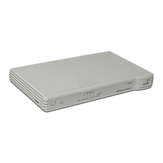
1: I HAPTER NTRODUCING THE Minimum System Your Router requires that the computer(s) and components in your and Component network be configured with at least the following: Requirements Front Panel The front panel of the Router contains a series of indicator lights (LEDs) that help describe the state of various networking and connection operations. - Page 15 In each of these cases, wait until the Router has completed the current operation and the alert LED is Off. Flashing slowly - The Router has completed the Reset to Factory Defaults process, and is waiting for you to reset the unit. To do this, remove power, wait 10 seconds and then re-apply power.
-
Page 16: Rear Panel
1: I HAPTER NTRODUCING THE Rear Panel The rear panel Ethernet Cabler/DSL port, and a power adapter socket. Figure 4 Router - Rear Panel 5 Power Adapter Socket Only use the power adapter supplied with this Router. Do not use any other adapter. -
Page 17: Hardware Installation
Introduction This chapter will guide you through a basic installation of the Router, including: Safety Information WARNING: Please read the before you start. VORSICHT: Bitte lesen Sie den Abschnitt sorgfältig durch, bevor Sie das Gerät einschalten. AVERTISSEMENT: Veuillez lire attentivement la section importantes de sécurité”... -
Page 18: Using The Rubber Feet
Water or moisture cannot enter the case of the unit. Air flow around the unit and through the vents in the side of the case is not restricted. 3Com recommends you provide a minimum of 25 mm (1 in.) clearance. - Page 19 3 Ensure that your modem and computer are both switched on. 4 Use the supplied cable to connect the Router’s Ethernet Cable/DSL port to the modem. Check that the Cable/DSL Status LED lights. 5 Connect your computer to one of the 10/100 LAN ports on the Router. Check that the LAN Status LED for the port lights green.
- Page 20 2: H HAPTER ARDWARE NSTALLATION...
-
Page 21: Setting U P Your Computers
The Router has the ability to dynamically allocate network addresses to the computers on your network, using DHCP. However, your computers need to be configured correctly for this to take place. To change the configuration of your computers to allow this, follow the instructions in this chapter. - Page 22 3: S HAPTER ETTING Figure 6 Local Area Properties Screen 6 Ensure that the options Obtain an IP Address automatically, and Obtain DNS server address automatically are both selected as shown in Click OK. Figure 7 Internet Protocol (TCP/IP) Properties Screen 7 Restart your computer.
-
Page 23: Windows Xp
Windows XP If you are using a Windows XP computer, use the following procedure to change your TCP/IP settings: 1 From the Windows Start menu, select Control Panel. 2 Click on Network and Internet Connections. 3 Click on the Network Connections icon. 4 Double click on LAN or High Speed Connection icon. -
Page 24: Disabling Pppoe And Pptp Client Software
3: S HAPTER ETTING Disabling PPPoE If you have PPPoE client software installed on your computer, you will and PPTP Client need to disable it. To do this: Software 1 From the Windows Start menu, select Settings > Control Panel. 2 Double click on Internet Options. -
Page 25: Running The Setup Wizard
Accessing the The Router setup program is Web-based, which means that it is accessed Wizard through your Web browser (Netscape Navigator or Internet Explorer). To use the Setup Wizard: 1 Ensure that you have at least one computer connected to the Router. Refer to 2 Launch your Web browser on the computer. - Page 26 4: R HAPTER UNNING THE ETUP The Login screen displays Figure 10 Router Login Screen 4 Log in by typing the administrator password (the default password is admin) in the System Password field, and clicking Log in. Be sure to bookmark this screen for easy reference if you should want to change the Router settings.
-
Page 27: Password
3 Type in a Login Timeout. This is the amount of time you want the Router to remain inactive before it returns to the login screen. 3Com recommends entering a new password when setting up the Router for the first time. The Router is shipped from the factory with a default password, admin. -
Page 28: Time Zone
4: R HAPTER UNNING THE ETUP Time Zone Figure 12 Time Zone Screen The Router keeps time by connecting to a Simple Network Time Protocol (SNTP) server. This allows the Router to synchronize the system clock to the Internet. The synchonized clock in the Router is used to record the security log. -
Page 29: Connection Type
down lists. It does not cause the system clock to be updated for daylight savings time automatically. 8 Click Next to display the Connection Type screen. Connection Type Figure 13 Connection Type Screen This Connection Type screen allows you to set up the Router for the type of Internet connection you have. - Page 30 4: R HAPTER UNNING THE ETUP Dynamic IP Address Mode Figure 14 Dynamic IP Screen 1 Some ISPs require a host name. If your ISP has this requirement, enter the host name in the Host Name text box . 2 Either: 3 Click Next.
- Page 31 PPPoE Mode Figure 15 PPPoE Interface Screen To setup the Router for use with a PPP over Ethernet (PPPoE) connection, do the following: 1 Enter your PPP over Ethernet user name in the User Name text box. 2 Enter your PPP over Ethernet password in the Password text box and enter it again in the Retype Password text box.
- Page 32 4: R HAPTER UNNING THE ETUP PPTP Mode Figure 16 PPTP Screen To setup the Router for use with a PPTP connection, use the following procedure: 1 Enter your PPTP server address in the PPTP Server Address text box. 2 Enter your PPTP user name in the User ID text box. 3 Enter your PPTP password in the Password text box, and enter it again in the Retype Password text box.
- Page 33 Figure 17 L2TP Screen To setup the Router for use with an L2TP connection, do the following: 1 Enter your L2TP server address in the L2TP Server text box. 2 Enter your L2TP user name in the User ID text box. 3 Enter your L2TP password in the Password text box, and enter it again in the Retype Password text box.
- Page 34 4: R HAPTER UNNING THE ETUP Static IP Mode Figure 18 Static IP Mode Screen 1 Enter the IP Address provided by your ISP in the IP Address assigned by your Service Provider text box. 2 Enter the Subnet Mask provided by your ISP in the Subnet Mask text box. 3 Enter the Gateway Address provided by your ISP in the Service Provider Gateway Address text box.
-
Page 35: Dns
Figure 19 DNS Screen To set up the Domain Name Server (DNS) information for your Router, do the following: 1 Either: Check the Automatic from ISP check box. Or, If your ISP has provided you with a specific DNS address to use type the DNS Address in the text box. -
Page 36: Hostname And Mac Address
4: R HAPTER UNNING THE ETUP Hostname and MAC Figure 20 Hostname and MAC Address Screen Address 1 Some ISPs require a host name. If your ISP has this requirement, enter the host name in the Host Name text box. 2 Either: 3 Click Next to display the LAN Settings screen. -
Page 37: Lan Settings
IP address for each computer. 4 If required, enter a Local Domain Name. 5 If you use 3Com NBX telephones, enter the IP address of the NBX call processor at 3Com NBX Call Processor. 6 Click Next to display the Configuration Summary screen. - Page 38 When you complete the Setup Wizard, a configuration summary displays. Verify the configuration information of the Router and then click Apply to save your settings. 3Com recommends that you print this page for your records. If you have made changes to the LAN Settings, you may need to reconfigure the computer you are using in order to make contact with the Router again.
-
Page 39: Router Configuration
Navigating This chapter describes all the screens available through the Router Through the Router configuration pages. To get to the configuration pages, browse to the Configuration Router by entering the URL in the location bar of your browser. The default URL is http://192.168.1.1 but if you changed the Router Pages LAN IP address during initial configuration, use the new IP address instead. -
Page 40: Lan Settings
192.168.1.2 and end at 192.168.1.254 Specify the IP address Lease Time. The default is half day If required, specify a local Domain Name If you use 3Com NBX telephones, specify an NBX call processor page “DHCP Clients... - Page 41 IP address for each computer 6 If required, specify the Local Domain Name for your network. 7 If you use 3Com NBX telephones, enter the IP address of the NBX call processor at 3Com NBX Call Processor.
-
Page 42: Internet Settings
5: R HAPTER OUTER ONFIGURATION DHCP Clients List The DHCP Clients List provides details on the devices that have received IP addresses from the Router. The list is only created when the Router is set up as a DHCP server. For each device that is connected to the LAN the following information is displayed: From this screen, you can do the following: As you connect more devices, the client list will grow to a maximum... -
Page 43: Connection To Isp
When you install the Router, you will not need to use the PPPoE software on your PC. PPTP (DSL or Cable) PPTP is only used by some European providers. If the installation instructions that accompany your modem ask you to setup a dialup connection using a PPTP VPN tunnel then select this option. - Page 44 5: R HAPTER OUTER ONFIGURATION Dynamic IP Address To configure the dynamic IP address connection for your Router: 1 Select Dynamic IP Address and then click Next. The Dynamic IP Screen displays (see Figure 25 Internet Settings - Dynamic IP Screen 2 Some ISPs require a host name.
- Page 45 PPPoE To configure the PPPoE connection for your Router: 1 Select PPPoE and then click Next. The PPPoE Interface screen displays (see Figure 26). Figure 26 Internet Settings - PPPoE Interface Screen 2 Enter your PPP over Ethernet user name in the User Name text box. 3 Enter your PPP over Ethernet password in the Password text box and enter it again in the Retype Password text box.
- Page 46 5: R HAPTER OUTER ONFIGURATION PPTP To configure the PPTP connection for your Router: 1 Select PPTP and then click Next. The PPTP screen displays (see Figure 27 Internet Settings - PPTP Screen 2 Enter your PPTP server address in the PPTP Server Address text box. 3 Enter your PPTP user name in the User ID text box.
- Page 47 L2TP Check with your ISP to make sure they support L2TP. To configure the L2TP connection for your Router: 1 Select L2TP and then click Next. The L2TP screen displays (see Figure 28 Internet Settings - L2TP Screen 2 Enter your L2TP server address in the L2TP Server text box. 3 Enter your L2TP user name in the User ID text box.
- Page 48 5: R HAPTER OUTER ONFIGURATION Static IP Address To configure a Static IP Address for your Router: 1 Select Static IP Address and then click Next. The Static IP Address screen displays (see Figure 29 Internet Settings - Static IP Screen 2 Enter the IP Address provided by your ISP in the IP Address assigned by your Service Provider text box.
-
Page 49: Dns
To configure the Domain Name Server (DNS) information for your Router, do the following: 1 Select Internet Settings, then from the sub-menu select DNS. The DNS screen displays (see Figure Figure 30 Internet Settings - DNS Screen 1 Either: Check the Automatic from ISP check box. Or, If your ISP has provided you with a specific DNS address to use, or you chose Static IP Address in the Internet Settings screen, type the DNS Address in the text box. -
Page 50: Hostname & Mac
5: R HAPTER OUTER ONFIGURATION Hostname & MAC To configure the Hostname and MAC Address information for your Router, do the following: 1 Select Internet Settings, then from the sub-menu select Hostname & MAC. The Hostname and MAC Address screen displays (see Figure 31 Internet Settings - Hostname and MAC Address Screen 1 Some ISPs require a host name. -
Page 51: Spi
DMZ to open the client up to unrestricted two-way Internet access. “DMZ” page CAUTION: DMZ reduces network security, and 3Com recommends you only use it on a temporary basis. Stateful Packet Inspection (SPI) inspects, and if required blocks packets at the application layer. - Page 52 5: R HAPTER OUTER ONFIGURATION To configure SPI information on your Router: 1 Select Firewall from the main menu, then select SPI from the sub-menu to display the SPI screen Figure 32 SPI Screen - upper section Figure 33 SPI Screen - lower section Intrusion Detection Feature The Intrusion Detection feature limits access for incoming traffic at the WAN ports.
- Page 53 3 If required, check the RIP defect check box. This feature stops unacknowledged packets from accumulating in the input queue. Stateful Packet Inspection 4 The Stateful Packet Inspection section displays a list of traffic types. If you leave the check box for a traffic type blank, this traffic type is blocked. If you check the check box, the Router allows this type of incoming traffic, but only if the connection was initiated from the local LAN.
-
Page 54: Special Applications
5: R HAPTER OUTER ONFIGURATION DoS Detect Criteria 15 In the Total incomplete TCP/UDP sessions HIGH text box, enter the number of unestablished sessions that will cause the software to start deleting half-open sessions. The defaiult is 300. 16 In the Total incomplete TCP/UDP sessions LOW text box, enter the number of unestablished sessions that must be reached before the software stops deleting half-open sessions. - Page 55 To set up one of the listed Special Applications on your Router, do the following: 1 Select Firewall from the main menu, then select Special Applications from the sub-menu. The Special Applications screen displays Figure 34 Special Application Screen 2 Select an application from the Popular Applications drop-down list. 3 Select the row that you want to copy the settings to from the Copy To drop-down list, and click on Copy To.
-
Page 56: Virtual Servers
5: R HAPTER OUTER ONFIGURATION 4 Click Apply to save the setting for this application. Virtual Servers This function will allow you to route external (Internet) calls for services such as a web server (port 80), FTP server (Port 21), or other applications through your Router to your internal network. -
Page 57: Client Ip Filters
Figure 36 Virtual Server - Add/Edit Screen 3 Enter the IP address of the internal machine in the LAN IP Address text box. 4 Select a protocol type (TCP, UDP or both) from the Protocol Type drop-down list. 5 Enter the LAN Port which the traffic will be routed to in the LAN Port text box. - Page 58 5: R HAPTER OUTER ONFIGURATION To configure Access Control, do the following: 1 Select Firewall from the main menu, then select Client IP Filters from the sub-menu, and make sure the Access Control tab is selected. The Access Control screen displays Figure 37 Access Control Screen 2 At the Enable Filtering Function radio buttons, select Enable or Disable to enable or disable all Access Control rules.
- Page 59 To control access to specific Internet services: 1 Click on Add PC, or click Edit in the Configure column to edit an existing entry. The Access Control - Add PC screen displays Figure 38 Access Control - Add PC Screen 2 Enter a description for the filter you are defining in the Client PC Description field.
- Page 60 5: R HAPTER OUTER ONFIGURATION Figure 39 URL Filter Screen To configure URL Filtering, do the following: 1 Enter the URLs or keywords to be allowed or blocked in the URL/Keyword column. 2 Select either Denied or Allowed from the Mode drop-down list to deny or allow access to web site containing these words.
- Page 61 you set up here are available for selection when you configure access control (see “Access Control”on To configure a schedule rule, do the following: 1 Select Firewall from the main menu, then select Client IP Filters from the sub-menu, and select the Schedule Rule tab. The Schedule Rule screen displays (Figure 40).
-
Page 62: Mac Address Filtering
5: R HAPTER OUTER ONFIGURATION Figure 41 Schedule Rule - Add Rule Screen 3 Enter a name and comment for the schedule rule in the Name and Comment text boxes. 4 Specify the schedule rules for the required days and times. Note that all times should be in 24 hour format. -
Page 63: Dmz
To set up MAC Address Filtering, do the following: 1 Select Firewall from the main menu, then select MAC Address Filtering from the sub-menu. The MAC Address Filtering screen displays (Figure 42). Figure 42 MAC Address Filtering 2 To enable this feature, click the Enable radio button. 3 Enter the MAC address of each client on your network that you want to allow network access in the MAC Address text boxes. -
Page 64: Vpn
5: R HAPTER OUTER ONFIGURATION To put a computer in the DMZ, do the following: 1 Select Firewall from the main menu, then select DMZ from the sub-menu. The DMZ screen displays Figure 43 DMZ Screen 2 Select the ENABLE radio button. 3 The first row in the Public IP Address column defaults to the IP address of the WAN interface. - Page 65 connection between two devices, make sure that they support the same encryption method. Enabling IPSec VPN disables pass-through to IPSec and L2TP over IPSec Virtual Servers on the LAN. Pass-through outbound from clients on the LAN to servers on the Internet is unaffected. PPTP (Point-to-Point Tunneling Protocol) —...
- Page 66 5: R HAPTER OUTER ONFIGURATION To configure a VPN connection on your Router: 1 Select VPN from the main menu.The VPN screen displays Figure 44 VPN Screen 2 In the Enable VPN section, select the Yes radio button for the connection methods you want to use.
-
Page 67: Adding An Ipsec Connection
Adding an IPSec To add an IPSec Connection, or to edit an existing IPSec connection: Connection 1 In the VPN screen, click Add, or click Edit to edit an existing connection. 2 At the Tunnel Type drop-down list, select IPSec. The screen shown in Figure 45 Figure 45 VPN Tunnel Configuration - IPSec Screen 3 Enter a descriptive name for the tunnel at the Tunnel Name text box. -
Page 68: Adding An L2Tp Over Ipsec Connection
3DES is not shipped as standard with the Router due to international restrictions on encryption. If your country permits their use, they can be downloaded from the 3Com Web site at http://www.3com.com 13 Click Apply to save the settings. The IKE Keep Alive feature is not available. - Page 69 Figure 46 VPN Tunnel Configuration - L2TP over IPSec Screen 3 Enter a name for the tunnel at the Tunnel Name text box. 4 Enter the user name that the remote VPN client will use to connect in the User name text box. 5 Enter the password that will need to be supplied to connect in the Password text box.
-
Page 70: Adding A Pptp Connection
5: R HAPTER OUTER ONFIGURATION 11 Type a name for the Remote Party ID in the text box next to the drop-down list. This must be unique for each connection rule that you create. 12 Click Apply to save the settings. Adding a PPTP To add a PPTP Connection, or to edit an existing PPTP connection: Connection... -
Page 71: Snmp
8 If you want to enter details of the remote network, check the Remote Network Setting - Enable check box, then enter the Remote Network Address and Remote Subnet Mask. 9 Click Apply to save the settings. SNMP SNMP (Simple Network Management Protocol) allows remote management of your Router by a PC that has an SNMP management agent installed. -
Page 72: System Tools
5: R HAPTER OUTER ONFIGURATION 3 In the Community column, enter the name of the SNMP communication channel. Your SNMP management agent needs to be configured with this name so that it can communicate with your Router. 4 In the Access column, select either: 5 Check the Valid check box to enable the community. -
Page 73: Restart Router
Use this option to reset all of the configuration settings in the Router to Defaults the factory (default) settings. CAUTION: 3Com recommends that you backup your configuration settings before you reset to factory defaults, otherwise configuration information may be lost. Refer to for details. -
Page 74: Backup/Restore Settings
3Com recommends that you backup your current configuration before performing a firmware update or a reset to factory defaults. This option also enables you to restore a previously saved configuration. -
Page 75: Upgrade
3 Click Restore to restore this configuration file. Upgrade From time to time 3Com may release new versions of the Router’s firmware. Firmware updates contain improvements and fixes to problems that may exist with the current version. -
Page 76: Admin Password
Keep your password in a safe place as you will need this password to log in to the Router in the future. 3Com also recommends that you set a password if you plan to use the Remote management feature of this Router. -
Page 77: Time Zone
To change the password: 1 Select System Tools from the main menu, then select Admin Password from the sub-menu. The Admin Password screen displays Figure 53 Admin Password Screen 2 Enter the current password into the Current password text box. 3 Enter the new password into the New Password and Confirm New Password fields. - Page 78 5: R HAPTER OUTER ONFIGURATION To configure time zone settings: 1 Select System Tools from the main menu, then select Time Zone from the sub-menu. The Time Zone screen displays Figure 54 Time Zone Screen 2 Select the Base Date and Base Time. The Router will use these settings if it is unable to connect to the Internet or SNTP Server.
-
Page 79: Advanced
Advanced From the Advanced Screen, you can configure: The sub-menu topics in the Advanced menu also enable you to configure Routing options, and to configure Dynamic DNS. NAT (Network Address Translation) and IPSec NAT-T (NAT Traversal) Pass-through Universal Plug and Play WAN Ping Blocking Remote Administration NAT —... -
Page 80: Universal Plug And Play
Figure 55 Advanced 2 To disable NAT, select the OFF radio button. 3Com recommends that you leave NAT enabled for maximum security. 3 To enable IPSec NAT-T Pass-through, select the On radio button. 4 If required, continue configuring advanced options on this screen, or click Apply to save the settings. -
Page 81: Wan Ping Blocking
want to use any applications that are Universal Plug and Play compliant, you can enable this feature. To enable Universal Plug and Play: 1 Select Advanced from the main menu. The Advanced screen displays (Figure 2 To enable Universal Plug and Play, select the ON radio button. 3 If required, continue configuring advanced options on this screen, or click Apply to save the settings. -
Page 82: Routing
5: R HAPTER OUTER ONFIGURATION 3 Enter the number of the port that will be used to remotely manage the Router in the Port for remotely manage the router text box. This must be entered in the browser as part of the URL when the remote user logs in. 4 Click Apply to save the settings. - Page 83 Subnet Mask - the subnet mask of the route. If network address and subnet mask are both set to 0.0.0.0, this is the default route. Gateway - the gateway used to route data to the network specified by the network address. To configure a static route: 1 Click on Add to add a new route, or click Edit in the Configure column to edit an existing entry.
- Page 84 4 Select either 1 (for RIPv1) or 2 (for RIPv2) from the Version drop-down list. 3Com recommends that you use RIPv1 if there is any RIP enabled device on your network that does not support RIPv2. In all other case, select RIPv2.
- Page 85 Advanced 8 Click Apply to save the settings. Routing Table Select the Routing Table tab from the Advanced > Routing sub-menu to display routing information used by the Router. The information is displayed in the format shown in Figure 59 Figure 59 Routing Table screen...
-
Page 86: Ddns
5: R HAPTER OUTER ONFIGURATION DDNS Dynamic Domain Name Server (DDNS) enables you to map a static domain name to a dynamic IP address. The Router supports two DDNS providers, TZO.com and DYNDNS. Before you can set up DDNS, you must obtain an account, password and static domain name from your DDNS provider. -
Page 87: Status And Logs
DynDNS If you select DYNDNS: 1 In the Domain Name text box, enter the domain name. 2 In the Account text box, enter the account name. 3 In the Password text box, enter the account password. 4 Click Apply to make this service active. Status and Logs Selecting Status and Logs from the main menu displays the Status Screen, and also displays two sub-menus: Traffic Metering and Logs. -
Page 88: Traffic Metering
5: R HAPTER OUTER ONFIGURATION Traffic Metering The Traffic Metering screen displays the amount of data transmitted to and received from the Internet. This information is provided for guidance only, and may differ from that used by your ISP for billing purposes. To view the Traffic Metering screen: 1 Select Status and Logs from the main menu, then select the Traffic Metering sub-menu. -
Page 89: Support/Feedback
To display log information: 1 Select Status and Logs from the main menu, then select Logs from the sub-menu. The Logs screen displays Figure 63 Logs Screen 2 Either: Support/Feedback Selecting Support/Feedback from the main menu displays the Support screen and the Feedback sub-menu topic. Support Selecting the Support option on the main menu displays the support links screen, which contains a list of Internet links that provide information and... -
Page 90: Feedback
Figure 64 Support Screen Feedback Selecting the Feedback option on the sub-menu displays the Feedback screen and allows you to provide feedback to 3Com on the operation of your Router (Figure 65). This screen should not be used to obtain technical support. -
Page 91: Troubleshooting
Basic Connection Checks Browsing to the If you have connected your Router and computers together but cannot Router browse to the Router configuration screens, check the following: Configuration Screens ROUBLESHOOTING Check that the Router is connected to your computers and to the telephone line, and that all the equipment is powered on. -
Page 92: Connecting To The Internet
6: T HAPTER ROUBLESHOOTING Connecting to the If you can browse to the Router configuration screens but cannot access Internet sites on the Internet, check the following: Connections tab and click on the LAN Settings button at the bottom. Make sure that the Proxy Server option is unchecked. If you cannot browse to the Router, use the winipcfg utility in Windows 95/98/ME to verify that your computer has received the correct address information from the Router. -
Page 93: Forgotten Password And Reset To Factory Defaults
Forgotten Password If you can browse to the Router configuration screen but cannot log in and Reset to because you do not know or have forgotten the password, follow the Factory Defaults steps below to reset the Router to it’s factory default configuration. CAUTION: All your configuration changes will be lost, and you will need to run the configuration wizard again before you can re-establish your Router connection to the Internet. -
Page 94: Power Led Or Power Adapter Ok Led Not Lit
OfficeConnect power adapter you are using. Alternatively, quote the part number for your region: the Router software on the accompanying CD-ROM or 3Com web site ) and upload it to the Router to see if this http://www.3com.com clears the fault (refer to “Recovering from Corrupted Software”... -
Page 95: Recovering From Corrupted Software
Before you start, ensure that one of your computers has a copy of the new software image file stored on its hard disk or available on CD-ROM. The latest software is available on 3Com’s Web site at: www.3com.com 1 Remove power from the Router and disconnect all your computers, except for the one computer with the software image. -
Page 96: Frequently Asked Questions
Internet. Refer to Where can I download software updates for the Router? Updates to the Router software are posted on the 3Com support web site, accessible by visiting: http://www.3com.com If you can log in, refer to “Reset to Factory Defaults”... - Page 97 Frequently Asked Questions After you have downloaded the software from the 3Com Web site, you can upgrade your Router as described in “Upgrade” page...
- Page 98 6: T HAPTER ROUBLESHOOTING...
-
Page 99: Ip Addressing
IP A The Internet The Internet protocol suite consists of a well-defined set of Protocol Suite communications protocols and several standard application protocols. Transmission Control Protocol/Internet Protocol (TCP/IP) is probably the most widely known and is a combination of two of the protocols (IP and TCP) working together. - Page 100 A: IP A PPENDIX DDRESSING For your network to work correctly, all devices on the network must have: The only value that will be different is the specific host device number. This value must always be unique. An example IP address is ‘192.168.100.8’. However, the size of the network determines the structure of this IP Address.
-
Page 101: How Does A Device Obtain An Ip Address And Subnet Mask
This type of IP Address operates on a subnet mask of ‘255.255.0.0’. represented) and a Router might be configured. Table 5 IP Addressing and Subnet Masking Device PC 1 PC 2 PC 3 PC 4 Router How does a Device There are three different ways to obtain an IP address and the subnet Obtain an IP mask. - Page 102 A: IP A PPENDIX DDRESSING an IP address at random from the industry standard subnet of 169.254.x.x (with a subnet mask of 255.255.0.0). If two devices allocate themselves the same address, the conflict is detected and one of the devices allocates itself a new address. Automatic IP addressing support was introduced by Microsoft in the Windows 98 operating system and is also supported in Windows 2000.
- Page 103 ISP I Information Regarding Popular ISPs NFORMATION WAN Types Characteristics Dynamic IP Cable modem ISP, non-hostname based. Need to clone the MAC (Clone MAC) address in the Advanced tab of the Internet Settings page. Dynamic IP Cable ISP, Requires Hostname to authenticate ie.
- Page 104 B: ISP I PPENDIX NFORMATION Static (DSL) Static (Cable) *Bell includes Bell Advantage, Bell Canada, Bell South, PacBell and Southwestern Bell. DSL Modem, always on. Need to enter ALL IP information from ISP in the Static IP address section of the Internet Settings page.
-
Page 105: Technical Specifications
This section lists the technical specifications for the OfficeConnect Cable/DSL Router. OfficeConnect Interfaces Cable/DSL Router Cable/DSL modem connection — 10 Mbps/100 Mbps dual speed Ethernet port (10BASE-T/100BASE-TX) LAN connection — four 10Mbps/100Mbps dual speed Ethernet ports (10BASE-T/100BASE-TX) Operating Temperature 0 °C to 40 °C (32 °F to 105 °F) Power 7VA, 23.9 BThU/hr Humidity... - Page 106 C: T PPENDIX ECHNICAL Safety: EMC: Environmental: EN 60068 (IEC 68) *See System Requirements Operating Systems The Router will support the following Operating Systems: Ethernet Performance The Router complies to the IEEE 802.3i, u and x specifications. Cable Specifications The Router supports the following cable types and maximum lengths: PECIFICATIONS UL60950 EN 60950...
-
Page 107: Safety Information
Important Safety Information WARNING: Warnings contain directions that you must follow for your personal safety. Follow all directions carefully. You must read the following safety information carefully before you install or remove the unit: WARNING: Exceptional care must be taken during installation and removal of the unit. -
Page 108: Wichtige Sicherheitshinweise
D: S PPENDIX AFETY NFORMATION Wichtige Sicherheitshinweise VORSICHT: Warnhinweise enthalten Anweisungen, die Sie zu Ihrer eigenen Sicherheit befolgen müssen. Alle Anweisungen sind sorgfältig zu befolgen. Sie müssen die folgenden Sicherheitsinformationen sorgfältig durchlesen, bevor Sie das Geräts installieren oder ausbauen: VORSICHT: Bei der Installation und beim Ausbau des Geräts ist mit höchster Vorsicht vorzugehen. -
Page 109: Consignes Importantes De Sécurité
Consignes importantes de sécurité AVERTISSEMENT: Les avertissements présentent des consignes que vous devez respecter pour garantir votre sécurité personnelle. Vous devez respecter attentivement toutes les consignes. Nous vous demandons de lire attentivement les consignes suivantes de sécurité avant d’installer ou de retirer l’appareil: AVERTISSEMENT: Faites très attention lors de l'installation et de la dépose du groupe. -
Page 110: Información De Seguridad Importante
D: S PPENDIX AFETY NFORMATION Información de seguridad importante ADVERTENCIA: Las advertencias contienen indicaciones que debe respetar por su seguridad personal. Siga las indicaciones con cuidado. Antes de instalar o retirar la unidad, debe leer detenidamente la siguiente información de seguridad. ADVERTENCIA: Debe tener especial cuidado durante la instalación y retirada de la unidad. -
Page 111: Upport For Your
3Com Extended Warranty and Professional Services is available at http://www.3com.com/ Contact your authorized 3Com reseller or 3Com for additional product and support information. Troubleshoot You will find support tools posted on the 3Com web site at Online http://www.3com.com/ BTAINING UPPORT FOR YOUR RODUCT http://eSupport.3com.com/... -
Page 112: Access Software Downloads
When you contact 3Com for assistance, please have the following information ready: To send a product directly to 3Com for repair, you must first obtain a return authorization number (RMA). Products sent to 3Com, without authorization numbers clearly marked on the outside of the package, will RODUCT http://www.3com.com/prodforms/software/connection_assistan... - Page 113 Pakistan +61 2 9937 5083 You can also obtain support in this region using the following e-mail: apr_technical_support@3com.com Or request a repair authorization number (RMA) by fax using this number: Europe, Middle East, and Africa Telephone Technical Support and Repair...
- Page 114 BTAINING UPPORT FOR YOUR Country Telephone Number Latin America Telephone Technical Support and Repair Antigua 1 800 988 2112 Argentina 0 810 444 3COM Aruba 1 800 998 2112 Bahamas 1 800 998 2112 Barbados 1 800 998 2112 Belize...
-
Page 115: Nd Ser Software Icense Greement
Subject to the restrictions set forth herein, the Software is licensed to be used on any workstation or any network server owned by or leased to you, for your internal use, provided that the Software is used only in connection with this 3Com product. You may reproduce and provide one (1) copy of the Software and Documentation for each such workstation or network server on which the Software is used as permitted hereunder. - Page 116 The Software is delivered as ìCommercial Computer Softwareî as defined in DFARS 252.227-7014 (June 1995) or as a commercial item as defined in FAR 2.101(a) and as such is provided with only such rights as are provided in this Agreement, which is 3Com’s standard commercial license for the Software.
-
Page 117: Auto-Negotiation
LOSSARY 10BASE-T The IEEE specification for 10 Mbps Ethernet over Category 3, 4 or 5 twisted pair cable. 100BASE-TX The IEEE specification for 100 Mbps Fast Ethernet over Category 5 twisted-pair cable. Access Point An Access Point is a device through which wireless clients connect to other wireless clients and which acts as a bridge between wireless clients and a wired network, such as Ethernet. - Page 118 DNS Server Address DNS stands for Domain Name System, which allows Internet host computers to have a domain name (such as 3com.com) and one or more IP addresses (such as 192.34.45.8). A DNS server keeps a database of host computers and their respective domain names and IP addresses, so that when a domain name is requested (as in typing “3com.com”...
-
Page 119: Infrastructure Mode
Ethernet A LAN specification developed jointly by Xerox, Intel and Digital Equipment Corporation. Ethernet networks use CSMA/CD to transmit packets at a rate of 10 Mbps over a variety of cables. Ethernet Address See MAC address. Fast Ethernet An Ethernet system that is designed to operate at 100 Mbps. Firewall Electronic protection that prevents anyone outside of your network from seeing your files or damaging your computers. - Page 120 LOSSARY consists of 32 bits divided into two or three fields: a network number and a host number or a network number, a subnet number, and a host number. IP Address Internet Protocol Address. A unique identifier for a device attached to a network using TCP/IP.
-
Page 121: Network Interface
LOSSARY Network Interface A circuit board installed into a piece of computing equipment, for Card (NIC) example, a computer, that enables you to connect it to the network. A NIC is also known as an adapter or adapter card. Protocol A set of rules for communication between devices on a network. - Page 122 LOSSARY Subnet mask A subnet mask, which may be a part of the TCP/IP information provided by your ISP, is a set of four numbers configured like an IP address. It is used to create IP address numbers used only within a particular network (as opposed to valid IP address numbers recognized by the Internet, which must assigned by InterNIC).
- Page 123 LOSSARY Wide Area Network. A network that connects computers located in geographically separate areas (for example, different buildings, cities, or countries). The Internet is an example of a wide area network. Wired Equivalent Privacy. A shared key encryption mechanism for wireless networking.
- Page 124 LOSSARY...
- Page 125 NDEX access control 57 Addresses IP 99 admin password resetting 76 administration remote 81 Advanced RIP 83 routing table 85 Automatic Addressing 101 backup settings 74 Cable Specifications 106 client IP filters 57 access control 57 schedule rule 60 URL filter 59 Connection Policy 53 Conventions notice icons, About This Guide 8...
- Page 126 NDEX ping blocking 81 plug and play 80 PPPoE 24, 31, 42 PPTP 43 remote administration 81 Reset to Factory Defaults 93 reset to factory defaults 73 restart router 73 restore settings 74 RIP 83 routing 82 RIP 83 routing table 85 static route 82 routing table 85 Safety Information 17...
- Page 127 ECLARATION OF We declare under our sole responsibility that the ONFORMITY Model: 3CR858-91 to which this declaration relates, is in conformity with the following standards or other normative documents: CSA S TATEMENT This Class B digital apparatus meets all requirements of the Canadian Interference-Causing Equipment Regulations.
- Page 130 3Com Corporation, Corporate Headquarters, 350 Campus Drive, Marlborough, MA USA 01752-3064 To learn more about 3Com products and services, visit our World Wide Web site at www.3com.com All specifications are subject to change without notice. Copyright © 2004 3Com Corporation. All rights reserved.
Need help?
Do you have a question about the OfficeConnect 3CR858-91 and is the answer not in the manual?
Questions and answers