Tektronix TTR500 series Manual
Vector network analyzer
Hide thumbs
Also See for TTR500 series:
- Programmer's manual (321 pages) ,
- Technical reference manual (51 pages) ,
- Quick start manual (14 pages)
Table of Contents
Advertisement
Quick Links
Download this manual
See also:
Instruction Manual
Advertisement
Table of Contents

Subscribe to Our Youtube Channel
Related Manuals for Tektronix TTR500 series


Summary of Contents for Tektronix TTR500 series
- Page 1 TTR500 Series Vector Network Analyzer Printable Help *P077125400* 077-1254-00...
- Page 3 TTR500 Series Vector Network Analyzer Printable Help www.tek.com 077-1254-00...
- Page 4 Copyright © Tektronix. All rights reserved. Licensed software products are owned by Tektronix or its subsidiaries or suppliers, and are protected by national copyright laws and international treaty provisions. Tektronix products are covered by U.S. and foreign patents, issued and pending. Information in this publication supersedes that in all previously published material.
-
Page 5: Table Of Contents
Table of Contents Table of Contents Introduction Introduction to TTR500 series VNAs ................Product documentation TTR500 series product documentation................Get started with the VNA Understand the VNA ....................The front panel...................... The rear panel ....................... System requirements ....................Power source specifications .................. - Page 6 Distinction from factory error correction function ............Apply port extensions ..................... Loss calculation ....................Partial overwrite ....................Additional calibration options Manage calibration kits ................... Add/Modify a calibration kit ..................Define a calibration standard ................Specify a subclass..................... TTR500 Series User Manual...
- Page 7 Relative value display (Delta mode)................Couple/Decouple markers ..................Marker search operations ..................Set search range ....................Maximum and minimum values ................Search tracking....................Target search ....................... Peak search ......................Bandwidth search....................Notch search for bandwidth ..................TTR500 Series User Manual...
- Page 8 More options ....................... Connections ......................Use Connection Manager ..................Simulator ......................Load SnP....................... Noise Floor ....................Log severity and OPC logger ..................Default settings Stimulus options ....................Channel/Trace options .................... Response options ....................Markers/Analysis options..................System options ..................... TTR500 Series User Manual...
- Page 9 Measurement accessories ..................Attenuators and bias tee ..................Cables ......................Adapters and test cables..................Accessory cables.................... Calibration kits ....................Standard Functions Standard Functions ....................Maintain your VNA Maintain your VNA ..................... Clean the VNA....................Return the VNA ....................TTR500 Series User Manual...
- Page 10 Table of Contents Troubleshoot your VNA Troubleshoot the VNA ..................IEEE error messages .................... VNA error messages .................... Warnings and notifications ..................Index TTR500 Series User Manual...
-
Page 11: Introduction To Ttr500 Series Vnas
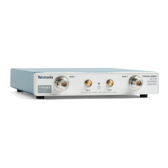
Introduction to TTR500 series VNAs Introduction to TTR500 series VNAs The TTR500 series (503A/506A) Vector Network Analyzer (VNA) is a portable, 2–port network analyzer. The VNA operates over a frequency range of 100 kHz-3 GHz (TTR503A) and 100 kHz-6 GHz (TTR506A). - Page 12 Introduction Introduction to TTR500 series VNAs TTR500 Series User Manual...
-
Page 13: Product Documentation
Product documentation TTR500 series product documentation TTR500 series product documentation In addition to the compiled help file, these manuals are available in the TTR500 series product documentation set: Quick Start Guide containing installation, safety, and compliance instructions Programmer’s reference Specifications and performance verification Security and declassification... - Page 14 Product documentation TTR500 series product documentation TTR500 Series User Manual...
-
Page 15: Get Started With The Vna
first connect the VNA to a Windows PC, VectorVu-PC installs on the machine. Use VectorVu-PC to process measurement data captured using the TTR500 series VNAs or view data obtained using other VNAs. These topics describe the hardware and software interfaces of the TTR500 series VNA. - Page 16 SMA 50 Ω female port 10 dBm, 0 VDC (reserved for future use) RF Port 2 N-type 50 Ω female test port for device-under-test (DUT) connection. Use either RF port for stimulus source or response receiver. Maximum operational RF input level 10 dBm (100 kHz—6 GHz) TTR500 Series User Manual...
-
Page 17: The Rear Panel
Bias 1 Provides bias input for RF port 1 System requirements Each TTR500 series VNA instrument connects to a Windows PC machine and requires 1 USB port. The VectorVu-PC software operates on Windows 7/8/10 operating systems. Power source specifications Characteristic... -
Page 18: Install Vectorvu-Pc
NOTE. If you need to perform power calibration to measure active devices, install Tektronix Power Meter Apps V4_5 to use the Tektronix PSM Series Power Meters. For other supported power meters and power sensors, see Power calibration requirements. -
Page 19: Vectorvu-Pc Vector Analysis Software
Use VectorVu-PC to make network parameter measurements of passive components and active devices. You can also use VectorVu-PC to view measurement data recorded in touchstone files (S1P, S2P formats) using other VNAs as well as data generated from circuit simulation software. TTR500 Series User Manual... -
Page 20: Screen Area
The menu bar has several groups of options available as pull-down menus. Each of the option groups has a corresponding set of soft keys in the soft key panel. You can access all of these menus using a mouse or touch screen. TTR500 Series User Manual... - Page 21 Menu bar In the Response option group: Action Soft key Show/hide the menu bar Display > Menu Bar > Display Menu Bar Display > Menu Bar > Bar Font Set the font size for the menu bar TTR500 Series User Manual...
-
Page 22: Data Entry Bar
Set frequency range, sweep, power, and trigger parameters. Response Measure system response for the stimulus through network parameters, calibrate the DUT, and set display options. System Select language options, manage device connections, save and recall states, or restore factory preset. TTR500 Series User Manual... -
Page 23: Instrument Status Bar
The Sweep Setup submenu becomes the active menu. See Also Instrument status bar Instrument status bar The instrument status bar displays settings and usage information about your TTR500 VNA. Use the corresponding soft key paths to change these settings. TTR500 Series User Manual... - Page 24 In Progress progress. Trigger source Trigger source used: Internal Stimulus > Trigger > More > Trigger Internal Source External Manual SCPI Reference clock source Clock source used: Internal System > More > Reference Clock Internal Source External TTR500 Series User Manual...
-
Page 25: Channel Status Bar
All other settings apply only when VectorVu-PC has an active connection with a TTR500 VNA. See Also Channel status bar Channel status bar The channel status bar displays these parameters about the channel. TTR500 Series User Manual... -
Page 26: Graph Area
You can display channels or traces individually by selecting: Channel / Trace > Channel > Channel Layout Channel / Trace > Trace > Trace Layout TTR500 Series User Manual... -
Page 27: Display Update
When you need to print an image of the graph area, invert the colors of the graph to reduce ink usage and improve clarity on paper. Select this option in Response > Display > Invert Color. TTR500 Series User Manual... - Page 28 Get started with the VNA Graph area TTR500 Series User Manual...
-
Page 29: Set Up The Vna
Set graph layout to display Channel / Trace > Channel > Channel Layout assigned channels Maximize active channel Channel / Trace > Channel > Max Set the active channel Channel / Trace > Channel > Active TTR500 Series User Manual... -
Page 30: Set Traces
When you use the Previous and Next soft keys, you can switch between channels to see the traces they contain. To view the graphs of multiple or all channels simultaneously, change the display configuration: TTR500 Series User Manual... -
Page 31: Multiple Traces
Trace > Trace Layout. Characteristic impedance (system Z The characteristic impedance of a TTR500 series VNA is fixed at 50 Ω. Set stimulus conditions Use settings in the Stimulus option group to define these stimulus parameters to provide to the DUT. -
Page 32: Power Menu
Value RF Out Yes – Enable stimulus signal Sweep Setup > Power Menu > RF Out output. In case of power trip, use this setting to turn output back ON. No – Cannot perform measurements. TTR500 Series User Manual... -
Page 33: Avoid Spurious Function
, the forward traveling wave enters the network as a at port 1 and exits as b at port 2. The reverse wave enters the network as a at port 2 and exits as b at port 1. TTR500 Series User Manual... -
Page 34: Set S-Parameters
Test signal at port 2 when stimulus is on port 1 Test signal at port 1 when stimulus is on port 2 Test signal at port 2 when stimulus is on port 2 Reference signal at port 1 when stimulus is on port 1 TTR500 Series User Manual... -
Page 35: Set The Bias Tee
1. Connect a power supply to the bias tee connectors in the rear panel for each port. 2. In System > More > Bias Tee, enable the bias tee function. NOTE. Do not power the bias tee connectors during calibration to avoid damage to calibration standards. TTR500 Series User Manual... -
Page 36: Select A Data Format
When you represent complex numbers in the polar format, the magnitude of the number is the displacement from a reference point while the phase becomes the counter-clockwise angular displacement from a reference direction. You indicate the frequency using markers since the polar format does not have a frequency axis. TTR500 Series User Manual... -
Page 37: Smith Chart Format
Real and imaginary parts Smith chart format The Smith chart maps reflection coefficients of measurement data from the DUT to normalized impedances. You plot traces using the same information as in the polar format. Frequencies are indicated by markers. TTR500 Series User Manual... -
Page 38: Set The Scale
The scale sets the axis of the display plot in order to zoom in to points of interest or view all trace measurements for a channel simultaneously. To set the scale, 1. Set a reference position on the graph (Response > Scale > Reference Position). 2. Set the scale for your display: Auto scale Manual scale TTR500 Series User Manual... -
Page 39: Auto Scale
Sets the value of the reference line with respect to the Y-axis. Applies only to the active trace. Polar and Smith chart formats In polar and smith charts, you adjust the scale by a displacement to the outermost circle. Specify this using the Scale/Div value in Response > Scale. TTR500 Series User Manual... -
Page 40: Set A Reference Line Value
Response > Display > Labels > Display Title Label channel Invert the display color Response > Display > Invert Color > Inverted sets the display against a white background Response > Display > Invert Color > Normal sets the display against a black background TTR500 Series User Manual... -
Page 41: What Is Calibration
Systematic errors occur due to manufacturing imperfections in components of the measurement system. Since these errors occur every time you perform a measurement, a calibration operation can help remove systematic errors from VNA measurements. TTR500 Series User Manual... -
Page 42: Calibration Workflow
Based on these measurements, the VNA determines the systematic error correction. 4. Apply the systematic error correction to measurements made on the DUT. NOTE. You perform calibration on a single channel at a time since the operation relies on the stimulus provided to the channel. TTR500 Series User Manual... -
Page 43: The Calibration Plane
When the adapter is outside the calibration plane, you can remove the systematic error effects of the adapter from your measurements by using the S-parameters of the adapter (if they are known or can be measured). TTR500 Series User Manual... -
Page 44: Definitions
Cal > Cal Kit and choose from the list of preloaded kits. If you want to select a different calibration kit, you modify an empty kit according to the standards required. See Also: Add/Modify a Calibration Kit TTR500 Series User Manual... -
Page 45: Select A Calibration Method
Calibration Select a calibration method Select a calibration method You can perform these calibrations using the TTR500 series VNA. Select these methods in Response > Cal. Measure- Available Errors ment Pa- Calibration Type Standards Soft key Corrected rameters Accuracy Response calibration Short Calibrate >... - Page 46 Calibrate > Reflection High 1–port SOL tracking Open Directivity Load Source match 2–port SOLT Full 2–port Short Calibrate > Reflection High 2–port SOLT tracking Open Transmis- Load sion track- Thru Directivity Source match Load match Isolation TTR500 Series User Manual...
-
Page 47: Calibrate The Vna
IF Bandwidth. Response calibration (Short/Open) - Reflection Test 1–port calibration Connect an Open or Short standard to a test port of the VNA to perform reflection test. Calibration eliminates the reflection tracking error from the network. TTR500 Series User Manual... -
Page 48: Response Calibration (Thru) - Transmission Test
Partial overwrite. Response calibration (Thru) - Transmission Test 2–port calibration Connect a Thru standard between the test ports of the VNA to perform transmission test. Calibration eliminates the frequency response transmission tracking error from the network. TTR500 Series User Manual... - Page 49 When the calibration measurement is complete, a check mark appears next to the Thru button in the port dialog box. 5. For an optional isolation calibration, connect the Load standard to each of the test ports. Click Isolation in the dialog box to make the calibration measurement. TTR500 Series User Manual...
-
Page 50: 2-Port 1-Path Solt (Enhanced Response) Calibration
Connect Open, Short, or Load standards to stimulus port or connect Thru standard between stimulus and response ports. For isolation calibration, use Load on ports 1 and 2. Calibration eliminates directivity error, reflection tracking, source match error, transmission tracking error and crosstalk (isolation measurement) from the network. TTR500 Series User Manual... - Page 51 When the measurement is complete, a check mark appears next to the Open standard button in the port dialog box. 5. Repeat steps 3 and 4 for the Short, Load, and Thru standards. For the Thru standard measurement, connect the standard between the stimulus and response ports. TTR500 Series User Manual...
-
Page 52: 1-Port Sol Calibration (Reflection Test)
2. Select the test port where you perform the 1–port SOL calibration. The dialog box for the test port opens. 3. Connect the Open standard from the calibration kit to the test port of the VNA. TTR500 Series User Manual... -
Page 53: 2-Port 2-Path Solt (Full Two Port) Calibration
Connect Thru standard between the two VNA ports. Measure both transmission and reflection in both directions. Measure S parameters Calibration eliminates frequency response reflectivity tracking error, directivity, source match error, load match error, transmission tracking and crosstalk (isolation measurement). TTR500 Series User Manual... -
Page 54: Apply Error Correction
You apply the error correction to a channel (and consequently to all the traces it contains). Enable error correction To enable/disable the error correction function, in Response > Cal, click the Correction soft key. You can see the status of the error correction function: TTR500 Series User Manual... -
Page 55: Distinction From Factory Error Correction Function
To account for the delay of the test fixture, you can move the calibration reference plane. The new calibration plane then exists at the terminals of the DUT. You do this by applying port extensions. TTR500 Series User Manual... - Page 56 Loss 2, specify the loss (in dB) and frequency for the higher frequency limit. Use the check boxes to enable/disable the loss values and compare how that affects your measurement. 6. Specify the Velocity Factor for the medium of extension. Typical values are: TTR500 Series User Manual...
-
Page 57: Loss Calculation
When Loss2 is specified: The total loss at frequency f is given by where: When Loss2 is not specified: The total loss at frequency f is given by TTR500 Series User Manual... -
Page 58: Partial Overwrite
You can only update calibration coefficients that have already been calculated. For example, if you perform a 1-port calibration, you cannot use the overwrite feature for the other port to convert the 1–port procedure into a 2–port calibration. TTR500 Series User Manual... -
Page 59: Manage Calibration Kits
2. Once you have selected a calibration kit, modify it by clicking Cal > Modify Cal Kit. 3. Define a calibration standard. Select Cal > Modify Cal Kit > Define Standards. Select a standard and enter values for settings in the dialog box. TTR500 Series User Manual... -
Page 60: Specify A Subclass
1. Select Response > Cal > Modify Cal Kit > Specify Subclass. 2. Select a subclass to modify. You can set an existing subclass (Male-Male DUT) or pick an empty subclass. The subclass dialog box opens. TTR500 Series User Manual... -
Page 61: Additional Calibration Kit Operations
fixed by the power meter. The accuracy and range of measurement can be limited by the power meter as well as by the power supplied. Set the channel frequency range according to the supported frequency range of the power meter. TTR500 Series User Manual... -
Page 62: Power Calibration Workflow
U2000 series U2020 series Loss compensation table Prepare a loss compensation table in comma-separated value (CSV) format to account for the fixture losses at every frequency. The first column indicates frequency (Hz) and the second column indicates TTR500 Series User Manual... -
Page 63: Procedure
VNA stores this reading. 8. If you want to compensate for losses in fixtures and cables, check Enable Loss Compensation. Select a CSV file that contains the loss compensation data. TTR500 Series User Manual... -
Page 64: Receiver Calibration
3. Select Calibration. The Receiver Calibration dialog box opens. 4. Select the receiver and source ports. 5. Click Calibrate. Once the calibration is complete, the error correction is enabled on the receiver port. You can disable it in Receiver Calibration > Error Correction. TTR500 Series User Manual... -
Page 65: Unknown Thru Calibration
The unknown thru loss impacts the accuracy of the calibration, and hence the measurement accuracy. The unknown thru must be reciprocal (S NOTE. The accuracy of a Thru standard with specific delay and loss characteristics is always higher than the accuracy of an Unknown Thru standard. TTR500 Series User Manual... - Page 66 Additional calibration options Unknown thru calibration TTR500 Series User Manual...
-
Page 67: Set Trigger For Measurement
The trigger sweep order applies to all trigger modes. Set a trigger source You use the trigger source to generate a trigger signal that initiates the measurement. Select a trigger source in Stimulus > Trigger > More > Trigger Source. TTR500 Series User Manual... -
Page 68: Set A Trigger Mode
This is the default mode. VNA is always in armed state (never in hold state). Trigger signal causes VNA to perform a sweep and return to armed state. Repeat sweep every time trigger source detects a trigger signal. TTR500 Series User Manual... -
Page 69: Set The Trigger Scope
0–1 second. Upon receipt of a trigger signal, the triggering action is delayed by this time. Use the external trigger delay function to handle electrical or mechanical delays in external equipment involved in the test setup. TTR500 Series User Manual... -
Page 70: Averaging
Click Response > Avg > Avg Trigger to enable the feature. NOTE. You must have the averaging function enabled to use the averaging trigger. TTR500 Series User Manual... -
Page 71: Sweep Time Calculation
: Time required to set up each point in a sweep /IFBW : Time required to make a measurement at a frequency point. This value is inversely proportional to the IFBW. : Total time required to complete a measurement at nth frequency point TTR500 Series User Manual... -
Page 72: Trigger Sweep
Any delay provided to the trigger signal (through Stimulus > Trigger > More > Ext Trig Delay) applies between the detection of the trigger signal and the sweep delay. See Also Set trigger for measurement Additional trigger options Averaging TTR500 Series User Manual... -
Page 73: Use Markers On A Trace
You can also set a reference marker in Setup > More by selecting the Ref Marker option. See Also Set up marker display Reference markers Set up marker display These topics cover several display settings you can select for markers: Select a display mode Relative value display (Delta mode) Couple/Decouple markers TTR500 Series User Manual... -
Page 74: Marker Display Format
Smith chart – Real/Imag Real component Imaginary component Smith chart – R+jX Resistance Reactance Smith chart – G+jX Conductance Susceptance Polar – Lin/Phase Linear amplitude Phase Log amplitude Phase Polar – Log/Phase Polar – Real/Imag Real component Imaginary component TTR500 Series User Manual... -
Page 75: Select A Display Mode
(unless the value falls on a measurement point). In the continuous mode, you place markers on actual measurement points as well as the interpolations that happen between them. Select one of these modes in Markers/Analysis > Function > Discrete. TTR500 Series User Manual... -
Page 76: Relative Value Display (Delta Mode)
You cannot couple markers across different channels. Marker couplings are independent from each other. Marker search operations Use options in Markers/Analysis > Search to perform these search operations: TTR500 Series User Manual... -
Page 77: Set Search Range
With search tracking enabled, the VNA executes the search again on a new sweep measurement and the marker moves to the maximum point on the new sweep. TTR500 Series User Manual... -
Page 78: Target Search
first matching point to the next. NOTE. When you use target search, regardless of continuous or discrete mode, the search returns the nearest measurement point that satisfies the specified conditions of target value and transition type. TTR500 Series User Manual... -
Page 79: Peak Search
You perform the bandwidth search to determine the bandwidth of a trace. The bandwidth search also helps you to identify the following parameters associated with a stopband or passband based on the stimulus value of the active marker: TTR500 Series User Manual... - Page 80 3. Click the Markers/Analysis > Search > Bandwidth toggle button to enable the search. The VNA displays high and low frequencies, the center frequency, bandwidth, insertion loss and Q value in the upper left corner of the channel display. TTR500 Series User Manual...
-
Page 81: Notch Search For Bandwidth
3. Click the Markers/Analysis > Search > Notch toggle button to enable the search. The VNA displays lower and higher cutoff frequencies, the center frequency, bandwidth, insertion loss and Q value in the upper left corner of the trace. TTR500 Series User Manual... -
Page 82: Trace Data Math Operations
Response > Display > Memory > Data Math. These math operations apply to every point on the data trace and its corresponding point on the memory trace. Trace operations are done in the linear magnitude and phase format: TTR500 Series User Manual... -
Page 83: Normalize Data
The Normalize feature automates the tasks of saving a memory trace and performing a Data/Mem operation. Use this feature when you need to perform these operations repetitively. In the Response option group, select Display > Memory > Normalize. TTR500 Series User Manual... -
Page 84: Save Vna State
Save touchstone (SnP) files Recall saved data You can retrieve saved data in the VNA when the information is in one of these formats: State (*.state) State+calibration (*.cstate) State+data (*.dstate) State+calibration+data (*.cdstate) All state files (*.*state) TTR500 Series User Manual... -
Page 85: Limitations When Recalling Data
For example, a 2–port model results in the measurement of 4 S-parameters in a 2x2 matrix: [S ]. The corresponding touchstone file that contains these S-parameters is an S2P file. The TTR500 series VNAs support S1P and S2P formats for 1–port and 2–port models respectively. The S-parameters are recorded as complex numbers that indicate:... -
Page 86: S1P Files
*IDN? query. The data portion of the file contains a list of frequencies along with the matrix of S-parameters for a 2–port device (S , and S ). The S-parameters are in complex format, depending on the port used for measurements. TTR500 Series User Manual... -
Page 87: Expand Dynamic Range
The exponential average is weighted by an averaging factor that you specify. For any point that is a vector quantity, the sweep averaging (A ) for the nth sweep operation at that point is: TTR500 Series User Manual... -
Page 88: Improve Phase Measurement Accuracy
2. Enter the delay value as a length of lossless transmission line (m) or a measure of time (seconds). 3. Specify a velocity factor. Typical values are: Medium Velocity Factor Polyethylene dielectric cable 0.66 PTFE Dielectric TTR500 Series User Manual... -
Page 89: Phase Offset
This option allows you to include a predetermined value to the frequency to account, for example, the addition of a cable. In Scale > Phase Offset, specify a phase offset value between –360 ° to +360 °. See Also Expand dynamic range Improve measurement throughput TTR500 Series User Manual... -
Page 90: Improve Measurement Throughput
Measurement accuracy improves when you enable the error correction by calibrating the VNA. To improve your measurement throughput, switch off the factory correction. In System > More > System Correction, click the System Correction button to toggle the setting off. TTR500 Series User Manual... -
Page 91: System Option Group
Reference Clock Source Beep System Correction Connections Simulator Log Severity OPC Logger Save/Recall Use the options in this set to save channel and trace information to your system. See Also: Save VNA state System option group TTR500 Series User Manual... -
Page 92: Preset
Default settings for System options Language You can configure the user interface of VectorVu-PC dynamically in any of these languages: English Japanese Korean Vietnamese Chinese Taiwanese Mandarin See Also: System option group Default settings for System options TTR500 Series User Manual... -
Page 93: More Options
Connections The Connection Manager window displays the instruments that VectorVu-PC can detect. These are: TTR500 series VNAs connected to your system Internal simulator available in VectorVu-PC. This is a software application that allows you to operate VectorVu-PC without an instrument connection. -
Page 94: Use Connection Manager
Connections Use Connection Manager Use Connection Manager to pair TTR500 series VNAs with one or more instances of VectorVu-PC. When you connect a TTR500 series VNA to your Windows machine, the system recognizes and copies over driver files from the VNA device. Connection Manager uses these files to identify the VNA. -
Page 95: Simulator
VNA. It limits the smallest measurement that can be isolated from the noise. Ideally, a lower noise floor is better for more accurate measurements. See Also System options Connections TTR500 Series User Manual... -
Page 96: Log Severity And Opc Logger
If you notice a problem in the performance of your VNA that indicates a service issue, use the log severity and OPC logger options to create and send log files to Tektronix. These settings allow you to change the type of information that the device logs. Use these options in combination to log the performance of the VNA. -
Page 97: Default Settings
Points sweep Sweep type Sweep Setup > Set type of sweep Linear frequency Channel Sweep Type Avoid spurious Sweep Setup > Avoid spurious Channel Avoid Spurious NOTE. The default setting changes to NO in simulator mode. TTR500 Series User Manual... -
Page 98: Channel/Trace Options
Select number of Trace traces per channel Active window Window > Active Select active window Channel Channel layout Channel > Channel Set channel layout. Channel Layout See Also Stimulus options Response options Markers / Analysis options System options TTR500 Series User Manual... -
Page 99: Response Options
Bar font Display > Menu Bar Select menu bar font Analyzer > Bar Font size Averaging factor Avg > Factor Select number of Channel traces to average Averaging Avg > Averaging Enable/disable NO (disable averaging) Channel averaging TTR500 Series User Manual... - Page 100 Cal > Correction Enable/disable error Channel correction Calibration trigger Cal > More > Cal Select calibration Internal Channel source Trig Source trigger source See Also Stimulus options Channel / Trace options Markers / Analysis options System options TTR500 Series User Manual...
-
Page 101: Markers/Analysis Options
Couple/decouple YES (couple traces) Channel traces for marker action Discrete mode Function > Discrete Discrete Set display mode for Channel marker to discrete mode See Also Stimulus options Channel / Trace options Response options System options TTR500 Series User Manual... -
Page 102: System Options
More > Log Severity Control on logging Warning Analyzer severity OPC logger More > OPC Logger Enable/disable OPC NO disable OPC Analyzer logger logger) See Also Stimulus options Channel / Trace options Response options Markers / Analysis options TTR500 Series User Manual... -
Page 103: Frequency Response Of A Band Pass Filter
2. Connect the female terminal of the filter to port 2 of the VNA using an adapter cable. 3. In VectorVu-PC, set these parameters. The values below apply for the band pass filter used in this example. Select appropriate values based on the characteristics of the filter you use. TTR500 Series User Manual... -
Page 104: Record S-Parameters
4. Repeat steps 2 and 3 for the other S-parameters. The active channel displays all 4 traces. 5. To view the traces in separate windows, in Channel / Trace > Trace > Trace Layout, select a configuration for four traces. TTR500 Series User Manual... -
Page 105: Bandwidth Search
3. To perform the bandwidth search, select Markers / Analysis > Search > Bandwidth. 4. In Markers / Analysis > Search > More > Bandwidth Value, specify 3 dB. The VNA displays these bandwidth parameters in the upper left corner of the graph: Bandwidth Center frequency Lower cutoff frequency TTR500 Series User Manual... -
Page 106: Use Touchstone (Snp) Files For Offline Analysis
SnP file, you can use the file to perform analysis offline and away from the test setup. Also, you do not require the device for analysis as long as the SnP file contains all the S-parameter information. TTR500 Series User Manual... -
Page 107: Save An S2P File
5. Verify the S-parameter information contained in the S2P file. In Response > Measure, select any S-parameter and the graph should populate with the corresponding trace, reading data from the S2P file you recalled. See Also Frequency response of a band pass filter TTR500 Series User Manual... - Page 108 Measurement Examples Use touchstone (SnP) files for offline analysis TTR500 Series User Manual...
-
Page 109: How The Vna Operates
How the VNA operates How the VNA operates The TTR500 series VNAs operate over frequency ranges of 100 kHz – 3 GHz (TTR503A) and 100 kHz – 6 GHz (TTR506A). The VNA measures RF and microwave electronic components by: Providing a stimulus signal that is stepped over a range of measurement frequencies. -
Page 110: Directional Coupler
RF source feed to the directional coupler. The signals become an output from the measurement port. This output signal is used as a stimulus for S-parameter measurements. Receivers There are 6 receivers in the TTR500 series VNA device. Each receiver can measure the magnitude and phase of a signal. Incident receivers (b Each measurement port has a receiver that measures the signal incident to the port. -
Page 111: Usb
Product information Device information The USB 2.0 provides bidirectional communication between the TTR500 series VNA and the host computer. Use a cable to connect the USB port on the VNA to either a USB 2.0 or a USB 3.0 port on a computer. - Page 112 Every TTR500 unit is defined by the model followed by its serial number and a unique identifier. The identifier changes: When you get the unit serviced at Tektronix. Every time the internal USB drive is programmed. The device information display also shows the version of VectorVu-PC that is running on your system.
-
Page 113: Software Download
Number of times the VNA was powered on Results of the power on test Number of switching times of the internal mechanical relay Number of times of overload Event log To delete this log of data, in the programmatic interface, use SCPI.SERVice.LOGGing.CLEar TTR500 Series User Manual... -
Page 114: Recommended Calibration Kits
Product information Recommended calibration kits Recommended calibration kits Tektronix recommends the usage of these standard calibration kits with the TTR500 series VNA devices. Calibration kit Description Matching adapter Description THRU-716-FM CALMECH-716 7/16 OSLT Mechanical Cal 7/16 OSLT Mechanical Cal Kit MF Kit 0 to 7.5 GHz (SPINNER... -
Page 115: Measurement Accessories
Product information Measurement accessories Measurement accessories These accessories are available for use with the TTR500 series VNA instruments. Contact your local Tektronix office or order online at www.tek.com. Specify the part number for the accessory you need. Product Tektronix part number... -
Page 116: Adapters And Test Cables
Coaxial adapter, MIN loss impedance matching PAD, 50 Ω N(M) to 75 Ω BNC(F), 013042200 1.35 VSWR MAX, 5.7+/-0.5dB INS loss, 3 GHz PAD, 50/75 Ω, minimum loss, type-N(M) 50 Ω to type-F(F) 75 Ω 015078700 TTR500 Series User Manual... -
Page 117: Accessory Cables
Calibration kit, 4-in-1 7/16 (m) short, open, load, through, 6 GHz Calibration kit, 4-in-1 type-N (f) short, open, load, through, 75 Ω, 3 GHz CALSOLTNF-75 Calibration kit, 4-in-1 type-N (m) short, open, load, through, 75 Ω, 3 GHz CALSOLTNM-75 TTR500 Series User Manual... - Page 118 Product information Measurement accessories TTR500 Series User Manual...
-
Page 119: Standard Functions
Standard Functions Standard Functions Standard Functions Use standard Windows applications to perform these operations: Screen capture of images Print screen – trace or channel display TTR500 Series User Manual... - Page 120 Standard Functions Standard Functions TTR500 Series User Manual...
-
Page 121: Maintain Your Vna
Format the internal USB flash memory at least once every year. Refer to instructions in the security and declassification manual. In the event of any damage to the instrument, contact the service department at Tektronix so that an authorized service professional can repair the instrument. - Page 122 Maintain your VNA Return the VNA TTR500 Series User Manual...
-
Page 123: Troubleshoot Your Vna
Exponent too large. Absolute value of the exponent exceeds 32,000. Too many digits. More than 255 digits in a number. Numeric data not allowed. A numeric data element was received at an invalid position. TTR500 Series User Manual... - Page 124 Both input and output buffers are full. Query unterminated after indefinite Query asking for indefinite response is followed by a response. new query. Data array contains NAN values. Data array sent to user contains NAN values. TTR500 Series User Manual...
-
Page 125: Vna Error Messages
No valid memory trace. Unable to perform memory operation where there is no valid memory trace. Time domain processing not supported in frequency Unable to perform time domain transform or gating offset mode. in frequency offset mode. TTR500 Series User Manual... - Page 126 Invalid equation is specified in the equation editor Invalid equation label Invalid equation label. Instrument disconnected The instrument has been disconnected. Instrument is not connected. Unable to connect to instrument that is not connected to host. Instrument connection failed. Instrument connection failed. TTR500 Series User Manual...
- Page 127 Measurement and calibration conditions are not conditions. identical. Error correction can be inaccurate. 1002 Change in global power or IFBW. Segment table Global power or IFBW has changed. The per-segment updated accordingly. power / IFBW were overridden in the segment table. TTR500 Series User Manual...
-
Page 128: Warnings And Notifications
Changed global power or IF BW - updated Global power or IF BW changed - the per-segment segment table accordingly power / IF BW were overridden in the segment table Notifications Notification Message Description 2000 Instrument connected A TTR500 unit has been connected. TTR500 Series User Manual...
Need help?
Do you have a question about the TTR500 series and is the answer not in the manual?
Questions and answers