Advertisement
Quick Links
INTRODUCTION
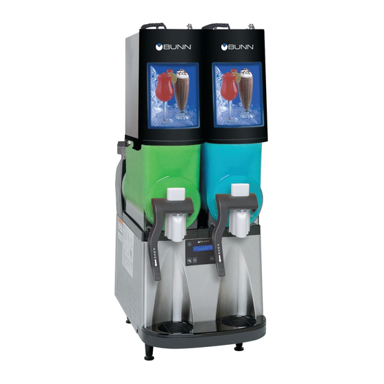
These instructions are for installing the Liquid Autofill Kits on Autofill ready ULTRA-1 and ULTRA-2 cold drink dispensers.
KIT CONTENTS
ULT-2
A. 37567.0000
1*
B. 37962.0001
1*
C. 36329.0000
D. 43120.xxxx
E.
38055.0003
2*
F.
34362.0003
4*
G. 00973.0000
4*
H. 43131.0000
I.
43145.0000
J.
00970.0000
K. 02308.0000
L.
38129.0017
M. 21275.0006
N. 01317.0000
O. 44194.0000
P.
44195.0000
* Not included in all kits.
INSTRUCTIONS
1. Unplug machine from power source before removing any panels.
2. Drain both hoppers and clean the machine if needed before proceeding.
3. Remove hoppers, drip tray, both side
panels and front panel.
37570.0002A 08/11 ©2011 Bunn-O-Matic Corporation
ULT-1
-
Circuit Board, ULTRA 2 Auto-Fill
-
Wire Harness, AF Kit
2
2
Tie, Cable-Nylon BLK 4.04"
2
1
Cover Assy, Motor LAF-BLK
1
Probe Assy, LAF
2
Bushing .156" ID x .490" OD x .12" Flg
2
Nut, KEPS #6-32
2
1
Bracket, Motor Cover Support
2
1
Bracket, Motor Cover Mounting
8
4
Nut, KEPS #8-32
4
2
Screw, Pan Head, Slotted w/serr. #8-32 x .38"
4
2
Hose, Braided .25 ID x 11.0" Lg
8
4
Clamp .406/.504" Dia.
4
2
Screw, Truss Head, Slotted #8-32 x .50"
-
1
Wire Harness (Not Auto-fill Ready)
-
1
Wire Harness (Auto-fill Ready)
4.
Remove both motor covers and locate
.50" round knock out in top right area
of plastic drum mount. Discard screws.
BUNN-O-MATIC CORPORATION
POST OFFICE BOX 3227
SPRINGFIELD, ILLINOIS 62708-3227
PHONE: (217) 529-6601 FAX: (217) 529-6644
ULTRA-1 & 2
INSTRUCTIONS FOR INSTALLING
LIQUID AUTOFILL KITS
(Continued)
5.
With a standard screwdriver and a
hammer, punch out the hole needed
for the level probe. Repeat this step
for all barrels.
Advertisement

Subscribe to Our Youtube Channel
Summary of Contents for Bunn Liquid Autofill Kits
- Page 1 ULTRA-1 & 2 INSTRUCTIONS FOR INSTALLING LIQUID AUTOFILL KITS INTRODUCTION These instructions are for installing the Liquid Autofill Kits on Autofill ready ULTRA-1 and ULTRA-2 cold drink dispensers. KIT CONTENTS ULT-2 ULT-1 A. 37567.0000 Circuit Board, ULTRA 2 Auto-Fill B. 37962.0001 Wire Harness, AF Kit C.
- Page 2 INSTRUCTIONS (Continued) 8. Reinstall the main board into the 6. Remove 4 screws holding in the main 7. Connect Auto Fill board to J-12 on the machine using the original mounting circuit board. main board. Be sure to snap the plastic screws.
- Page 3 INSTRUCTIONS (Continued) For ULTRA-1 Models that are Auto-fill ready: 15. Locate unused white and red auto-fill 16. Connect white and red wires from the valve wire connections tied in a bundle new harness (R) to white and red wires on the main wiring harness. Carefully repectively on the main harness.
- Page 4 INSTRUCTIONS (Continued) Plumbing & Water Pressure Requirements • Supply water pressure requirement is 50 – 80 psi. Syrup supply is to be 30 – 80 psi. 23. Connect syrup supply lines from BIB 22. Using supplied cable tie (C), attach the system.
-
Page 5: Setup And Calibration
INSTRUCTIONS (Continued) Set up and calibration: 29. Apply power to machine and turn on water and syrup supply. Refer to the Programming section of this manual in the Refill Threshold section to check refill for proper operation. 30. At the threshold screen, with no product in the hopper, confirm the number on the left (top) of the screen is around 250. The number on the right of the screen is factory set to 155. -
Page 6: Operating Controls
OPERATING CONTROLS (ULTRA-2 Shown) There are five of these switches that will be used for the operation of the dispenser. P3677 switch (upper left corner of the control pad) This switch is the ON/OFF toggle switch which powers up the dispenser and the LCD display. When ON the Date and Time toggle back and forth continously except during programming. -
Page 7: Programming Switches
PROGRAMMING Using the menu-driven display on the front of the dispenser, the operator has the ability to alter or modify various parameters such as beverage consistency and set day/night “ON/OFF” times. The operator is also prompted to check a variety of periodic service functions or even a step-by-step cleaning routine. There is also the opportunity to return all changes back to factory default settings. - Page 8 Delayed Refill (Late Model Dispensers with Refill Kit Installed only) This function allows the operator to dose in small amounts of new product while delaying between doses. This can help the already frozen product from becoming diluted and not ready to serve. These delay and fill times are to be determined and set based on each application as desired by the end user.
- Page 9 Auto-fill Sanitizing Instructions (With Internal Brixing System Installed) 1. Fill bucket with 4 gallons of 120 Degree F water and sanitizing solution to equal 100 ppm of available chlo- rine. Note: some installations may require more sanitizer solution to fill the supply lines completely. 2.
- Page 10 SOLE OPTION AS SPECIFIED HEREIN, TO REPAIR, REPLACEMENT OR REFUND. In no event shall BUNN be liable for any other damage or loss, including, but not limited to, lost profits, lost sales, loss of use of equipment, claims of Buyer’s customers, cost of capital, cost of down time, cost of substitute equipment, facilities or services, or any other special, incidental or consequential damages.


Need help?
Do you have a question about the Liquid Autofill Kits and is the answer not in the manual?
Questions and answers