
Related Manuals for Contec AIO-121602LN-USB


Summary of Contents for Contec AIO-121602LN-USB
- Page 1 PC-HELPER N Series for USB Multifunction DAQ Unit (16ch AI, 2ch AO, 16ch DIO) AIO-121602LN-USB Multifunction DAQ Unit (8ch AI, 2ch AO, 16ch DIO) AIO-120802LN-USB User’s Guide CONTEC CO.,LTD.
- Page 2 Check Your Package Thank you for purchasing the CONTEC product. The product consists of the items listed below. Check, with the following list, that your package is complete. If you discover damaged or missing items, contact your retailer. Product Configuration List - Unit (One of the following) …1...
-
Page 3: Copyright
No part of this document may be copied or reproduced in any form by any means without prior written consent of CONTEC CO., LTD. CONTEC CO., LTD. makes no commitment to update or keep current the information contained in this document. The information in this document is subject to change without notice. -
Page 4: Table Of Contents
Setting with the Found New Hardware Wizard ................. 17 Setting Properties Using Device Manager ................. 18 Step 4 Checking Operations with the Diagnosis Program ..............20 What is the Diagnosis Program? ....................20 Check Method ..........................20 Using the Diagnosis Program ..................... 21 AIO-121602LN-USB, AIO-120802LN-USB... - Page 5 Outline of C-LOGGER ........................55 FUNCTION Analog Input Function ........................57 1. Setting the Conversion Conditions ..................58 2. Starting/Stopping Operation ....................65 3. Monitoring the Status and Acquiring Data ................66 4. Reset ............................70 Analog Output Function ........................71 AIO-121602LN-USB, AIO-120802LN-USB...
- Page 6 Physical dimensions .......................... 91 Block Diagram ..........................92 Control Signal Timings ........................93 Control Signal Timings for Analog Input .................. 93 Control Signal Timings for Analog Output ................94 Control Signal Timings for Counter ................... 95 About Calibration ..........................96 AIO-121602LN-USB, AIO-120802LN-USB...
- Page 7 AIO-121602LN-USB, AIO-120802LN-USB...
-
Page 8: Before Using The Product
Analog I/O can be implemented in a compact system. The series consists of two different models from which you can select the best model to suit your application. The < AIO-121602LN-USB > contains the analog input (12bit, 16ch), analog output (12bit, 2ch). The < AIO-120802LN-USB > contains the analog input (12bit, 8ch), analog output (12bit, 2ch). -
Page 9: Magnet
We offer a dedicated library [ML-DAQ], which allows you to use this product on MATLAB by The MathWorks as well as another dedicated library [VI-DAQ], which allows you to use the product on LabVIEW. These dedicated libraries are available, free of charge (downloadable), on our web site. AIO-121602LN-USB, AIO-120802LN-USB... -
Page 10: Support Software
1. Before Using the Product Support Software You should use CONTEC support software according to your purpose and development environment. Windows version of analog I/O driver API-AIO(WDM) [Stored on the bundled CD-ROM driver library API-USBP(WDM)] It is the library software, and which supplies command of hardware produced by our company in the form of standard Win32 API function (DLL). -
Page 11: Customer Support
You can download updated driver software and differential files as well as sample programs available in several languages. Note! For product information Contact your retailer if you have any technical question about a CONTEC product or need its price, delivery time, or estimate information. Limited One-Year Warranty CONTEC products are warranted by CONTEC CO., LTD. -
Page 12: Safety Precautions
Even when using this product continuously, be sure to read the manual and understand the contents. Do not modify this product. CONTEC will bear no responsibility for any problems, etc., resulting from modifying this product. Regardless of the foregoing statements, CONTEC is not liable for any damages whatsoever (including damages for loss of business profits) arising out of the use or inability to use this CONTEC product or the information contained herein. - Page 13 Turn Quantity Installation Site E04SR301334 SEIWA on USB cable at product side E04SR301334 SEIWA on signal cable at product side(CN2, CN3) Image diagram Ferrite core Cable TURN : 1 TURN : 2 TURN : 4 TURN : 3 AIO-121602LN-USB, AIO-120802LN-USB...
- Page 14 WARNING TO USER Change or modifications not expressly approved the manufacturer can void the user's authority to operate this equipment. AIO-121602LN-USB, AIO-120802LN-USB...
-
Page 15: Environment
Inspect the product periodically as follows to use it safely. CAUTION Check that the ventilation slit has no obstruction and has no dust or foreign matter adhering. Moreover, if there is the slit on the case side, please confirm it to the slit similarly. AIO-121602LN-USB, AIO-120802LN-USB... -
Page 16: Storage
(3) Store the package at room temperature at a place free from direct sunlight, moisture, shock, vibration, magnetism, and static electricity. Disposal When disposing of the product, follow the disposal procedures stipulated under the relevant laws and municipal ordinances. AIO-121602LN-USB, AIO-120802LN-USB... - Page 17 1. Before Using the Product AIO-121602LN-USB, AIO-120802LN-USB...
-
Page 18: Setup
The following shows the basic flow for installing product. Connecting the Product Setting Properties Using Installing the Software - Connecting the PC Device Manager - API-USBP(WDM) - Setting the Device Development Environment Name. - C-LOGGER Page 13 Page 16 Page 18 AIO-121602LN-USB, AIO-120802LN-USB... -
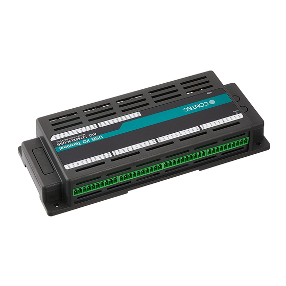
Page 19: Step 1 Setting The Hardware
This section describes how to set up the product and how to connect it to a PC. Name of each parts LED indicator The above figure has installed the USB cable attachment. Figure 2.1. Name of each parts (Front side) AIO-121602LN-USB, AIO-120802LN-USB... -
Page 20: Step 2 Initializing The Software
Please set up the supplied CD-ROM if it has not been set up. The menu starts automatically. If the menu do not start, launch X:AUTORUN.EXE (X:CD-ROM drive) from [Run…] in Start menu. The screen design may be different. AIO-121602LN-USB, AIO-120802LN-USB... -
Page 21: Installation Of Api-Usbp(Wdm) Development Environment
(1) Clicking on “Install Development or Execution Environment”. [API-USBP(WDM) Installer] dialog box displays. (2) Selecting “Advanced Analog I/O driver”. (3) Clicking on “Continue” Button. Please perform installation following the directions on the screen. And thus the installation is completed. The screen design may be different. AIO-121602LN-USB, AIO-120802LN-USB... -
Page 22: Installing C-Logger
(1) Clicking on “C-LOGER”. [Choose Setup Language] dialog box displays. (2) Selecting “English”. (3) Clicking on “OK” Button. Please perform installation following the directions on the screen. And thus the installation is completed. The screen design may be different. AIO-121602LN-USB, AIO-120802LN-USB... -
Page 23: Step 3 Installing The Hardware
The USB cable attachment cannot be used excluding an attached cable. When the USB cable attachment is being used, do not perform removing and connecting the USB cable on the unit side repeatedly. This may damage the USB cable attachment or yourself. AIO-121602LN-USB, AIO-120802LN-USB... -
Page 24: Setting With The Found New Hardware Wizard
Detect setup information from supplied CD automatically for installing USB driver. * The name of the connected product will be displayed. - AIO-121602LN-USB - AIO-120802LN-USB Point Please specify the path for supplied CD as follows in the case of failure in detecting automatically. -
Page 25: Setting Properties Using Device Manager
From [Start] menu, click on [Settings]-[Control Panel]-[System] and then click on [Device Manager] button in [Hardware] tab. * The name of the connected product will be displayed. - AIO-121602LN-USB - AIO-120802LN-USB In the case of Windows 98/Me Right-click on [My Computer] and select [Properties] to start device manager. - Page 26 Open [Common Settings] tab and enter arbitrary name in the editing box for device name. (Default name also can be used.) * The name of the connected product will be displayed. - AIO-121602LN-USB - AIO-120802LN-USB * The product-specific number will be displayed as the serial number. CAUTION USB driver can not be used without settings.
-
Page 27: Step 4 Checking Operations With The Diagnosis Program
Input data remains indeterminate when no input pin is connected. The input pin for the channel not connected to the signal source must be connected to the analog ground. For details, see “Chapter 3 External Connection”. < Analog Output > Figure 2.5. Connection diagram (Analog Output) AIO-121602LN-USB, AIO-120802LN-USB... -
Page 28: Using The Diagnosis Program
Starting the Diagnosis Program Click [Diagnosis] on the Properties page to start the diagnosis program. * The name of the connected product will be displayed. - AIO-121602LN-USB - AIO-120802LN-USB * The name of the connected product will be displayed. - AIO-121602LN-USB... - Page 29 Clicking the lower row of switches turns the digital output bits ON or OFF. Counter input Selecting a counter channel displays the count value and state of that counter channel. Clicking the zero clear buttons resets the count to zero. AIO-121602LN-USB, AIO-120802LN-USB...
- Page 30 Clicking [Diagnosis Report] prompts you to specify where to save the report text file. * The name of the connected product will be displayed. - AIO-121602LN-USB - AIO-120802LN-USB (2) The diagnosis report contains the following data. - Version of OS...
-
Page 31: Setup Troubleshooting
Refer to the source code for the sample programs. The OS does not boot correctly or does not detect the device correctly. Refer to the "Troubleshooting" section of API-AIO(WDM) HELP. If your problem cannot be resolved Contact your retailer. AIO-121602LN-USB, AIO-120802LN-USB... -
Page 32: Connection And Installation
Figure 3.1. Mounting on a DIN Rail < 2 / 3 > (3) Push the fixing hook up using a slotted screwdriver to make it lockable. Figure 3.1. Mounting on a DIN Rail < 3 / 3 > AIO-121602LN-USB, AIO-120802LN-USB... - Page 33 Removing the unit from the DIN rail < 2 / 3 > (3) By lifting this unit, you can easily remove it from the DIN rail. Figure 3.2. Removing the unit from the DIN rail < 3 / 3 > AIO-121602LN-USB, AIO-120802LN-USB...
-
Page 34: Desktop Installation
The rubber feet can be mounted in their mounting holes as shown in the following figure. Figure 3.3. Mounting the rubber feet Wall Installation To mount the product on the wall, purchase the commercially available screw (fitting for φ3.5) separately. Figure 3.4. Wall Installation AIO-121602LN-USB, AIO-120802LN-USB... -
Page 35: Installation Using The Magnet
Figure 3.5. Mounting the magnet To remove the magnet, slide the magnet in the direction of arrow 1 as shown in the following figure, and then lift it out in the direction of arrow 2. Figure 3.6. Removing the magnet AIO-121602LN-USB, AIO-120802LN-USB... - Page 36 3. Connection and Installation Mounting onto the steel wall Mount the product directly onto the steel wall. Pull it gently after mounting to confirm that it will not drop off from the body. Figure 3.7. Mounting onto the steel wall AIO-121602LN-USB, AIO-120802LN-USB...
-
Page 37: Installation Conditions
Vertical installation Horizontal installation Installation on a ceiling Figure 3.9. Screws / magnet fixation CAUTION When using the product in a high temperature environment, cool it by blowing air even when the temperature is within the specified range. AIO-121602LN-USB, AIO-120802LN-USB... - Page 38 Secure a distance of at least 50mm between the top of the main unit (single use) and any surrounding objects. Do not locate the unit in a fully enclosed housing. Figure 3.10. Spacing between the unit and any surrounding objects AIO-121602LN-USB, AIO-120802LN-USB...
-
Page 39: Connection Method
Releasing the orange button after the wire is inserted fixes the cable. Compatible wires are AWG 28 - 16. Figure 3.11. Connecting an Interface Connector and Connectors That Can Be Used CAUTION Removing the connector plug by grasping the cable can break the wire. AIO-121602LN-USB, AIO-120802LN-USB... -
Page 40: Signal Layout On The Interface Connector
3. Connection and Installation Signal Layout on the Interface Connector The unit can be connected to an external device using 10-pin connectors that is provided on the unit face. AIO-121602LN-USB < Single-Ended Input > Signal Signal Signal Meaning Meaning Meaning... - Page 41 Common digital ground for digital I/O signals, external trigger inputs, Digital Ground external sampling clock inputs, and counter I/O signals. Reserved Reserved pin. N.C. No connection to this pin. Figure 3.12. Pin Assignments of Interface Connector < AIO-121602LN-USB > < Single-Ended Input > AIO-121602LN-USB, AIO-120802LN-USB...
- Page 42 3. Connection and Installation AIO-121602LN-USB < Differential Input > Signal Signal Signal Meaning Meaning Meaning name name name AI00 Analog Input 00[+] AO00 Analog Output 00 DIO00 Digital Input/Output 00 Analog Ground AI01 Analog Input 00[- ] AGND DIO01 Digital Input/Output 01...
- Page 43 Common digital ground for digital I/O signals, external trigger inputs, Digital Ground external sampling clock inputs, and counter I/O signals. Reserved Reserved pin. N.C. No connection to this pin. Figure 3.13. Pin Assignments of Interface Connector < AIO-121602LN-USB > < Differential Input > AIO-121602LN-USB, AIO-120802LN-USB...
- Page 44 DIO12 Digital Input/Output 12 AI External Start AISTA DIO13 Digital Input/Output 13 Trigger Input AI External Stop AISTP DIO14 Digital Input/Output 14 Trigger Input AI External Sampling AICLK DIO15 Digital Input/Output 15 Clock Input DGND DigitalGround DGND DigitalGround AIO-121602LN-USB, AIO-120802LN-USB...
- Page 45 Count match output signal for counter. Common digital ground for digital I/O signals, external trigger inputs, Digital Ground Reserved Reserved pin. N.C. No connection to this pin. Figure 3.14. Pin Assignments of Interface Connector < AIO-120802LN-USB > < Single-Ended Input > AIO-121602LN-USB, AIO-120802LN-USB...
- Page 46 DIO12 Digital Input/Output 12 AI External Start AISTA DIO13 Digital Input/Output 13 Trigger Input AI External Stop AISTP DIO14 Digital Input/Output 14 Trigger Input AI External Sampling AICLK DIO15 Digital Input/Output 15 Clock Input DGND DigitalGround DGND DigitalGround AIO-121602LN-USB, AIO-120802LN-USB...
- Page 47 Count match output signal for counter. Digital Ground Common digital ground for digital I/O signals, external trigger inputs, Reserved Reserved pin. N.C. No connection to this pin. Figure 3.15. Pin Assignments of Interface Connector < AIO-120802LN-USB > < Differential Input > AIO-121602LN-USB, AIO-120802LN-USB...
-
Page 48: Analog Input Signal Connection
An input pin may fail to obtain input data normally when the signal source connected to the pin has high impedance. If this is the case, change the signal source to one with lower output impedance or insert a high-speed amplifier buffer between the signal source and the analog input pin to reduce the effect. AIO-121602LN-USB, AIO-120802LN-USB... -
Page 49: Differential Input
An input pin may fail to obtain input data normally when the signal source connected to the pin has high impedance. If this is the case, change the signal source to one with lower output impedance or insert a high-speed amplifier buffer between the signal source and the analog input pin to reduce the effect. AIO-121602LN-USB, AIO-120802LN-USB... -
Page 50: Analog Output Signal Connection
Do not connect an analog output signal to any other analog output, either on this product or on an external device, as this may cause a fault on this product. Analog output signal outputs hundreds of micro voltages when USB cable is inserted. AIO-121602LN-USB, AIO-120802LN-USB... -
Page 51: Connecting I/O Signals
When "1" is output to a relevant bit, the corresponding LED comes on. When "0" is output to the bit, in contrast, the LED goes out. Figure 3.23. Connection Example Using DIO00 for Input and DIO08 for Output CAUTION Take care not to short the outputs to digital ground as this may cause a fault. AIO-121602LN-USB, AIO-120802LN-USB... -
Page 52: Counter Signals And Control Signals Connection
If connected to each output, a pull-up resistor must be about 10kΩ to pull up with a 5V power source. Each input accepts 5V TTL signals. Reference For the operation timings for control signal input, see “Control Signal Timings” in Chapter 6 “Hardware”. AIO-121602LN-USB, AIO-120802LN-USB... - Page 53 3. Connection and Installation AIO-121602LN-USB, AIO-120802LN-USB...
-
Page 54: Application Development
4. Application Development Please reference to online help and sample program when developing applications. Reference to Online Help Click on [Programs]-[CONTEC API-USBP(WDM)]-[API-USBP(WDM) Help] from [Start] menu. The information for application development, such as function reference is provided in [API-USBP(WDM) Help]. -
Page 55: Sample Program
(The default path is Program Files\CONTEC~) Sample programs in all language are provided here. To run a sample program, click on [Programs]- [CONTEC API- USBP(WDM)]-[AIO]-[Sample Name] from [Start] menu. Distributing Developed Application Please distribute the developed application with USB driver in supplied CD-ROM. -
Page 56: Use Of Utility Program
Program for measuring the executive speed of function is a program that can measure the executive time of some main functions. To use the program for measuring the executive speed of function, please click the button "Measure tool..." from CONTEC DIAGNOSIS PROGRAM. * The name of the connected product will be displayed. - Page 57 Since the notification of a sampling clock error event is sent, please make use of it for the conversion spec measurement under various conversion conditions. * The name of the board you have just added is displayed. - AIO-121602LN-USB - AIO-120802LN-USB 256K AIO-121602LN-USB, AIO-120802LN-USB...
- Page 58 The cycle of the clock is too fast when converting it at the external clock. Moreover, the cause by noise etc. is also concerned. Buffer overflow: The memory overflows since the conversion speed is too fast compared with the one at which data is inputted. (4) Click the “stop” button, and measurement stops. AIO-121602LN-USB, AIO-120802LN-USB...
- Page 59 As an event is also generated if a sampling clock error occurs, you can use the utility to test the conversion operation under a range of different conditions. * The name of the connected product will be displayed. - AIO-121602LN-USB - AIO-120802LN-USB 128K Step to use (1) Use the combo box at the top left of the window to select the device name of the device to use, then click the [Set] button.
- Page 60 When the application is measuring with internal clock, sampling clock is too fast to process. When the application is measuring with External clock, clock cycle is too fast. Moreover, noise is being considered. (4) The measuring is stopping after clicked the button of [Stop]. AIO-121602LN-USB, AIO-120802LN-USB...
-
Page 61: Returning To Initial State
(1) Deleting Device form Device Manager. * The name of the connected product will be displayed. - AIO-121602LN-USB - AIO-120802LN-USB (2) Drawing USB cable from a PC (3) Uninstalling Driver Select [CONTEC API-AIO(WDM) driver] from [My Computer]-[Control Panel]-[Add/Remove Programs]. (4) Restarting AIO-121602LN-USB, AIO-120802LN-USB... -
Page 62: About C-Logger
Setting acquirement conditions easily with wizard Operating intuitively with file viewer and property viewer Saving to file automatically for long-time and mass-data acquirement Displaying Graph in 2 Screens: Whole and Zoom Abundant Function for Customization For details, refer to the C-LOGGER Users Guide. AIO-121602LN-USB, AIO-120802LN-USB... - Page 63 5. About C-LOGGER AIO-121602LN-USB, AIO-120802LN-USB...
-
Page 64: Function
Start Condition Channel Stop Condition Channel Event conversion order Range Data transfer method Memory format Repeat 2. Starting/Stopping Operation Start Stop 3. Monitoring the Status and Acquiring Data Status Sampling Repeat Data acquisition Conversion data 4.Reset Status Memory AIO-121602LN-USB, AIO-120802LN-USB... -
Page 65: Setting The Conversion Conditions
For channel numbers, see “How to connect the connectors” to “Connector Pin Assignment” in Chapter 3 "External Connection". The channel selection specifies the channel number or the number of channels (channel consecutive from channel 0) in which it wants to convert AD. AIO-121602LN-USB, AIO-120802LN-USB... - Page 66 ”Range” means the range of voltages at which analog input can be performed Software setup of the range is not required as this board uses a fixed range of voltages. : ±10V, ±5V, ±2.5V, 0 - 10V AIO-121602LN-USB : ±10V, ±5V, ±2.5V, 0 - 10V AIO-120802LN-USB AIO-121602LN-USB, AIO-120802LN-USB...
- Page 67 The device buffer mode provides function that allows the number of items of conversion data using the number of sampling times as a unit to obtain the number of items of conversion data directly from the voltage. Device buffer mode AIO-121602LN-USB, AIO-120802LN-USB...
- Page 68 The ring memory is used to obtain data where conversion has stopped due to some event, usually without obtaining data in the normal state. AIO-121602LN-USB, AIO-120802LN-USB...
- Page 69 The sampling clock controls the sampling frequency. You can select both the internal sampling clock and external sampling clock. Internal sampling clock The clock signal from the on-board clock generator is used. External sampling clock The edge of the digital signal input from an external device is used for the sampling clock. AIO-121602LN-USB, AIO-120802LN-USB...
- Page 70 The board starts waiting for an external control signal as soon as the operation start command is output. Sampling and data transfer to memory start when the specified edge (rising edge or falling edge) is input from the external control signal. AIO-121602LN-USB, AIO-120802LN-USB...
- Page 71 The board starts waiting for an external control signal as soon as the operation start command is output. Sampling and data transfer to memory start when the specified edge (rising edge or falling edge) is input from the external control signal. AIO-121602LN-USB, AIO-120802LN-USB...
-
Page 72: Starting/Stopping Operation
AD conversion error event This event occurs when conversion stops due to an AD conversion error. 2. Starting/Stopping Operation Sampling is started by the software command. Once started, sampling can be stopped by the software command at any timing. AIO-121602LN-USB, AIO-120802LN-USB... -
Page 73: Monitoring The Status And Acquiring Data
ON. This error stops sampling. Sampling The number of sampled items of input data stored in memory can be obtained by the software command. Repeat The current repeat count can be obtained by the software command. AIO-121602LN-USB, AIO-120802LN-USB... - Page 74 When data is acquired from the memory, the free memory space increases by that data size. When data is acquired next, the oldest one of the existing data items is taken from the memory in the same way. The FIFO memory deletes data once that data is acquired. AIO-121602LN-USB, AIO-120802LN-USB...
- Page 75 (shaded portion below). The larger the number of samples taken, the older the data item acquired first. As the ring memory retains data even after that data is acquired, you can fetch the same data any number of times. AIO-121602LN-USB, AIO-120802LN-USB...
- Page 76 +5.002V 2049 +5.000V 2048 +4.998V 2047 Ex.: When AD conversion data 3072 is input at a resolution of 12bit in the 0 - 10V range Voltage = 3072 x (10 - 0) ÷ 4096 + 0 = 7.5 AIO-121602LN-USB, AIO-120802LN-USB...
-
Page 77: Reset
Resets the conversion data in memory. Resets the repeat count to 0. Resets the sampling count to 0 when a stop trigger is input. Resets the buffer overflow status. Resets the status information for the specified data save count. AIO-121602LN-USB, AIO-120802LN-USB... -
Page 78: Analog Output Function
Conditions Resolution Clock Channel Start Condition Range Stop Condition Output data Event Data transfer method Memory format Repeat Setting data 2. Starting/Stopping Operation Start Stop 3. Monitoring the Status and Acquiring Data Status Sampling 4. Reset Status Memory AIO-121602LN-USB, AIO-120802LN-USB... -
Page 79: Setting The Conversion Conditions
"Range" means the range of voltages at which analog output can be performed. Software setup of the range is not required as this board uses a fixed range of voltages. : ±10V, ±5V, 0 - 10V, 0 - 5V AIO-121602LN-USB : ±10V, ±5V, 0 - 10V, 0 - 5V AIO-120802LN-USB AIO-121602LN-USB, AIO-120802LN-USB... - Page 80 Output data(12-bit) +9.998V 4095 +5.002V 2049 +5.000V 2048 +4.998V 2047 Ex.: When 3V is output at a resolution of 12bit in the 0 -10V range Output data = (3 - 0) 4096 ÷ (10 - 0) = 1228.8 * AIO-121602LN-USB, AIO-120802LN-USB...
- Page 81 When conversion starts, the device starts outputting the output data. The device buffer can operate as FIFO or RING memory. Device buffer mode handles conversion data by sampling count and API functions are provided to retrieve conversion data directly as voltage values. Device buffer mode AIO-121602LN-USB, AIO-120802LN-USB...
- Page 82 An error occurs if the volume of data exceeds the memory size. However, this error does not stop analog output if it is in progress. Ring format Use ring format if you wish to output a repeated pattern like that shown below. AIO-121602LN-USB, AIO-120802LN-USB...
- Page 83 The number of repetitions is set by software and sampling is repeated for the specified number of times. You can also specify that operation continue indefinitely. If set to repeat indefinitely, analog output operation is stopped by outputting a analog output stop command by software. AIO-121602LN-USB, AIO-120802LN-USB...
- Page 84 When using FIFO format, setting data to memory is always performed from the most recent data. New data can be added during conversion. Procedure for RING format When using ring format, a ring memory area large enough for the data to be set is reserved. Data cannot be modified during DA conversion. AIO-121602LN-USB, AIO-120802LN-USB...
- Page 85 The following events can be used in combination depending on the specifications and purpose of the application. ”DA conversion start condition satisfied” event This event occurs when the DA conversion start condition is satisfied. The event is nullified when the conversion start condition is “software”. AIO-121602LN-USB, AIO-120802LN-USB...
-
Page 86: Starting/Stopping Operation
Specified number of data outputs This status turns ON when the output data set in memory has reached a predefined number of samples. Sampling clock error This error occurs when the sampling clock period is too short. AIO-121602LN-USB, AIO-120802LN-USB... -
Page 87: Reset
This command resets the following memory related states. Resets the conversion data in memory. Resets the repeat count to 0. Resets the sampling count to 0 when a stop trigger is input. Resets the status information for the specified data save count. AIO-121602LN-USB, AIO-120802LN-USB... -
Page 88: Counter Function
Input signal The external clock can be selected as the counter input signal. Digital filter A digital filter can be used on external input bits. The filter time can be set to "don't use", 1µs, 128µs, 16ms by software. AIO-121602LN-USB, AIO-120802LN-USB... -
Page 89: Starting/Stopping Operation
Execution of driver processing may not be able to keep up if multiple count match events occur within a short time period. In this case, the counter operation error status turns ON and counter operation stops. Data acquisition The current count value can be read using a software command. AIO-121602LN-USB, AIO-120802LN-USB... -
Page 90: Reset
4. Reset Various states can be reset by executing the following reset commands: Counter reset Resets the counter. This restores the counter to its state after power on. Status Resets the compare count match status and overrun status. AIO-121602LN-USB, AIO-120802LN-USB... -
Page 91: Digital Input Function
Byte data = 85(55H) Digital filter A digital filter can be used on the input bits. The filter time can be set to "don't use", 1µs, 128µs,16ms by software. CAUTION When the PC is turned on, All is set to input. AIO-121602LN-USB, AIO-120802LN-USB... -
Page 92: Digital Output Function
Ex. Output of bit 7 (ON), bit 6 (OFF), bit 5 (ON), bit 4 (OFF), bit3 (ON), bit 2 (OFF), bit 1 (ON) and bit 0 (OFF) Byte data = 170 (AAH) CAUTION The level is Low after it was set to output. AIO-121602LN-USB, AIO-120802LN-USB... - Page 93 6. Function AIO-121602LN-USB, AIO-120802LN-USB...
-
Page 94: About Hardware
7. About Hardware About Hardware Hardware specification Table 7.1. Specification < AIO-121602LN-USB > < 1 / 2 > Item Specification Analog input Isolated specification Un-Isolated Input type Single-Ended Input or Differential Input Number of input 16channels (Single-Ended Input), 8channels (Differential Input) channels Bipolar ±10V, ±5V, ±2.5V... - Page 95 7. About Hardware Table 7.1. Specification < AIO-121602LN-USB > < 2 / 2 > Item Specification Digital I/O Number of I/O Channels 16-bit input lines, 8-bit input/output lines, 16-bit output lines (programmable) I/O signal level TTL level (positive logic) Counter...
- Page 96 TTL level (Rising or falling edge can be selected by software) External stop signal TTL level (Rising or falling edge can be selected by software) External clock signal TTL level (Rising or falling edge can be selected by software) AIO-121602LN-USB, AIO-120802LN-USB...
- Page 97 *4 : The USB transfer speed depends on the host PC environment used (OS and USB host controller). *5 : As a USB hub is also counted as one device, you cannot just connect 127 USB terminals. *6 : To suppress the heating, ensure that there are spaces for ventilation (about 5cm) around this product. AIO-121602LN-USB, AIO-120802LN-USB...
-
Page 98: Physical Dimensions
7. About Hardware Physical dimensions Figure 7.1. Physical dimensions < AIO-121602LN-USB > Figure 7.2. Physical dimensions < AIO-120802LN-USB > AIO-121602LN-USB, AIO-120802LN-USB... -
Page 99: Block Diagram
7. About Hardware Block Diagram Figure 7.3. Block Diagram < AIO-121602LN-USB > Figure 7.4. Block Diagram < AIO-120802LN-USB > AIO-121602LN-USB, AIO-120802LN-USB... -
Page 100: Control Signal Timings
Hold time of sampling stop (Rising edge) nsec Set up time of sampling stop (Falling edge) nsec Hold time of sampling stop (Falling edge) nsec CAUTION The times listed in Table 7.3 are for standard operating conditions. AIO-121602LN-USB, AIO-120802LN-USB... -
Page 101: Control Signal Timings For Analog Output
Hold time of sampling stop (Rising edge) nsec Set up time of sampling stop (Falling edge) nsec Hold time of sampling stop (Falling edge) nsec CAUTION The times listed in Table 7.4 are for standard operating conditions. AIO-121602LN-USB, AIO-120802LN-USB... -
Page 102: Control Signal Timings For Counter
Unit Set up time of counter input (Rising edge) nsec Hold time of sampling start (Rising edge) nsec Pulse width of counter output signal 1000 nsec CAUTION The times listed in Table 7.5 are for standard operating conditions. AIO-121602LN-USB, AIO-120802LN-USB... -
Page 103: About Calibration
Click the [Calibration] button on the property page for the device to start the calibration program. * The name of the board you have just added is displayed. - AIO-121602LN-USB - AIO-120802LN-USB Proceed with connecting the calibration equipment and performing the calibration in accordance with the instructions displayed by the calibration program. - Page 105 3-9-31, Himesato, Nishiyodogawa-ku, Osaka 555-0025, Japan Japanese http://www.contec.co.jp/ English http://www.contec.com/ Chinese http://www.contec.com.cn/ No part of this document may be copied or reproduced in any form by any means without prior written consent of CONTEC CO., LTD. [09062013] [09012011] Management No. NA90061 [09062013_rev3] Parts No.
Need help?
Do you have a question about the AIO-121602LN-USB and is the answer not in the manual?
Questions and answers