
Related Manuals for Contec CNT32-4MT


Summary of Contents for Contec CNT32-4MT
- Page 1 PC-HELPER 4ch 32Bit Up/Down High-Speed Counter Board for Low Profile PCI CNT32-4MT(LPCI) User’s Guide CONTEC CO.,LTD.
- Page 2 Check Your Package Thank you for purchasing the CONTEC product. The product consists of the items listed below. Check, with the following list, that your package is complete. If you discover damaged or missing items, contact your retailer. Product Configuration List - Board [CNT32-4MT(LPCI)] …1...
-
Page 3: Copyright
No part of this document may be copied or reproduced in any form by any means without prior written consent of CONTEC CO., LTD. CONTEC CO., LTD. makes no commitment to update or keep current the information contained in this document. The information in this document is subject to change without notice. -
Page 4: Table Of Contents
When Using API-CNT(WDM) ....................11 When Using API-CNT(98/PC) ....................12 Executing the Installation ......................13 Step 2 Setting the Hardware......................14 Replacing the Bracket........................ 14 Parts of the Board and Factory Defaults ................... 15 Setting the Board ID ........................15 CNT32-4MT(LPCI) - Page 5 Types and Operations of Pulse Signals .................... 43 Types of pulse signals........................ 43 2-phase Input ..........................43 Single-phase Input ........................44 Single-phase Input with Gate Control Attached ............... 44 Multiplication of Count Input....................45 Synchronous Clear........................45 Asynchronous Clear........................46 Phase-Z/CLR Input ........................46 CNT32-4MT(LPCI)
- Page 6 Timer............................65 ABOUT SOFTWARE CD-ROM Directory Structure ......................67 About Software for Windows......................68 Accessing the Help File......................69 Using Sample Programs ......................70 Uninstalling the API Function Libraries ................... 72 ABOUT HARDWARE Hardware specification........................73 Block Diagram..........................75 CNT32-4MT(LPCI)
- Page 7 CNT32-4MT(LPCI)
-
Page 8: Before Using The Product
The application for this board can transfer data between the board and the PC at high speed using PCI bus mastering. <Example > - Detecting a position of the table of a machine tool - Detecting a change in weight CNT32-4MT(LPCI) Tool Processing thing Rack Encoder... -
Page 9: Support Software
Visual Basic, Visual C++, Visual C#, Delphi, C++ Builder You can download the updated version from the CONTEC’s Web site (http://www.contec.com/apipac/). For more details on the supported OS, applicable language and new information, please visit the CONTEC’s Web site. Cable & Connector (Option) Shielded cable for CardBus counter input card : CNT-68M/50M (0.5m) -
Page 10: Customer Support
You can download updated driver software and differential files as well as sample programs available in several languages. Note! For product information Contact your retailer if you have any technical question about a CONTEC product or need its price, delivery time, or estimate information. Limited Three-Years Warranty CONTEC Interface products are warranted by CONTEC CO., LTD. -
Page 11: Safety Precautions
WARNING indicates a potentially hazardous situation which, if not avoided, could WARNING result in death or serious injury. CAUTION indicates a potentially hazardous situation which, if not avoided, may CAUTION result in minor or moderate injury or in property damage. CNT32-4MT(LPCI) -
Page 12: Handling Precautions
Even when using the product continuously, be sure to read the manual and understand the contents. Do not modify the product. CONTEC will bear no responsibility for any problems, etc., resulting from modifying this product. Regardless of the foregoing statements, CONTEC is not liable for any damages whatsoever (including damages for loss of business profits) arising out of the use or inability to use this CONTEC product or the information contained herein. -
Page 13: Environment
(3) Store the package at room temperature at a place free from direct sunlight, moisture, shock, vibration, magnetism, and static electricity. Disposal When disposing of the product, follow the disposal procedures stipulated under the relevant laws and municipal ordinances. CNT32-4MT(LPCI) -
Page 14: Setup
For setting up software other than API-PAC(W32), refer to the user’s guide for that software. See also the following parts of this user’s guide as required. This chapter Step 2 Setting the Hardware This chapter Step 3 Installing the Hardware Chapter 3 External Connection Chapter 6 About Hardware CNT32-4MT(LPCI) -
Page 15: Using The Board Under An Os Other Than Windows
Using the Board under an OS Other than Windows For using the board under an OS other than Windows, see the following parts of this user’s guide. This chapter Step 2 Setting the Hardware Chapter 3 External Connection Chapter 6 About Hardware CNT32-4MT(LPCI) -
Page 16: Step 1 Installing The Software
OS and devices in the future but will not support Windows NT 4.0, Windows 95, ISA bus. Use API-CNT(98/PC) if your operating environment contains such an unsupported piece of software or hardware. Check the following selection guide to easily select the driver to be used. CNT32-4MT(LPCI) -
Page 17: Starting The Install Program
If the panel does not appear, run (CD-ROM drive letter):\AUTORUN.exe. (3) Click on the [Install Development or Execution Environment] button. CAUTION Before installing the software in Windows 7, Server 2008, Vista, XP, Server 2003 and 2000, log in as a user with administrator privileges. CNT32-4MT(LPCI) -
Page 18: When Using Api-Cnt(Wdm)
(3) Click on the [Install] button. Clicking the [API-CNT] button displays detailed information about API-CNT(WDM) and API-CNT(98/PC). Run the installation (1) Complete the installation by following the instructions on the screen. (2) The Readme file appears when the installation is complete. CNT32-4MT(LPCI) -
Page 19: When Using Api-Cnt(98/Pc)
(1) The following dialog box appears to select “Driver to install” and “Install option”, “Usage of driver library”. (2) Select “Classic Counter input driver”. (3) Click on the [Install] button. Clicking the [API-CNT] button displays detailed information about API-CNT(WDM) and API-CNT(98/PC). CNT32-4MT(LPCI) -
Page 20: Executing The Installation
2) Click on the [Finish] button. Go to Step 2 to set and plug the hardware. *When the hardware has already been installed: Check “Perform a hardware setup now”, then go to Step 4 “Initializing the Software”. You have now finished installing the software. CNT32-4MT(LPCI) -
Page 21: Step 2 Setting The Hardware
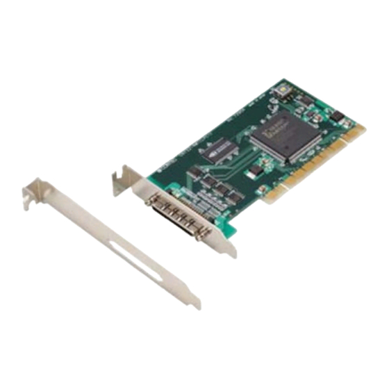
Bracket for the PCI Remove the screws and replace the low-profile PCI bracket with the standard PCI bracket. Bracket for the Low Profile PCI Screws Use a standard screwdriver to attach and detach the screws. Figure .2.1. Replacing the Bracket CNT32-4MT(LPCI) -
Page 22: Parts Of The Board And Factory Defaults
Setting Procedure To set the board ID, use the rotary switch on the board. Turn the SW1 knob to set the board ID as shown below. BOARD ID Factory setting: (Board ID = 0) Figure 2.3. Board ID Settings (SW1) CNT32-4MT(LPCI) -
Page 23: Plugging The Board
Be sure that the personal computer power is turned off. Make sure that your PC or expansion unit can supply ample power to all the boards installed. Insufficiently energized boards could malfunction, overheat, or cause a failure. Power supply from the PCI bus slot at +5V is required. CNT32-4MT(LPCI) -
Page 24: Step 3 Installing The Hardware
In this case, you must check the resource settings. When Using API-CNT(WDM) (1) The “Found New Hardware Wizard” will be started. Select “No, not this time” and then click the “Next” button. CNT32-4MT(LPCI) - Page 25 When the model name of hardware is displayed, select “Install the software automatically [Recommended]” and then click on the “Next” button. Source folder The setup information (INF) file is contained in the following folder on the bundled CD-ROM. \INF\Wdm\Cnt \INF\Wdm\Cnt CNT32-4MT(LPCI)
-
Page 26: When Using Api-Cnt(98/Pc)
2. Setup * The name of the board you have just added is displayed. - CNT32-4MT(LPCI) You have now finished installing the hardware. When Using API-CNT(98/PC) (1) The “Found New Hardware Wizard” will be started. Select “Install from a list or specific location (Advanced)”, then click on the [Next] button. - Page 27 The setup information (INF) file is contained in the following folder on the bundled CD-ROM. Windows 7, Server 2008, Vista, XP, Server 2003, 2000 \INF\Win2000\Cnt\PCI Windows Me, 98, 95 \INF\Win95\Cnt\PCI Example of specifying the folder for use the CNT32-4MT(LPCI) under Windows XP \INF\Win2000\Cnt\PCI CNT32-4MT(LPCI)
- Page 28 Windows Logo testing, and it can be ignored without developing any problem with the operation of the board. In this case, click on the [Continue Anyway] button. * The name of the board you have just added is displayed. - CNT32-4MT(LPCI) You have now finished installing the hardware. CNT32-4MT(LPCI)
-
Page 29: Step 4 Initializing The Software
The driver library requires the initial setting to recognize the execution environment. It is called the initialization of the driver library. Invoking API-TOOL Configuration (1) Open the Start Menu, then select “Programs” – “CONTEC API-PAC(W32)” – “API-TOOL Configuration”. * The name of the board you have just added is displayed. -
Page 30: Step 5 Checking Operations With The Diagnosis Program
The output pulses are LVTTL-level outputs fixed at 100 kHz. The board can also internally output test pulses to each counter channel without supplying them to the outside. In that case, the board outputs two-phase pulses to all channels at the same time. CNT32-4MT(LPCI) -
Page 31: Check Method 2: Checking The Board Single-Handedly (With External Connection)
If the board fails to perform counting normally by check method 2, its input circuit may be defective. Test pulse output circuit and its sample connection (TPOA and TPOB) CNT32-4MT(LPCI) has one test pulse output for phase-A and another for phase-B for self-diagnosis purposes. The output pulses are LVTTL-level output at fixed 100 kHz. -
Page 32: Check Method 3: Checking The Board Using An External Device
(Connector pin No.) Pull up (32 pin) Phase-A Phase-A (1 pin) Phase-B (2 pin) Phase-B Phase-Z (3 pin) Phase-Z Encoder GND (35 pin) Shield Pin numbers in the diagram shows those of connector on the board. Figure 2.5. Connection diagram CNT32-4MT(LPCI) -
Page 33: Using The Diagnosis Program
Click the [Diagnosis] button on the device property page to start the diagnosis program. Starting the Diagnosis Program for Use of API-CNT(98/PC) Select the board in the API-TOOL Configuration windows, then run the Diagnosis Program. * The name of the board you have just added is displayed. - CNT32-4MT(LPCI) CNT32-4MT(LPCI) -
Page 34: Setting Counter Operation Conditions
The Counter Mode setting dialog box appears. Click on [Counter Mode…]. (2) Set the counter mode for channel 0. Leave the other settings at factory defaults. Click on [Use Same Mode] to make the same settings for the other channels. Click on [Use Same Mode]. CNT32-4MT(LPCI) - Page 35 2. Setup (3) Click on [End]. Click on [End]. CNT32-4MT(LPCI)
- Page 36 [Zero Clear] Clears the counter to zero. [Counter Stop] Stops the counter. (1) Click on [Counter Start]. Click on [Counter Start]. (2) The counter value of each channel is displayed along with its status (ALM, AI, U, A, B, Z). CNT32-4MT(LPCI)
- Page 37 2. Setup (3) Clicking on [Start] with “Test Pulse” set to “Internal” outputs two-phase line receiver signals to all channels, allowing you to check their count value and status. Click on [Start]. CNT32-4MT(LPCI)
- Page 38 The diagnosis program performed includes "Board presence/absence check", “interrupt test”, "driver file test", " Board setting test". Click on [Diagnosis Report…] (2) A diagnosis report is displayed as shown below. * The name of the board you have just added is displayed. - CNT32-4MT(LPCI) CNT32-4MT(LPCI)
-
Page 39: Setup Troubleshooting
Turn off the power to your PC, then unplug the board. Restart the OS and delete the board settings of API-TOOL Configuration. Turn off the PC again, plug the board, and restart the OS. Let the OS detect the board and use API-TOOL Configuration to register board settings. If your problem cannot be resolved Contact your retailer. CNT32-4MT(LPCI) -
Page 40: External Connection
Conductor size : AWG#30 <PCB68PS-**P> - Cable 68conductor Shield cable Cable length : PCB68PS-0.5P 500mm PCB68PS-1.5P 1500mm Conductor size : AWG#30 - Connector used 68-pin 0.8mm-pitch connector HDRA-E68MA1[HONDA TSUSHIN KOGYO CO., LTD.] or equivalent Figure 3.1. Interface connector and used connector CNT32-4MT(LPCI) -
Page 41: Connector Pin Assignment
3. External Connection Connector Pin Assignment CNT32-4MT(LPCI) Interface Connector Pin Assignment CH0 phase-A input Ground CH0 Phase-B input Ground CH0 Phase-Z input Ground CH0 control input *1 Ground Unconnection N.C. Unconnection N.C. CH1 Phase-A input Ground CH1 Phase-B input Ground... - Page 42 *1 The control input can serve as the general-input, counter start/stop, preset, and zero-clear. *2 The control output can serve as the general-output, count match, abnormal input error and digital filter error. *3 Supply-capable current is 500mA (Max.). Figure 3.3. Pin Assignment of CNT-68M/50M CNT32-4MT(LPCI)
-
Page 43: How To Connect The Counter Input Signal
PUP2 (pin 66): Pull-up for the control input signals and for the sampling input signals (DI0, DI1, DI2, DI3, CLKIN, STARTIN, STOPIN). *1: Connector pin number on the board. Example Connection for Counter Input Circuit Figure 3.4. Connection when it is pull-up by external 5-V power (Counter Input) CNT32-4MT(LPCI) - Page 44 PWL : Low-level count input pulse width 50nsec (Min.) Figure 3.6. Input signal CAUTION The connection cable length should be within 1.5 m. To prevent noise from causing a malfunction, arrange the connection cable as away from any other signal conductor or noise source as possible. CNT32-4MT(LPCI)
-
Page 45: Example Connection With A Rotary Encoder
When the control input is set as the counter stop input, Shield the counter can be stopped at alarm output. Pin numbers in the diagram shows those of connector on the board. Figure 3.8. Example Connection with a Linear Scale (channel 0) CNT32-4MT(LPCI) -
Page 46: Connecting The Control Signal Input/Output
(DI0, DI1, DI2, DI3, CLKIN, STARTIN, STOPIN). *1: Connector pin number on the board. Control input circuit and its sample connection Figure 3.9. Connection when it is pull-up by external 5-V power (Control input DI0, DI1, DI2, DI3, CLKIN, STARTIN, STOPIN) CNT32-4MT(LPCI) - Page 47 (Control input DI0, DI1, DI2, DI3, CLKIN, STARTIN, STOPIN) CAUTION The connection cable length should be within 1.5 m. To prevent noise from causing a malfunction, arrange the connection cable as away from any other signal conductor or noise source as possible. CNT32-4MT(LPCI)
- Page 48 High- and low-level hold times of at least 50 nsec are required to detect an edge of the signal. HIH : High-level hold time 50nsec (Min.) HIL : Low-level hold time 50nsec (Min.) Figure 3.12. Control input signals CNT32-4MT(LPCI)
-
Page 49: Connection Of A Control Output
The signal is an LVTTL level output and can be set to positive or negative logic by software. Control output circuit and its sample connection Remote device Board Internal LVTTL level output TTL level input circuit Ground Ground Figure 3.13. Sample connection to control output circuit (DO0 - DO3, CLKOUT, STARTOUT, STOPOUT) CNT32-4MT(LPCI) -
Page 50: Functions
4. Functions 4. Functions This chapter describes the functions of the CNT32-4MT(LPCI). Types and Operations of Pulse Signals Types of pulse signals The following types of pulse signals (operation modes) can be set. 2-phase Input, Synchronous Clear, Multiply by 1... -
Page 51: Single-Phase Input
(phase-A/UP) while the gate control signal (phase-B/DOWN) goes high and stops counting while the gate control signal goes low. Figure 4.3. Example counting during single-phase input with gate control attached CNT32-4MT(LPCI) -
Page 52: Multiplication Of Count Input
Count value * When decremental counting in the CW direction is set, the PC Card performs decremental counting at the rising edge of the phase-A signal while the phase-B input remains low. Figure 4.5. Example counting during synchronous clear CNT32-4MT(LPCI) -
Page 53: Asynchronous Clear
Figure 4.7. Phase-Z enable frequency(Positive logic) CAUTION The initial setting is “only the next phase-Z input is enabled once”. Phase-Z (negative logic) is enabled while the phase-Z input goes low. When the phase-Z/CLR input is not used, be sure to disable the phase-Z input. CNT32-4MT(LPCI) -
Page 54: Control Of A Counter
Sampling start/stop When the counter start trigger is used for starting sampling, the board starts counting and sampling synchronously. When the counter stop trigger is used for stopping sampling, the board stops counting and sampling synchronously in the same way. CNT32-4MT(LPCI) -
Page 55: Preset
When the control input pin is used for presetting, it cannot be used for the counter start/stop, zero-clear, or general-purpose input. Count match The counter is preset when the count value matches the value in comparison register 0 or 1. CNT32-4MT(LPCI) -
Page 56: Zero-Clear
The preset register is a 32-bit register to load the value in the preset register to the counter when presetting occurs. Comparison register 0, Comparison register 1 These are 32-bit registers. A variety of events can occur when the counter value matches the value in comparison register 0 or 1. CNT32-4MT(LPCI) -
Page 57: Obtaining The Count Value
A one-shop pulse can be output to the control input signal at an occurrence of a count match or error. Counter start Counter stop Pulse input signal Sampling clock Count value Sampling value Nothing Nothing Nothing Nothing Figure 4.9. Timing chart (Counter mode) CNT32-4MT(LPCI) -
Page 58: Sampling Mode
Pulse input signal Sampling clock Count value Sampling value Nothing Nothing Figure 4.10. Timing chart (Counter-asynchronous sampling mode) Sampling start Sampling stop Pulse input signal Sampling clock Count value Sampling value Nothing Figure 4.11. Timing chart (Counter- synchronous sampling mode) CNT32-4MT(LPCI) -
Page 59: Totalizing/Line Receiver Counter
Totalizing counter mode Pulse input signal Sampling clock Count value Sampling value Nothing Line receiver counter mode Pulse input signal Sampling clock Count value Sampling value Nothing Figure 4.12. Totalizing/line receiver counter CNT32-4MT(LPCI) -
Page 60: Sampling Function
20MHz using the internal clock (for 1ch). As bus master transfer is used, an error occurs and transfer halts if the CNT32-4MT(LPCI) cannot obtain bus access in time for a transfer. Note that whether or not continuous transfer at 20MHz is possible depends on factors such as what other applications are running on the PC. -
Page 61: Status, Count
The 32-bit or 64-bit transfer count can be obtained by using the relevant API-CNT(98/PC) function in API-PAC(W32). The transfer count is obtained as the number of data items (per channel) which have been transferred to the memory area for the user application. CNT32-4MT(LPCI) -
Page 62: Control Of A Sampling
4. Functions Control of a sampling The CNT32-4MT(LPCI) can use a sampling clock to collect sampling data at fixed time intervals. The sampling clocks, sampling start triggers, and sampling stop triggers are listed below. Table 4.5. Sampling clock / start / stop... -
Page 63: Hardware Event
The pulse width can be set by software to 10 μ sec, 1msec, 10msec, or 100msec. When using the control output signal as a general-purpose output, the output becomes a level output and the above hardware events cannot be assigned. The logic polarity of the output signal can be set by software. CNT32-4MT(LPCI) -
Page 64: Control Input Signal
When the control input signal is set to counter start/stop, the control input pin serves as the external trigger input pin for counter start/stop. The rising or falling edge of the signal can be selected for each of the counter start and counter stop. CNT32-4MT(LPCI) -
Page 65: Control Output Signal
The logic polarity can be switched between positive and negative. Digital filter error A one-shot pulse is output to indicate a digital filter error if a pulse faster than the digital filter time setting is input. The logic polarity can be switched between positive and negative. CNT32-4MT(LPCI) -
Page 66: Count Match
- A one-shot pulse is output with count value = comparison register 1. Counter start Event at (1) (Agrees with comparison register 0) - A one-shot pulse is output with count value = comparison register 0. Figure 4.13. Example 1 CNT32-4MT(LPCI) - Page 67 Check the interrupt status and, if COMP0 contains 1, set comparison register 0 to 300. Counter - Reset COMP0 to 0. *2 start *1 Time required between events: About 5 ms (depending on the system configuration) *2 COMP0 :Count match(register 0)Status COMP1 :Count match(register 1)Status Figure 4.15. Example 3 CNT32-4MT(LPCI)
-
Page 68: Counter Error
When the signal is less than 200 nsec, a filter error is reported. Phase-A/Phase-B input signal When the signal is not less than 200 nsec, counting is performed normally. Phase-A/Phase-B input signal 100nsec Filter source clock Figure 4.16. Filter error (Set to 0.2 μsec) CNT32-4MT(LPCI) - Page 69 Phase-A input Phase-B input No abnormal input error is reported when the phase difference is longer than the filter source clock cycle. Phase-A input Phase-B input Filter source clock Figure 4.17. Abnormal input error CNT32-4MT(LPCI)
-
Page 70: Sampling Output Signal
4. Functions Sampling output signal The start, stop, or clock signals used to control sampling on the CNT32-4MT(LPCI) can be output from the interface connector. Sampling start output signal This outputs the sampling start trigger as a one-shot pulse signal (100nsec) with negative logic polarity. -
Page 71: Status Input
4. Functions Status input The CNT32-4MT(LPCI) has the following status. Pulse signal input states The phase-A, phase-B, and phase-Z input states and count directions can be checked by their status. Control input signal states The control input signal states can be checked by the status. -
Page 72: Other Functions
If the level changes at a frequency shorter than the set time, the level change is ignored and the input is not counted correctly. Timer The timer can generate an interrupt at software-set intervals. The setting range is 1 to 6553 msec (in 1 ms increments). CNT32-4MT(LPCI) - Page 73 4. Functions CNT32-4MT(LPCI)
-
Page 74: About Software
| |– Win2000 | |– Win95 |– Linux Linux file driver |– Readme Driver readme file folder |– Release Driver file(For creation of a user-specific install program) | |– API_NT | |– API_W95 |– UsersGuide Hardware User's Guide(PDF files) CNT32-4MT(LPCI) -
Page 75: About Software For Windows
Function to sample count values using bus mastering in sync with the specified external clock or internal clock For details, refer to the help file. The help file provides various items of information such as “Function Reference”, “Sample Programs”, and “FAQs”. Use them for program development and troubleshooting. CNT32-4MT(LPCI) -
Page 76: Accessing The Help File
5. About Software Accessing the Help File (1) Click on the [Start] button on the Windows taskbar. (2) From the Start Menu, select “Programs” – “CONTEC API-PAC(W32)” – “CNT” – “API-CNT HELP” to display help information. CNT32-4MT(LPCI) -
Page 77: Using Sample Programs
To use each sample program, enter its device name set by API-TOOL Configuration. Use these sample programs as references for program development and operation check. The sample programs are stored in \Program Files\CONTEC\API-PAC(W32)\Cnt\Samples or \Program Files\CONTEC\API-PAC(W32)\Cnt\Samples\CntMaster(Sample program for CNT32-8M(PCI)/ CNT32-4MT(CB)/ CNT32-4MT(LPCI)/). - Page 78 Execute basic operations such as input signal count processing and hardware event handling for four channels. - Sampling Sample Samples pulse signals at four channels, saves the resulting data to a text file, and displays it along with the sampling status. [ Counter Sample ] CNT32-4MT(LPCI)
-
Page 79: Uninstalling The Api Function Libraries
“Control Panel”. (2) Double-click on “Add/Remove Programs” in the Control Panel. (3) For use of API-CNT(WDM), select “CONTEC API-CNT(WDM) driver” and “CONTEC API-CNT(WDM) VerX.XX (Develop)” from the application list displayed. For use of API-CNT(98/PC), select “CONTEC API-CNT(98/PC)xx VerX.XX (Develop)” and “CONTEC API-CNT(98/PC)xx VerX.XX (Runtime)”... -
Page 80: About Hardware
Control input signal - Counter start/stop(Select Rise or Fall) - General-purpose input(positive logic) Software-selected from among the above four options Response time 100nsec (Max.) Count match(8 points), Counter error(2 points), Sampling factor(6 Interrupt event points), Carry/Borrow(1 points), Timer(1 points) CNT32-4MT(LPCI) - Page 81 33bit, 33MHz, Universal key shapes supported *1 Dimension (mm) 121.69(L) x 63.41 (H) Weight 1 This board requires power supply at +5 V from an expansion slot (it does not work on a machine with a +3.3-V power supply alone). CNT32-4MT(LPCI)
-
Page 82: Block Diagram
6. About Hardware Block Diagram FIFO Master Command setting register Control Logic Counter read register 32 bit counter Initial value storage register Comparison setting register Direct Read Each control register External control signal Sampling control Figure 6.1. Block Diagram CNT32-4MT(LPCI) - Page 83 3-9-31, Himesato, Nishiyodogawa-ku, Osaka 555-0025, Japan Japanese http://www.contec.co.jp/ English http://www.contec.com/ Chinese http://www.contec.com.cn/ No part of this document may be copied or reproduced in any form by any means without prior written consent of CONTEC CO., LTD. [04182011] [03242005] Management No. A-51-020 [04182011_rev3] Parts No.
Need help?
Do you have a question about the CNT32-4MT and is the answer not in the manual?
Questions and answers