Table of Contents
Advertisement
Quick Links
HUNTER OWNER'S MANUAL
INTRODUCTION
Warranty Registration Form.............................................
Hunter Warranty.............................................................
Brief History...................................................................
Glossary of Sailing Terms.................................................
Explanation of Symbols and Labels....................................
GENERAL HANDLING AND OPERATION
Safe Boating Tips...........................................................
Pre-Departure Checklist...................................................
Float Plan.....................................................................
After Sailing Check List....................................................
Docking and Anchoring....................................................
Diesel Engine and Motoring..............................................
Electrical System............................................................
Cook Stove....................................................................
Toilet............................................................................
Opening Hull Ports..........................................................
Pumps..........................................................................
Water System Operation..................................................
Waste Discharge............................................................
Environmental Considerations...........................................
Instructions for Preparation for Bottom Painting.....................
Engine, Transmission, and Drive train.................................
Compasses...................................................................
Steering Systems...........................................................
Electrical Systems..........................................................
Plumbing Systems..........................................................
Fuel Systems.................................................................
General Care.................................................................
Fabric Care...................................................................
Electrolysis and Galvanic Protection...................................
Teak Care.....................................................................
Storage/Winterization......................................................
Certification Details.........................................................
Lightning Warning...........................................................
TABLE OF CONTENTS
1 of 3
PAGE
1
2-3
4
5-8
9
10-11
12
13
14
15
16-17
17-18
19
19
19
20
20
21
22
23
24-25
26
26
26
27
27
28-29
29
30
30
31-33
34
35
Advertisement
Table of Contents

Related Manuals for Hunter 31


Summary of Contents for Hunter 31
- Page 1 HUNTER OWNER’S MANUAL TABLE OF CONTENTS INTRODUCTION PAGE Warranty Registration Form……………………………………… Hunter Warranty………………………………………….………… Brief History…………………………………………………………. Glossary of Sailing Terms….……………………………………… Explanation of Symbols and Labels……………………………… GENERAL HANDLING AND OPERATION Safe Boating Tips………………………………………………….. 10-11 Pre-Departure Checklist……………………………………………...
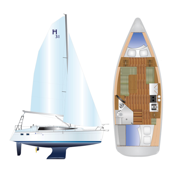
- Page 2 HUNTER OWNER’S MANUAL TABLE OF CONTENTS (CONT’D) PAGE DESCRIPTION OF MODEL Profile with Rig and Sail Dimensions…………………………….. Dimensions, Capacities, etc………………………………………. Deck Plan and Hardware………………………………………….. Deck Hardware Parts Listing……………………………………… Accommodation Plan………………………………………………. 40A-40C Dinette Table Operation……………………………………………...
- Page 3 HUNTER OWNER’S MANUAL TABLE OF CONTENTS (CONT’D) EQUIPMENT MANUALS AND INFORMATION Engine Manual Knotmeter and Depthsouder VHF Radio (except where not provided) Compass Information Stereo Manual Furling System Manual Marine Rigging Guide Winch Maintenance Guide ...
-
Page 4: Owner Information Card
Congratulations on your new sailing yacht manufactured craft; equipment supplied or fitted, systems, and informa- by Hunter Marine. We have engineered and constructed tion on operation and maintenance. Please read it care- your boat to be as fine a yacht as any afloat. In order to fully, and familiarize yourself with the craft before using it. - Page 5 Hunter are not covered by this limited warranty. The obligation of Hunter under this limited warranty is limited to the repair or replacement of hulls that it determines to be structurally defective. This is your sole and exclusive remedy.
- Page 6 Paint, window glass, Gelcoat, upholstery damage, plastic finishes, engines, engine parts, bilge pumps, stoves, blowers, pressure water pumps, propellers, shafts, rudders, controls, instruments, keels and equipment not manufactured by HUNTER. Any warranty made by the manufacturer of such items will be, if possible, given on to the first use purchaser.
-
Page 7: Warranty Registration Form
All repairs and/or replacements will be made by an authorized Hunter dealer, or at the option of Hunter, at the Hunter plant. If the repairs are of such a nature that the warranty work must be performed at the HUNTER plant, transportation costs to and from the HUNTER plant shall be paid by the owner. The la- bor cost reimbursement will be based on a Labor Allowance Schedule established by HUNTER and where not applicable, on a reasonable number of hours as determined by HUNTER. - Page 8 Dear Mr. Smith, Thank you for providing written notice of transfer of ownership. We are pleased you have se- lected a Hunter sailboat and we will make every effort to assure Hunter ownership will be a satisfying experience for you.
- Page 9 9) Warranty claims must be sent in duplicate and must contain the complete hull number and a brief description of work performed. Labor, parts, materials, and haul-outs must be listed separately. Claims for warranty must be sent to Hunter Marine not more than thirty (30) days after completion of work, or they may not be honored. PAGE 2E...
- Page 10 Marine, Mainship Motor Yachts, and Champlain. Luhrs Fishing Boats with its Alura divi- sion, as well as Hunter Marine, which The sea skiff is a class of boat that has exclusively manufactures sailboats. been very popular, owing to its seawor- thiness.
- Page 11 GLOSSARY OF SAILING TERMS Bend: 1, to secure a sail to a spar Chine: the line where the bottom of before hoisting; 2, to moor a boat; 3, the hull meets the side at an angle. Aback: describes a sail when the wind a sleeping place on board.
- Page 12 GLOSSARY OF SAILING TERMS Guard rail: a metal rail fitted around Kicking strap: a line used to pull the (rate UK); 3, UK: the distance a boat is carried by a current in a given time. the boat to prevent the crew falling boom down, to keep it horizontal, par- Drogue: a sea anchor put over the overboard.
- Page 13 GLOSSARY OF SAILING TERMS Member: a part of the skeleton of the Position line/ Line of position: a line used in the setting and trimming of hull, such as a stringer laminated into drawn on a chart, as a result of taking sails.
- Page 14 GLOSSARY OF SAILING TERMS Stall: a sail stalls when the airflow Terminal fitting: fitting at the end of a Waterline length (WL): the length of wire rope by which a shroud or stay a boat from stem to stern at the water- over it breaks up, causing the boat to can be attached to the mast, a tang or line.
- Page 15 EXPLANATION OF SAFETY PRECAUTIONS This manual contains safety precautions that must be observed when operating or servicing your boat. Review and understand these instructions. Denotes an extreme intrinsic hazard exists which would result in high probability of death or irreparable injury if proper precautions are not taken Denotes a hazard exists which can result in injury or death if proper precautions are not taken...
-
Page 16: Safe Boating Tips
SAFE BOATINGTIPS BE PREPARED Take a safe boating course. In the U.S., contact your local Boating Industry for de- tails. As the owner of the craft, obtain- Carry all safety equipment required by the ing and maintaining necessary laws that apply to your area. Require- safety equipment is your responsi- ments are generally available from the bility. - Page 17 SAFE BOATINGTIPS FLARES Most boats operating on coastal waters are required to carry approved visual distress signals, therefore check with FIRE/EXPLOSION HAZARD; Pyro- your local authorities as to which types technic signaling devices can cause are required. injury and property damage if not handled properly.
-
Page 18: Float Plan
PRE-DEPARTURE CHECKLIST Check bilge for extra water Check weather conditions and tides Check food supply Foul weather gear Linen, sleeping bags Fuel Water Sunscreens and sunglasses Tools Docking and anchor gear ... - Page 19 FLOAT PLAN 1. Name of person reporting and telephone number: 2. Description of boat NAME TYPE MAKE LENGTH REGISTRATION# HULL COLOR STRIPE COLOR DECK COLOR OTHER DISTINGUISHING MARKS 3. Number of Persons aboard NAME PHONE # ADDRESS NAME PHONE # ADDRESS NAME PHONE #...
-
Page 20: After Sailing Check List
AFTER SAILING CHECKLIST When leaving your Hunter at the dock will help protect the various parts of your for more than a short time, it is a good boat and add considerably to their at- idea to review the following checklist to tractiveness and usable life. - Page 21 ANCHORING Your Hunter comes with an on deck an- mean low tide depths and other local chor well and a Danforth type anchor as conditions when anchoring, as well as standard equipment.
-
Page 22: Diesel Engine
SAFE BOATING TIPS DIESEL ENGINE An engine owner's manual is supplied with your boat and should be read thor- oughly. It contains technical specifica- EXTREME HAZARD: carbon monoxide tions, running instructions and a mainte- gas (CO) is colorless, odorless and ex- nance schedule on lubricants and fluids. -
Page 23: Electrical System
This way, it is possible to maneuver if the engine should not start. ELECTRICAL SYSTEM Your Hunter is fitted with an electrical sys- tem designed for both AC and DC. While in port, you can operate any tool, appli-... - Page 24 SAFE BOATING TIPS ELECTRICAL SYSTEM (continued) To minimize shock hazard, connect and When leaving port, disconnect the dock- disconnect cable as follows: side power cord and turn the main DC breaker on. This allows you to use the 1. Turn off the boat’s shore power con- ship’s lights and other equipment de- nection before connecting or discon- signed to operate on direct current.
- Page 25 SAFE BOATING TIPS ELECTRICAL SYSTEM (continued) Hunter Marine recommends that on all the boat if it is unattended). Completely boats with either/both a house and start depleting a batteries internal charge can drastically shorten its life span. This in- battery, the cables be disconnected dur- ing winter storage or any time the boat cludes gel cell and glass mat batteries.
-
Page 26: Toilet Opening Hull Ports
SAFE BOATING TIPS TOILET There is a possibility of being fined for IMPORTANT: When not in use, lever must be left in the “dry” position to prevent having an operable direct overboard dis- flooding. charge of waste in some waters. Remov- ing seacock handle, in closed position, or Before using, place the lever in the “wet”... -
Page 27: Waste Discharge
Run pump only as long as necessary to remove water. Dry running can damage the pump motor WASTE DISCHARGE The Hunter is equipped with a head main electrical panel. Familiarize your- waste holding tank, hose lines, and thur- self with the locations of the deck pump... -
Page 28: Environmental Considerations
ENVIRONMENTAL CONSIDERATIONS FUEL AND OIL SPILLAGE The spilling of fuel or oil into our water- ways contaminates the environment and is dangerous to wildlife. Never discharge EXPLOSION/FIRE/POLLUTION HAZ- or dispose of fuel or oil into the water. It ARD: is dangerous and unlawful. Two com- Fill fuel tank to less than rated capacity. - Page 29 (gloves, safety glasses,respiration,etc) If an epoxy barrier coat is applied to a Hunter vessel, it must be registered with the Warranty Department prior to application of the product. If the dealer ap- plies bottom paint only, sanding will not be allowed and the no sanding system must be used.
-
Page 30: Stuffing Box
ENGINE, TRANSMISSION & DRIVETRAIN ENGINE Follow the fuel and lubrication requirements 2. Establish the shaft in the center of the in the Engine Manual. Check the engine oil shaft log by raising the shaft until it touches the top of the log – note position – lower the level before and after operation and use a shaft until it touches the bottom of the log –... -
Page 32: Steering Systems
MAINTENANCE COMPASSES A boat compass rarely exists in an envi- If you must depend solely on your com- ronment that is completely free from pass for navigation, make a quick check magnetic materials or influences. for any objects near the compass that may cause additional, unmeasured de- The compass on your boat should be viation. -
Page 33: Plumbing Systems
MAINTENANCE PLUMBING SYSTEMS All pumps should be checked frequently tems by walking through the boat with to insure proper operation. This is an the diagrams provided in this manual. It especially important regular mainte- is especially important that the owner nance item since proper functioning of a knows all the thru-hull valve locations pump could save your vessel from seri-... -
Page 34: Sail Care
MAINTENANCE CLEANING FIBERGLASS SURFACES Fiberglass surfaces should be cleaned It is a good idea to wax the fiberglass regularly. Normal accumulations of sur- once or twice a year to maintain a deep, face dirt can be removed simply by oc- glossy appearance. -
Page 35: Fabric Care
VINYL CARE These patterns, like all upholstery fabrics those recommended may result in irrepara- and vinyl, require a regularly scheduled ble damage to the product. cleaning program. A thorough cleaning In order for the above listed cleaning solu- should be administered on a daily, weekly or tions to work effectively on stubborn stains, monthly basis depending on use and expo- please allow time for the cleaning solution to... -
Page 36: Electrolysis And Galvanic Protection
ELECTROLYSIS AND GALVANIC PROTECTION Salt water allows electric current to flow from friendly association with metal components anodic to cathodic material. For any two on it. An easy place to fit an anode is on the metals from two components, their relative propeller shaft, or covering the propeller nut. - Page 37 INTERIOR FURNITURE & BULKHEAD SPRAY FINISH TEAK CARE manufactured by “Chemcraft International Teak wood is a high quality, extremely dura- ble wood with a high oil content. In order to Inc”. This material will seal and protect the help you protect the original beauty of your wood from moisture and weathering.
-
Page 38: Storage/Winterization
A second method is to disconnect raw water pickup hose from the raw the hoses at the pump, allowing water pump and immerse one end into a 5-gallon (19L) bucket of anti- freeze solution. Start engine and run PAGE 31... - Page 39 STORAGE/WINTERIZATION until antifreeze solution comes out charge battery near any open exhaust stack or until bucket is flame or a confined area. empty. Attach the raw water pickup CAUTION: Wear safety goggles and rubber gloves to protect your hose to the raw water pump. Tighten all clamps.
- Page 40 STORAGE/WINTERIZATION engine oil into the intake pipe or Primary choices for this list are items manifold while engine is turning. relating to the safety and security of DO NOT USE the starter to turn en- the unattended craft: turning off fuel gine or serious engine damage may valves, properly setting electrical result.
- Page 41 CE CERTIFIED Your Hunter has been manufactured in the United States and has been certified by the IMCI to be in compliance with the relevant parts of the Recreational Craft Directive 94/25/EC from the European Parliament. The CE mark means your craft meets or ex- ceeds all current International Organization for Standardization (ISO) standards and di- rectives in effect at time of manufacture.
-
Page 45: Dimensions, Capacities, Etc
31 DIMENSIONS, CAPACITIES, ETC. HULL LENGTH 29' 11 3/4" 9.13 m. LENGTH OVERALL (INCUDES BOW ROLLER) 30' 4 3/4" 9.26m. LENGTH OF WATERLINE (LWL) 28' 01" 8.55 m. BEAM (MAX)(without rubrail) 10' 8 3/4" 3.27 m. BEAM (MAX)(with rubrail) 11' 0 3/4"... -
Page 47: Deck Hardware List
31 DECK HARDWARE LIST ITEM QTY. DESCRIPTION COMPWAY U CHANNEL DECK RAIL SLIDER STBD DECK RAIL SLIDER PORT HELMSEAT MOUNT BRACKET HELMSMAN SEAT SEAHOOD SLIDER ARCH FIXED PORTLIGHT PORT FIXED PORTLIGHT STBD STERNRAIL PORT STERNRAIL STBD OPTIONAL WINDLASS ANCHOR ROLLER... - Page 66 H31 B&R RIG DESCRIPTION The B&R rig, utilized on the Hunter 31, rigging (like backstay adjusters). This eliminates the need for a backstay to design should prove more reliable than allow for a more efficient mainsail a rig with adjustable backstays or run- shape.
-
Page 71: Standing Rigging
HUNTER 31 CONVENTIONAL STANDING RIGGING ITEM WIRE SIZE FITTINGS OVERALL LENGTH 10ft 8 3/4" 3270 mm 1/4" 6mm T-TERMINAL 308-324 FORK 308-417 10ft 6" 3200 mm 1/4" 6mm EYE 308-362 EYE 308-362 10ft 10 1/8" 3305 mm 3/16" 5mm Stemball 308-510-01... - Page 72 HUNTER 31 FURLING STANDING RIGGING ITEM WIRE SIZE FITTINGS OVERALL LENGTH 10ft 7 7/8" 3250 mm 1/4" 6 mm T-TERMINAL 308-324 FORK 308-417 10ft 6 3/4" 3220 mm 1/4" 6 mm EYE 308-362 EYE 308-362 10ft 1/2" 3060 mm 5/32"...
- Page 74 On the Hunter 31 it is necessary to go do much to flatten the sail as in a up the mast in a bosun’s chair to tighten standard rig.
- Page 75 TUNING THE H31 B&R RIG the mast and see if it is straight (rather do. Keep in mind it is also possible to than bent from side to side). If not then have something too tight such as a adjust the lowers (D1) until it is. diagonal shroud.
- Page 95 NOTE TO CONSUMER THE FOLLOWING PAGES PROVIDE DETAILED INFORMATION, SCHEMATICS ETC. PERTAINING TO THE H31 STANDARD ELECTRICAL SYSTEMS AS WELL AS THE OPTIONAL ELECTRICAL SYSTEMS. READ THE DRAWING TITLE IN THE TITLE BLOCK TO BE SURE YOU ARE REFERRING TO THE CORRECT SYSTEM FOR YOUR MODEL.
- Page 99 12 V.D.C. DISTRIBUTION PANEL BREAKER DESCRIPTION PANEL LIGHTS ILLUMINATES BOTH A.C. & D.C. SIDES OF THIS PANEL FOR NIGHT USE CABIN LIGHTS SUPPLIES POWER TO ALL INTERIOR LIGHTS AND COCKPIT LIGHT L. P. GAS SUPPLIES POWER TO L.P. GAS SWITCH AT GALLEY. SEE "L.P. GAS MANUAL" FOR OPER. & SAFETY INST. REFRIGERATOR SUPPLIES POWER TO REF.
- Page 100 120V.A.C. DISTRIBUTION PANEL (230 OVERSEAS MODELS) BREAKERS DESCRIPTION "LINE 1" SIDE OF A.C. PANEL A.C. MAIN PROVIDES A.C. VOLTAGE TO THIS SIDE OF PANEL WHEN SHORE POWER CORD #1 IS CONNECTED TO OUTLET AT DOCKSIDE POWER SUPPLY. OUTLETS PROVIDES A.C. POWER TO THE BOAT'S OUTLETS. MICROWAVE SUPPLIES POWER TO OUTLET BEHIND MICRO.
- Page 129 MASTER ELECTRICAL AMPERAGE DATA 12V.D.C. SYSTEM CIRCUIT/BREAKER AMPERAGE D.C. MAIN 50amp PANEL LIGHTS 5amp CABIN LIGHTS 20amp COURTESY LIGHTS 10amp TANK INDICATOR 5amp WATER PRESSURE 10amp SHOWER SUMP 10amp MACERATOR 20amp FREEZER 15amp STEREO 10amp TV/DVD 10amp REFRIGERATION 15amp L.P. GAS 5amp WINDLASS (SWITCH) 5amp...
- Page 130 MASTER ELECTRICAL WIRING/CABLE DATA DESCRIPTION WIRE SIZE WIRE COLOR LPG SWITCH/POWER 16 gauge ORANGE/RED TANK DISPLAY 16 gauge RED/ORANGE FUEL SENDER 16 gauge PINK,ORANGE/WHITE NEGATIVE 16 gauge YELLOW FWD WATER SENDER 16 gauge ORANGE/BLUE, PINK/BLACK NEGATIVE 16 gauge YELLOW WATER PUMP 12 gauge BROWN NEGATIVE...
- Page 131 120V.A.C. SYSTEM TROUBLESHOOTING GUIDE (230V. OVERSEAS MODELS) COMPONENT SYMPTOM POSSIBLE SOLUTION/S SHORE POWER NO POWER TO PANEL SEE "POWER SYSTEM OPERATIONS" PAGE 63A-2 CHECK DOCKSIDE BREAKER AND/OR BREAKER #1 LOCATED IN AFT CABIN OR COCKPIT LOCKER. CHECK "RESETS" ON (OPT.)INVERTER (SEE "INVERTER MAN.") OUTLETS NO POWER SEE "POWER SYSTEM OPERATIONS"...
- Page 132 12V.D.C. SYSTEM TROUBLESHOOTING GUIDE TO POWER D.C. PANEL: TURN ON "D.C. MAIN" BREAKER ON BATTERY SWITCH PANEL, IT IS NOT NECESSARY TO TURN THIS IS TO POWER PANEL ON THE HOUSE BATTERY SWITCH TO THE "ON" POSITION TO SUPPLY POWER TO D.C. PANEL FOR CHARGING, SEE IF NO POWER TO PANEL: CHECK BATTERY CONNECTIONS IF NECESSARY.
- Page 133 SYSTEM TROUBLESHOOTING GUIDE CONT: COMPONENT SYMPTOM POSSIBLE SOLUTION/S WINDLASS UP/DOWN CONTROLS DON'T OPERATE SEE "TO POWER PANEL" PREV. PAGE WINDLASS WINDLASS SWITCH AT WINDLASS RESET PANEL ON? IS RESET TRIPPED? INSTRUMENTS REPEATERS DON'T OPERATE SEE "TO POWER PANEL" PREV. PAGE DO TRANSDUCERS NEED CLEANING? SEE INSTRUMENTS MANUAL VHF RADIO...
-
Page 138: Waste System
INDEX AIR CONDITIONING SYSTEM 63B-1 THRU 63 B-4 ANCHORING ARCH INSTALLATION AUTOPILOT (LAYOUT) BILGE PUMP (SCHEMATIC FOR ELECTRIC PUMP) 59B,59C BILGE PUMPS (LAYOUT) BOOM DECK HARDWARE 38,39,42A-1,42A-2 DIMENSIONS, CAPACITIES, ETC ELECTRICAL PANELS (NAV STATION DESCRIPTIONS) 63A-7 ELECTRICAL PANELS (SCHEMATICS) 63A-8,63A-9,64A ELECTRICAL SYSTEM 63A-1 THRU 65B-4 ELECTRICAL SYSTEM TABLE OF CONTENTS...
Need help?
Do you have a question about the 31 and is the answer not in the manual?
Questions and answers
Is the fiberglass overhead over the salon a single sheet or is it a two layer ehere water can run through on a 31 ft. 1985 Hunter?
What is the GRT of a 1987 Hunter 31