
Related Manuals for Alpha CFR 5000


Summary of Contents for Alpha CFR 5000
- Page 1 5000 & 5000RM Uninterruptible Power Supplies From Alpha Technologies ! ! ! ! ! Operator’s Manual...
- Page 2 ! ! ! ! ! Operator’s Manual ! ! ! ! ! CFR 5000 & CFR 5000RM Uninterruptible Power Supplies Alpha Technologies...
- Page 3 CAUTION Risk Of Electrical Shock To reduce the risk of electrical shock and to ensure the safe operation of the CFR 5000 and CFR 5000RM, these symbols are used throughout this manual. Where they appear only quali- fied personnel should carry out the instructions.
-
Page 4: Safety Checklists
DANGER: Sealed lead-acid batteries with high energy and chemical hazards are used. This manual contains important operation and safety instructions. Only qualified personnel should service the CFR 5000 and CFR 5000RM. CFR 5000 and CFR 5000RM Safety Checklist Carefully unpack the unit. Report any shipping damage at once. - Page 5 CFR 5000 & CFR 5000RM Safety Checklists (Continued) There are dangerous voltages inside the unit. Only qualified personnel should perform installation and maintenance. Live battery wires must not touch the unit’s chassis or any other metal objects. This can cause a fire or explosion.
-
Page 6: Table Of Contents
4.1 Setting Up RS–232 Communications ..1.2 Unpacking and Inspection Checklist ..4.2 Using the Opening Menu ......1.3 The Alpha CFR 5000 and CFR 5000RM ..4.3 Menu Tree ..........4.4 System, Input, Output & Battery Param- 2. Installation eters ............ -
Page 7: Introduction
Section 1 Introduction This section introduces you to the CFR 5000 and CFR 5000RM UPS’s: • The CFR series many advantages (Section 1.1). • An unpacking and inspection checklist (Section 1.2). • An tour of the units, their connectors, switches and control panels (Section 1.3). -
Page 8: The Cfr Advantage
The RS–232 communications port is SNMP and modem compatible. Safety Alpha designed the CFR to meet or exceed UL, CSA or VDE safety standards. This commit- ment to safety makes Alpha Technologies a leader in the power industry. Alpha Technologies... -
Page 9: Unpacking And Inspection Checklist
1 Introduction Unpacking and Inspection Checklist TIP: If items are missing or damaged, contact Alpha and the shipping company at once. Most shippers have a short claim period. Carefully remove the unit from its shipping container. Inspect it for damage and make sure the following items are included: One CFR series UPS. - Page 10 Country __________________________________ Telephone # _______________________________ Fax # ____________________________________ E Mail ___________________________________ For technical support contact Alpha Technologies customer service department directly at: i l a For emergency technical support 7 days a week / 24 hours a day call: USA: 1–800–863–3364 CANADA: 1–800–667–8743...
-
Page 11: The Alpha Cfr 5000 And Cfr 5000Rm
1 Introduction The Alpha CFR 5000 and CFR 5000RM TIP: Unless otherwise shown in this manual, the CFR 5000 and CFR 5000RM are identical and work the same way. The major difference is the CFR 5000RM does not have internal batteries. An Alpha External Battery Pack (EBP) must be connected (Section 2.4). -
Page 12: Display Panel
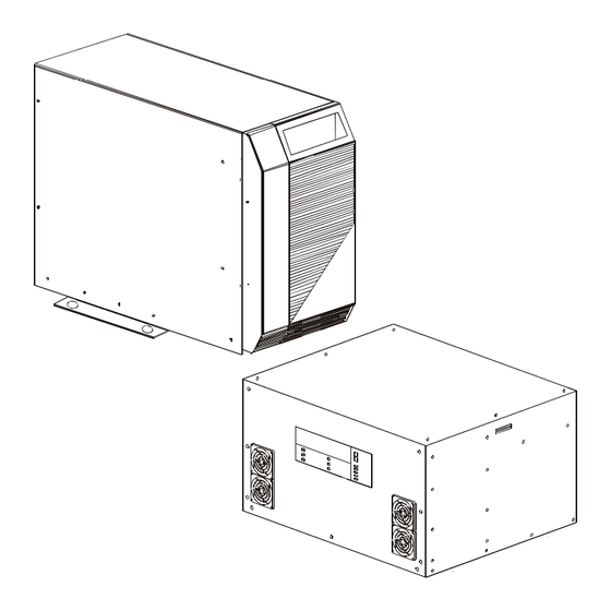
1 Introduction The Alpha CFR 5000 and CFR 5000RM (Continued) Feet The Alpha CFR 5000 and 5000RM (Continued) If you don’t secure the unit with the seismic brackets, you can stop the unit from moving by screwing these down. CFR 5000 Rack Mount (RM) Display Panel This is either the Standard Interface Display (SID) (Section 3.5) or the optional... - Page 13 1 Introduction The Alpha CFR 5000 and CFR 5000RM (Continued) 1.3.2 Rear Panel CFR 5000 CFR 5000RM Figure 1.1 Rear Panels Fans These fans cool the unit. They must not be blocked. Output Connector These plates are the unit’s output power con- nector.
-
Page 14: Battery Circuit Breaker
1 Introduction The Alpha CFR 5000 and CFR 5000RM (Continued) Input Line Cord or Terminal Block This is the unit’s line connector. It can either be a standard, grounded line cord or be factory configured to your specifications. Input Circuit Breaker This provides protection for the unit. - Page 15 An external IID plugs into this connector for remote control and monitoring. External Alarm Connector This RJ–45 connector allows the connection of an external alarm panel or an emergency shutdown switch (Section 2.5). Phone This connector is not used in the CFR 5000. Alpha Technologies...
-
Page 16: Installation
Section 2 Installation This section shows you how to install and connect the CFR 5000 and CFR 5000RM UPS’s: • A pre-installation checklist (Section 2.1). • How to unpack and install the unit (Section 2.2). • How to connect the unit to the loads and the line (Section 2.3). -
Page 17: Pre-Installation Checklist
• 230 VAC units: the voltage must be between 207 VAC and 242 VAC. • 208 VAC units: the voltage must be between 188 VAC and 216 VAC. • 120 VAC units: the voltage must be between 110 VAC and 125 VAC. Also see Section 2.8, “Transformer Output Load Sharing.” Alpha Technologies... - Page 18 Before installation see that the generator’s output voltage meets the unit’s input voltage requirements as shown on both nameplates. A 240 VAC unit must be attached to a 240 VAC generator. Alpha Technologies...
-
Page 19: Installing The Unit
2 Installation Installing the Unit 2.2.1: CFR 5000 TIP: The seismic brackets can be removed if they are not required by the local code or you are not in an earthquake zone (See Tools and Materials Required: • Fork lift or other means of transporting heavy objects (up to 381 lbs./173kg). - Page 20 Remove the bracket by unscrewing the 3 phillips screws attaching the bracket to the chassis. Reattach the cover and the front panel. To stop the unit from moving, screw down the feet until they are solid against the floor. Installation finished Alpha Technologies...
- Page 21 Unscrew the box attached to the pallet. Move the unit to the rack. Mount it in the rack. The mounting screws are not provided by Alpha. Use the screws speci- fied for your rack. Mount an Alpha external battery pack (Section 2.4).
-
Page 22: Connecting The Unit
• If it passes go to the next step. • If it doesn’t do troubleshooting (Sections 3.4, 5.2). Turn off the unit (Section 3.2). Connect the loads. The loads must be turned off before connection. Connection Finished Figure 2.1 Connecting the Unit (Plug and Connector) Alpha Technologies... - Page 23 • If it doesn’t do troubleshooting (Sections 3.4, 5.2). Switch off the unit (Section 3.2). Connect the loads to the terminal block as shown in Figure 2.4. See for the recom- mended wire gauges and torques. Connection Finished Alpha Technologies...
- Page 24 N t o N t o N N N N N L L L L L * Caution: Refer to the voltage and frequency ratings for the unit as shown on the nameplate. Figure 2.4 Output Terminal Block Wiring Alpha Technologies...
-
Page 25: Connecting The External Battery Pack
Verify the battery circuit breaker is switched off. Keep it off until after the unit has been started with line power. For the CFR 5000, loosen the cover plate and slide it up to expose the connector (Figure 2.6) . - Page 26 2 Installation 2.4 Connecting the External Battery Pack (Continued) Figure 2.5 Connecting an External Battery Pack to the 5000RM Figure 2.6 Connecting an External Battery Pack to the 5000 Alpha Technologies...
-
Page 27: Connecting The External Alarm Port
N.O. Low Failure Battery Warning N.C. Battery OK N.C. Line RJ-45 Present Circuit Connector (8-Pin Type) UPS Internal UPS External Contact Rating: 30 VDC @ 1 Amp Optional N.O. EPO Switch Figure 2.7 Wiring the External Alarm Port Alpha Technologies... -
Page 28: Connecting The Rs-232 Port
1) The cable must be less than 50 ft (15m) long and it must be shielded to meet EMI requirements. 2) The RS–232 is not isolated. Signal ground is directly connected to the internal logic ground. Contact Alpha if the external battery connector must be referenced to positive ground instead of negative ground (the factory default). TXD 2... -
Page 29: Connecting The Lan Port
Common Line Battery Connected Fail Connected Connected Output +12 VDC 5 mA (Max) Shutdown N.O. Low N.O. Line Battery Failure +12 VDC Output Common 5 mA (Max) Shutdown UPS Internal UPS External Figure 2.9 Wiring the LAN Port Alpha Technologies... -
Page 30: Transformer Output Load Sharing
Since loads are shared between windings, you can exceed a winding’s output without exceed- ing the unit’s maximum current output. There are two ways to calculate the current drawn by the loads; measuring or displaying the output current. Alpha Technologies... - Page 31 120/120/240 VAC Current Measurement Points Output Current 2 208 VAC Winding 2 Not Used Receptacle 208 VAC Output Current 1 120 VAC Winding 1 Receptacle Output Current L1 Output Terminal Block Figure 2.13 120/208 VAC Current Measurement Points Alpha Technologies...
- Page 32 Use the menu to display Output Current 1 and Output Current 2. The current in Winding 1 (Output Current L1) is the sum of Output Currents 1 and 2. The current in Winding 2 is Output Current 2. Alpha Technologies...
-
Page 33: Operation
Section 3 Operation This section shows you how to operate the CFR 5000 and CFR 5000RM UPS’s: • How to turn the unit on and off (Sections 3.1, 3.2). • How to start the unit’s self test (Section 3.3). • How to troubleshoot the unit with the SID (Section 3.4). -
Page 34: Turning On The Unit
One at a time, turn on the loads. As each load is turned on, look at the load indicator on the control panel to make sure the unit is not overloaded (Section 3.5, “Output Load”). Start Up Finished Alpha Technologies... -
Page 35: Turning Off The Unit
Switch off the battery circuit breaker. Switch off the input circuit breaker. If the unit is to be serviced, switch off the main utility circuit breaker. DANGER: During servicing place a warning notice on the circuit breaker supplying the unit. Shutdown Finished Alpha Technologies... -
Page 36: Testing The Unit
If a fault is found, the unit defaults to Line SHUTDOW N TEST SERVICE Present operation without interrupting the output. The Service LED turns on. Do troubleshooting (Sections 3.4, 5.2). TIP: The unit cannot provide backup battery power when the Service LED is Self Test Finished Alpha Technologies... -
Page 37: Troubleshooting With The Sid
* After fixing the malfunction, these are cleared from the display panel by shutting down and restarting the unit. ** After fixing the malfunction, the unit automatically returns to Line Present mode, clearing the malfunction from the panel. Figure 3.1 Fault Chart Alpha Technologies... -
Page 38: Controlling The Unit With The Standard Interface Device (Sid)
Output Load LEDs turn on or flash (Section 3.4). Low Battery Warning This red LED turns on when the battery voltage is 8% below nominal. This shows the batteries are almost discharged and a shutdown is pending. You should start turning off the loads. Alpha Technologies... -
Page 39: Low Battery Shutdown
It can also be used as a self test. If the Line Present LED is on, press it for 5 seconds. This tests the inverter and batteries for one minute by providing backup battery power to the loads, returning to line present mode when done. Alpha Technologies... - Page 40 WARNING: Do not run the unit when it is overloaded. Damage to the unit, the inverter or the batteries can result. If the unit is in Output Voltage Shutdown mode the LED’s will continuously sequence until this mode is stopped (Section 4.5.2, “Sub Menu #50: Set Output Shutdown Param- eters”). Alpha Technologies...
-
Page 41: Communication
Section 4 Communication This section shows you how to control the CFR 5000 and CFR 5000RM UPS’s with RS–232 computer commands: • How to setup communications with Windows © HyperTerminal (Section 4.1). • How to understand and use the opening menu (Section 4.2). -
Page 42: Setting Up Rs-232 Communications
Connection Description screen appears (Figure 4.1). Enter a name and choose an icon for your unit. Click OK. Figure 4.1 Connection Description Screen The Connect To screen appears (Figure 4.2). Connect to COM 1. Click OK. Figure 4.2 Connect To Screen Alpha Technologies... - Page 43 (Figure 4.3). Fill out the fields as shown. Click OK. Figure 4.3 COM 1 Properties Screen The CFR Screen appears. Press Enter to go to the Opening ALPHA TECHNOLOGIES–CFR OPENING MENU Menu (Figure 4.4). 1 SYSTEM PARAMETERS 2 INPUT PARAMETERS The Opening Menu (Figure 4.5) 3 OUTPUT PARAMETERS appears.
-
Page 44: Using The Opening Menu
Enter and retype the command. • “Service2: Service Code 3” is displayed in the alarm field every time the unit starts. This is normal. To clear it, press Enter. ALPHA TECHNOLOGIES–CFR OPENING MENU 1 SYSTEM PARAMETERS 2 INPUT PARAMETERS... - Page 45 . t s t i u t i n y l l t i n t i u . f f Figure 4.7 Battery Alarms Alpha Technologies...
- Page 46 I . y l l f I . x i f t l u . t l t i n . t l l i a l i a i t c Figure 4.9 Environmental and Service Alarms Alpha Technologies...
-
Page 47: Menu Tree
75 Slow Detect High Ref press Enter. Power Factor 76 Slow Detect Hys. Lo Ref Line Frequency 77 Slow Detect Hyst Hi Ref 78 Max PLL Slew Rate 79 Battery Warning Ref 4 Battery Parameters Voltage Current Charger Status Temperature Alpha Technologies... -
Page 48: System, Input, Output & Battery Parameters
4.4.2 Main Menu #2: Input Parameters This displays selected input parameters. s t l n i l a t l n i l . t n s t t . t u n i l Figure 4.10 Input Parameters Menu Alpha Technologies... - Page 49 Output Voltage 2 120 VAC Output Voltage 1 Winding 1 Receptacle Output Current L1 Output TIP: Output Current L1= Terminal Block Output Current 1+Output Current 2 Figure 4.12 Output Voltage and Current Measurement Points (120/208/240 VAC, 60 Hz Units) Alpha Technologies...
- Page 50 . t n t i n t i n u l i n i l c i t l l a ° Figure 4.14 Battery Parameters Menu Alpha Technologies...
-
Page 51: User Parameters
. s t " " F Figure 4.15 User Parameters Menu Alpha Technologies... - Page 52 I . , t u Y " " . Y " " , t i n e t I " " , t i n s t i e t I Figure 4.16 Set Output Shutdown Parameters Menu Alpha Technologies...
- Page 53 0 " " 4 t i n u l i n i l f l a t i n c i t y l l e t I Figure 4.16 Set Output Shutdown Parameters Menu (Continued) Alpha Technologies...
- Page 54 " " ) o " " f f " r " . n i . t l Figure 4.17 Transmit Unsolicited Alarms Menu Alpha Technologies...
-
Page 55: Maintenance Parameters
Usually these factory settings never have to be changed. CAUTION: Improper settings can damage the unit. If you have any questions, con- tact Alpha Technologies before changing them. t i n i t i... -
Page 56: Installing And Using The External Modem
• One-time access to the CFR via a computer link. Settings: • RS–232 Speed: 1200 Baud between CFR and modem. • RS–232 Signals: Rx, Tx and Gnd. • Handshaking: None, neither hardware (RTS/CTS) nor software (XON/XOFF) are used. • Modem Speed: Same as the modem’s. Alpha Technologies... - Page 57 If you have more than one unit, set the “Location ID” (Item #526) to a unique, de- scriptive string (e.g. Rm 222). Set “Enable Automatic Alarms” (Item # 520) to YES. If you want remote dial-in access to the RS–232 menus, set “Enable Remote Ac- cess” (Item #521) to YES. Alpha Technologies...
- Page 58 2 2 2 2 2 6 6 6 6 6 . s t 3 3 3 3 3 7 7 7 7 7 4 4 4 4 4 8 8 8 8 8 Figure 4.21 Modem DIP Switch Settings Alpha Technologies...
- Page 59 AT command to control the auto answer mode (either “ATS0=1” or “ATS0=0”). For modems that do not support the extended Hayes commands, you should create an equivalent command. In most cases the simplified string: • ATQ0V1 works well. Alpha Technologies...
- Page 60 (Item #528) the CFR tells the modem to disconnect from the host. This stops a faulty host from tieing up the phone line and preventing other calls from being received or alarms from being sent out. Modem Installation Finished Alpha Technologies...
- Page 61 For most functions you will be asked for a password. The factory set password is 1111. If you change it, make sure a written copy is kept in a safe and accessible place. Continued on the next page. Alpha Technologies...
- Page 62 5 5 5 5 5 6 6 6 6 6 u f l f l e 7 7 7 7 7 f l e f l e e l i 8 8 8 8 8 Figure 4.22 External Modem Setup Menu Alpha Technologies...
- Page 63 & & & & . t s y l l . t i t l u . l l Figure 4.22 External Modem Setup Menu (Continued) Alpha Technologies...
-
Page 64: Maintenance
• How to measure the battery backup time (Section 5.1). • How to troubleshoot the unit (Section 5.2). • How to return the unit to Alpha for repair (Section 5.3). • How to replace the CFR 5000’s internal batteries (Section 5.4). -
Page 65: Testing The Battery Backup Time
The Low Battery Warning LED turns on. Record this time. The run time is the time between Turn on the Input circuit breaker. The unit runs on line power and the batter- ies start charging Battery Backup Time Test Finished Alpha Technologies... -
Page 66: Troubleshooting
If the unit fails to perform a specific function, Figure 5.1 lists typical symptoms, causes and solutions, starting with the most obvious and working systematically. If you cannot resolve a problem, contact Alpha’s customer service department. The unit’s electronics require no mainte- nance. - Page 67 . s t n i l i a f r u l a t l n i l , f f u l i , f f y t l Figure 5.1 Troubleshooting Table (Continued) Alpha Technologies...
-
Page 68: Returning The Cfr To Alpha For Repairs
USA: 1–800–863–3364 CANADA: 1–800–667–8743 5.4 Replacing the Internal Batteries (CFR 5000 Only) This procedure applies only to the tower version of the CFR 5000. The CFR 5000RM uses an external battery pack. DANGER: 1) Read the battery safety precautions in the front part of this manual before proceed- ing. - Page 69 Lift the cover upward and away from the chassis. Pull Out DANGER: Make sure the cover does not touch the batteries or any internal compo- nents. Panel and Cover Removal Finished. Go to Step 2. Alpha Technologies...
- Page 70 The voltage should be between 54 VDC to 57 VDC. • If it is, switch off the Input circuit breaker and disconnect the utility line. • If it is not, the charger is faulty. Contact Alpha Technologies customer service de- partment.
- Page 71 WARNING: Always remove the copper straps first and attach them last to reduce the chance of sparking. Disconnect: 1) The copper straps. 2) The battery connection wires. 3) The in-line fuse. In-Line Fuse Remove Copper Straps FIRST Attach them LAST Black Battery Connection Wires Red Battery Connection Wire Alpha Technologies...
- Page 72 Battery Retaining Bars Battery Retaining Bars Reinstall the battery retaining bars Rewire the batteries. Reattach the cover, the front panel, the loads and the line. Restart and test the unit as given in Section 3.1. Battery Replacement Finished Alpha Technologies...
-
Page 73: Configuring The Input/Output Voltage
• If reconfiguring from 208/240 VAC to 120 VAC, the 30 Amp input circuit breaker must be replaced with a 50 Amp circuit breaker. Contact Alpha Technologies and ask for Alpha part number 470–102–10. It is available from Carlingswitch (part # BB2–B0–26–... - Page 74 120/208/240 VAC. Configure it to the input voltage you are using. 208 V 120 V INPUT INPUT LOWER TERMINALS INPUT CONFIGURATION WHITE CHART BLACK 240 V INPUT TRANSFORMER WHT/BLK INPUT TERMINAL BLK/WHT BLOCK BLK/RED Alpha Technologies...
- Page 75 Wire the output connector(s) to the output voltage you need. Reattach the cover and the front panel. Turn on the unit (Section 3.1). Before turning on the loads, measure the output voltage to make sure this procedure has been done correctly. Voltage Reconfiguration Finished Alpha Technologies...
- Page 76 700-255-xx Board Reconfigure the DIP switches and the jumpers according to the table printed on the main board (see the diagram in Section 5.5.1, Step 1). Main Board Reconfiguration Finished. Go to Step 2. Alpha Technologies...
- Page 77 If needed, configure the terminal block to the input voltage you are using as shown below. 208V 120V INPUT INPUT UPPER TERMINALS WHITE BLACK 240V WHT / BLK INPUT BLK / WHT BLK / RED Input Terminal Block Reconfiguration Finished. Go to Step 3. Alpha Technologies...
- Page 78 To Output To Output Receptacles Receptacles Reattach all of the unit’s panels. Turn on the unit (Section 3.1). Before turning on the loads, measure the output voltage to make sure this procedure has been done correctly. Voltage Reconfiguration Finished Alpha Technologies...
-
Page 79: Battery Run Times
- - - - - - - - - - - - - - - - - - - - - - - - - - - - - - - - - - - - - - - Alpha Technologies... -
Page 80: Specifications
NOTES: 1) Specifications subject to change without notice. 2) These specifications are based upon use with computer-type loads with a crest factor of 3:1 (Max) and a typical power factor of 0.75. Alpha Technologies... -
Page 81: Index
Adjusting Unit to Local Line Conditions ....49 CFR 5000, CFR 5000RM Alarms On Display Panel ....... 32–34 Alpha, Returning Unit to for Repair ...... 62 Alarms, RS-232 ..........39–40 Battery Backup Time, Measuring ......59 Alarm Off Button on SID Panel ......33 Battery Charger Test ........... - Page 82 Emergency Power Off Switch ........ 21 Inspection Checklist ..See Unpacking Checklist Emergency Shutdown Procedure ......Installation ............Inside Rear Cover Installation Checklist ........ii, 11 Installation .............13–15 Emergency Technical Support ......62 Inverter On/Off via RS–232 ........47 Environmental Requirements ......11–12 Alpha Technologies...
- Page 83 Rear Panel ............7–9 Menu Tree, RS–232 ..........41 Reconfiguring Input/Output Voltage ....67–72 Modem, External ..See RS–232 Communications Remote Monitoring With Also See RS–232 Communications Monitoring, Remote .... See Remote Monitoring External Alarm Panel .......... 21 Alpha Technologies...
- Page 84 Emergency Power Off Switch ......21 Present, Display Panel Shows ......32 How Unit Shows A Shutdown ......34 Wiring To ............16–18 Normal ............... 29 Output Shutdown via RS–232 ......46–47 User Parameters, RS–232 ......41, 45–48 Alpha Technologies...
- Page 85 Warranty ..............80 Windows HyperTerminal ................See RS–232 Communications Wiring Alarm Port ............21 Battery ..........19–20, 62–66 Checklist ........... ii, 11–12 External Battery Pack ........ ii, 19–20 Loads and Line ..........16–18 RS–232 Port ............22 Alpha Technologies...
-
Page 86: Warranty
Alpha Technologies warrants its equipment to be free of manufacturing defects in material and workmanship for a period of 24 months from the date of manufacture. The liability of Alpha Technologies under this warranty is solely limited to repairing, replacing, or issuing credit for such equipment (at the discretion of Alpha Technologies), provided that: 1. - Page 87 (mounted on wall) 2 Turn off the Input Circuit Breaker. For emergency technical support 7 days a week / 24 hours a day call: USA: 1–800–863–3364 CANADA: 1–800–667–8743 For technical information, contact Alpha Technologies customer service department directly at: i l a...
- Page 88 Units R5–R7, Regents Park Estate Cnr Park Rd. and Prince’s Rd East Regents Park, NSW 2143, Australia Tel: +61–2–9722–3320 Fax: +61–2–9722–3321 Alpha sales and service offices located throughout the world © 2004 Alpha Technologies http://www.alpha.com Printed In Canada 017–111–B0 01 / 04...
Need help?
Do you have a question about the CFR 5000 and is the answer not in the manual?
Questions and answers