
Related Manuals for Alpha XM2-300HP


Summary of Contents for Alpha XM2-300HP
- Page 1 XM2-300HP Technical Manual XM2-300HP XM2-300CE-HP Effective: September 2010 member of The Group ™...
- Page 2 Power ® Alpha Technologies...
- Page 3 Per FCC 47 CFR 15.105: This equipment when installed in an Alpha enclosure has been tested and found to comply with the limits for a Class B digital device, pursuant to part 15 of the FCC Rules. These limits are designed to provide reasonable protection against harmful interference in a residential installation.
-
Page 4: Table Of Contents
Safety Notes ........................7 Battery Safety Notes......................8 Utility Power Connection Notes ....................9 Grounding and Earth Connection Notes................11 Introduction to the XM2-300HP Power Supply ............12 Theory of Operation ..................13 1.1.1 AC (Line) Operation ................13 1.1.2 Standby Operation ................14 1.1.3 Charger Operation ................ - Page 5 4.1.2 Self Test Operation ................33 4.1.3 Standby Operation ................34 Using the Smart Display ................35 Smart Display modes for XM2-300HP ............37 4.3.1 Operation Normal ................37 4.3.2 Comms Information Display (with DPM) ........... 38 4.3.3 Setup Menu ..................39 4.3.4 Menu Structure and Navigation (from Operation Normal screen) ..
- Page 6 Fig. 4-7 Smart Display LEDs ......................... 47 Fig. 6-1 Emergency Shutdown ......................59 Table 4-1 AC Output ..........................33 Table 4-2 Major Alarms ..........................45 Table 4-3 Minor Alarms ..........................46 Table 7-1 XM2-300HP Power Supply Specifications ................60 017-877-B1-001 Rev. A...
-
Page 7: Safety Notes
Always use proper lifting techniques whenever handling units, modules or batteries. • The XM2-300HP Power Supply contains more than one live circuit! Even though AC voltage is not present at the input, voltage may still be present at the output. -
Page 8: Battery Safety Notes
The XM2-300HP has been investigated by regulatory authorities for use in various Alpha enclosures. If you are using a non-Alpha enclosure, it is your responsibility to ensure your combination conforms to your local regulatory requirements, and that the XM2-300HP power supply remains within its environmental specifications. -
Page 9: Utility Power Connection Notes
Equipped with a grounding clamp, on the enclosure, to facilitate dedicated grounding. NOTE: When bonding the box to a neutral plate is required, use the long green bonding screw provided (Alpha P/N 523-011-10, Square D P/N 40283-371-50). 017-877-B1-001 Rev. A... - Page 10 Typical 120Vac 20A Receptacle Wiring, 5-20R (Black) Neutral (White) Ground (Green) (P/N 531-006-10) NOTE: When bonding the box to a neutral plate is required, use the long green bonding screw provided (Alpha P/N 523-011-10, Square D P/N 40283-371-50). 017-877-B1-001 Rev. A...
-
Page 11: Grounding And Earth Connection Notes
As a minimum requirement for the protection of Alpha equipment, the local utility service must provide a low- impedance path for fault current return. In addition, there must be a low impedance bonded path between the Alpha Power Supply power plug Ground Pin and the Enclosure. -
Page 12: Introduction To The Xm2-300Hp Power Supply
In standby mode, the XM2-300HP powers the load until the battery voltage reaches a low-battery cutoff point. When utility power returns, the XM2-300HP transformer module waits a short time (approximately 20 to 40 seconds) for the utility voltage and frequency to stabilize and then initiates a smooth, in-phase transfer back to AC line power. -
Page 13: Theory Of Operation
Introduction to the XM2-300HP, continued Theory of Operation The modular XM2-300HP is composed of the: • Chassis, which contains a transformer and transfer isolation relay. • Inverter module, which is required for standby operations and contains circuitry needed for the three-stage temperature-compensated battery charger, DC to AC converter (inverter), AC line detectors and Smart Display. -
Page 14: Standby Operation
AC line to standby operation, the battery powered inverter comes online as the isolation relay switches to prevent AC power from back-feeding to the utility. The following changes also occur within the XM2-300HP: • The isolation relay opens to disconnect the AC line from the primary winding of the transformer. -
Page 15: Charger Operation
Theory of Operation, continued 1.1.3 Charger Operation The XM2-300HP uses a three-stage, temperature-compensated battery charger. During AC line operation, the inverter winding on the transformer feeds the charger circuit which provides BULK, ACCEPT and FLOAT charge voltages to the battery. -
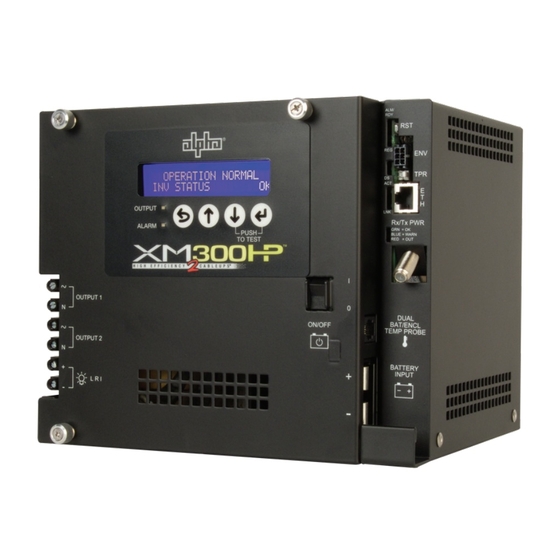
Page 16: Xm2-300Hp Layout
XM2-300HP Layout 1.2.1 Transformer Module Overview AC Output Circuit Protection: XM2-300HP power supplies use an 8A circuit breaker. To provide increased durability, an integrated sheet metal guard protects the line cord and circuit breaker. LRI (Local/Remote Indicator): The LRI lamp option is used in conjunction with the automatic performance feature and plugs directly into the LRI connector. -
Page 17: Inverter Module Overview
(BULK, ACCEPT, and FLOAT) charger. Smart Display: All operational functions, system testing, setup items, and alarms are available via the Smart Display panel on the front of the XM2-300HP (the Smart Display is covered in detail in Section 4.2). Display functions are accessible by pressing any of the four keys: ESCAPE, UP, DOWN or ENTER. -
Page 18: Fig. 1-7 Inverter Module Connections
Inverter Module Overview, continued Battery Switch: The battery switch disconnects the battery from the inverter module’s DC circuit. With the battery switch turned off, the XM2-300HP power supply does not transfer to standby mode, the inverter is disabled, and the battery charger cannot charge the battery. -
Page 19: Optional Status Monitoring Module
The XM2-300HP supports the Alpha Technologies DPM communication module. The module may be ordered factory-installed or as auser-installed field upgrade. NOTE: If communications options are installed, Alpha highly recommends adding a coaxial surge arrestor for the transponder (See Section 1.3, Optional Features). CAUTION! Handle these modules with extreme care. -
Page 20: Recommended Enclosure System Options
Using the programmable retry limit, the operator can select how many times (0-40) after a programmable delay (5-301 seconds) the PIM will attempt to reconnect an output that has been shut down. Once the limit is reached, the XM2-300HP automatically retries once every 30 minutes until the fault clears. -
Page 21: Installation
See the “CableUPS Quick Start Guide” (Alpha P/N 017-877-B0) that accompanies each power supply. SAVE THE ORIGINAL SHIPPING CONTAINER. Use the original shipping container if the XM2-300HP needs to be returned for service. If the original container is not available, make sure the unit is well packed with at least three inches of shock- absorbing material to prevent shipping damage. -
Page 22: Installation Procedure
XM2-300HP remains within its environmental specifications. CAUTION! The battery is an important part of the XM2-300HP. Properly install and test all batteries, battery connections and battery cables before you connect them to the power supply. Verify the Inverter Module’s battery switch is OFF. -
Page 23: Installing The Optional Ac Indicator (Aci) Lamp
WHITE housing (see Fig. 2-2). Connect the shorter BLACK/WHITE set of wires to the BLACK/WHITE wires leading from the SPI. The remaining set of longer wires connects to the Output 1 connector on the front of the XM2-300HP (Fig. 2-3). Enclosure Wall To SPI To Output Fig. -
Page 24: Fig. 2-3 Aci/Lri Connection
Installation, continued Installing the optional AC Indicator (ACI) Lamp, continued Installation is complete. Go to Start-up Test (Section 4.1, Start-up and Test). ATTENTION: See Section 5.6, Check Output Connection, for inspection guidelines. Fig. 2-3, ACI/LRI Connection 017-877-B1-001 Rev. A... -
Page 25: Inverter Module Removal And Installation
Installation, continued Inverter Module Removal and Installation The XM2-300HP power module comes with a field-replaceable inverter module assembly containing the inverter and control logic. The inverter module accepts optional communications modules to facilitate remote status monitoring. The removable module is located on the front of the XM2-300HP power supply. -
Page 26: Protective Interface Module Installation (Optional Feature)
You can use the programmable retry limit to select how many times (0-10) after a programmable delay (60-600 seconds) the PIM will attempt to reconnect an output once it has been shut down. When the limit is reached, the XM2-300HP power supply automatically retries once every 30 minutes until the fault clears. -
Page 27: Programming The Pim
Retry Delay: The time between each attempt to restart an output in the event of an overcurrent event. Retry Limit: The number of times the XM2-300HP will attempt to restart an output connection. Once the RETRY LIMIT is exceeded, the XM2-300HP will attempt to restart the output connection every 30 minutes. -
Page 28: The Setup Menu
Installation, continued Programming the PIM, continued 2.5.1 The Setup Menu Press the Enter key to access the Setup Menu. Use the Setup menu to view or change the programmable operating parameters of the power supply or the optional PIM. Navigation is similar to the Operation Normal menu. -
Page 29: Service Power Inserter (Spi)- Le
Service Power Inserter (SPI-LPE) To connect the coaxial cable Before you remove the cover, unplug the SPI-LPE from the XM2-300HP. Remove the two screws holding the cover to the SPI-LPE chassis. Remove the SPI-LPE cover to expose the circuit board and seizure screw assembly. - Page 30 Using the switch on the top of the SPI-LPE, turn the unit ON to select the standby XM2- 300HP as the power source to the cable plant. The switch should only be in the ALT position when the service XM2-300HP is connected to the cable. When in ALT, the standby XM2-300HP is bypassed for service or removal.
-
Page 31: Configuration
The input voltage on many models is factory set. Ensure proper name plate rating prior to installation. 3.2 AC Output Voltage Reconfiguration The output voltage of the XM2-300HP can be reconfigured by moving the Output Tap jumper per the procedure below. NOTE: XM2-300HP CE models have only a 63Vac output and are not reconfigurable. -
Page 32: Operation
Verify the AC circuit breaker (on the customer supplied service disconnect) and the battery switch on the XM2-300HP are off. Plug the XM2-300HP power cord into the convenience outlet and connect the battery cable to the CableUPS. Plug the RTS into the temp probe connection and attach it to the negative terminal of the battery. -
Page 33: Self Test Operation
4.1.1 AC Line Operation, continued Use the Smart Display to verify XM2-300HP operations. If desired, the No Battery alarm can be disabled by changing Battery Capacity to “0” in the setup menu. Use the Smart Display to verify AC output (±5%). -
Page 34: Standby Operation
Momentarily fail the AC utility input power by switching the AC (service disconnect) circuit breaker to OFF. The XM2-300HP starts operating in the inverter mode. Use the Smart Display or a true RMS voltmeter to verify output. Output voltages should appear within ±5% of: 87Vac for 90V units, 63Vac for CE units, and 60Vac for 60V units at nominal line input voltage. -
Page 35: Using The Smart Display
Using the Smart Display All operational functions, system testing, setup menus, and alarms are available via the illuminated display panel on the front of the XM2-300HP. Display functions are accessible by pressing any of the four keys: ESCAPE, UP, DOWN, and ENTER. -
Page 36: Fig. 4-3 Smart Display Panel
Operation, continued Using the Smart Display, continued Display Backlighting The display is normally unlit. Press any key once to activate backlighting and illuminate the display without deactivating Auto Scroll. Auto Scroll The display is normally in Auto Scroll mode, continually cycling through the sub-menu items at a two-second interval. -
Page 37: Smart Display Modes For Xm2-300Hp
Smart Display modes for XM2-300HP 4.3.1 Operation Normal If no alarms are present, the XM2-300HP power supply operates in Operation Normal display mode. In this mode you can view the primary operating parameters of the power supply while the display auto scrolls through the available menu items at two-second intervals. -
Page 38: Comms Information Display (With Dpm)
Operation, continued Smart Display modes for XM2-300HP, continued 4.3.2 Comms Information Display (with DPM) Pressing ENTER while in the Operation Normal screen will open the Comms Information display (only displayed when paired with DPM, otherwise display will read “NO DATA”). This mode operates in a similar fashion as the Operation Normal display. -
Page 39: Setup Menu
Operation, continued Smart Display modes for XM2-300HP, continued 4.3.3 Setup Menu Pressing ENTER while in the Comms Status display opens the Setup Menu, one level below the Comms Status display. Using the Setup menu you can view and change the programmable operating parameters of the power supply or the optional PIM. - Page 40 Operation, continued Smart Display modes for XM2-300HP, continued 4.3.3 Setup Menu, continued The Setup Menu contains the following items: Top Line (provides additional information) • SET UP MENU • TO MANUAL SCROLL • <ESC> TO COMMS INFO Second Line (cycles through the following parameters):...
-
Page 41: Fig. 4-6 Setup Menu Display
Operation, continued Smart Display modes for XM2-300HP, continued 4.3.3 Setup Menu, continued SETUP MENU CODE VER 7.01.0 DEVICE ADDRESS ALPHACELL OTHER FLOAT V/C 2.27 ACCEPT V/C 2.40 TEMP COMP BATT CAPACITy 100Ah # BATT STRINGS* BATT 1 DATE M/y* 01/10... -
Page 42: Menu Structure And Navigation (From Operation Normal Screen)
Operation, continued Smart Display modes for XM2-300HP, continued 4.3.4 Menu Structure and Navigation (from Operation Normal screen) OPERATION NORMAL (Single-step information) OPER MODE = LINE BATT STATUS INV STATUS DPM STATUS INPUT VOLTAGE 120V INPUT FREQUENCY 60Hz* INPUT CURRENT INPUT WATTS... -
Page 43: Menu Structure And Navigation (From Active Alarms Screen)
Operation, continued Smart Display modes for XM2-300HP, continued 4.3.5 Menu Structure and Navigation (from Active Alarms screen) OPERATION NORMAL ***ACTIVE ALARMS*** OPERATION NORMAL (Single-step Information) Auto-Scroll Information (Auto-scroll Information) (Auto-scroll Information) OPER MODE = LINE Self Test Fail OPER MODE = LINE... -
Page 44: Alarm Indications
UP or DOWN. Press DOWN to scroll through the list of remedies. Alarms are classified in two categories: MAJOR Alarms are indications of a serious failure within the XM2-300HP , such as a loss of output voltage or a failed battery charger. Any situation that causes output failure is considered a Major Alarm. -
Page 45: Table 4-2 Major Alarms
Table 4-2, Major Alarms NOTE: Note 1: To clear a Latched Self-Test Fail Alarm, initiate and complete a successful self-test. Note 2: Remove and replace XM2-300HP. Do not try to clear alarm or while in service. 017-877-B1-001 Rev. A... -
Page 46: Table 4-3 Minor Alarms
Operation, continued 4.4 Alarm Indications, continued Minor Alarms Active Alarm Probable Cause of Alarm Corrective Action 1. CHECK AC INPUT INPUT FAILURE Utility AC Input has failed 2. RESTORE AC INPUT 3. CONNECT GENERATOR 1. REDUCE OUTPUT LOAD INPUT CURRENT LIMIT AC Input current exceeds threshold setting. -
Page 47: Control Panel Leds
Operation, continued Control Panel LEDs Two front panel LEDs indicate the condition and status of the XM2-300HP. The green Output LED, when lit, indicates the power supply is functioning normally and supplying output AC to the load. A flashing output LED indicates a minor alarm has been detected. -
Page 48: Smart Display Glossary
Operation, continued Smart Display Glossary Battery Capacity: The capacity of the battery strings attached to a particular XM2-300HP. When batteries are not attached, the setting must be programmed to “0.” This disables standby operations, including test mode, and disables the No Batteries Alarm. If batteries are attached, then this setting should be programmed to the total rating of all the battery strings. - Page 49 This parameter is only visible when the Protective Interface Module (PIM) is installed. Retry Limit: PIM fault retry count limit. This is the number of times the XM2-300HP attempts to restart an output connection at the frequency specified by Retry Delay. Once the retry limit is exceeded, attempts to restart the feeder occur indefinitely, once every 30 minutes.
-
Page 50: Automatic Performance Test
In addition to automatic testing, you can manually put the XM2-300HP into test mode by pressing ENTER and DOWN simultaneously. A running test may be halted manually by pressing ENTER and DOWN a second time. -
Page 51: Providing Power Via Portable Generator Or Inverter
Operation, continued Providing Power via Portable Generator or Inverter In the event of an extended utility failure, an external AC or DC power supply can provide backup power to the system. This backup power enables the power supply to continue charging the batteries ensuring interrupted service to the network. -
Page 52: Using A Truck-Mounted Inverter Or Generator
Providing Power via Portable Generator or Inverter, continued 4.8.1 AC Powering, continued 7. In either case, after the power from the generator is applied to the power supply, use the Smart Display to increase the Frequency Input Tolerance to ±6Hz from the normal ±3Hz, inhibiting the power supply from switching to battery backup if the generator occasionally does not operate on the proper frequency. -
Page 53: Resumption Of Utility Power
Operation, continued Resumption of Utility Power WARNING! Use caution when disconnecting and reconnecting a generator to utility power. Dangerous voltages are present. CAUTION! Exercise care to ensure that both powering systems are not connected at the same time, or damage to the power supply and the generator may result. Before turning on the AC voltage input breaker, use a voltmeter to verify the input voltage is within specifications. -
Page 54: Xm2-300Hp Maintenance
• The XM2-300HP must be serviced by qualified personnel. • Use heavy gloves when handling an XM2-300HP that has recently been taken out of service. The transformer generates heat that may cause burns if handled with bare hands. • Alpha Technologies is not responsible for battery damage due to improper charger voltage settings. -
Page 55: Battery Charger Voltage
Record date of maintenance in the maintenance log. NOTE: Whenever the battery breaker is turned off, or the batteries are not connected, the XM2-300HP automatically reports a No Batteries alarm. This is a built in safety feature. The unit does not attempt inverter operations, either standby or test, during a No Battery alarm. -
Page 56: Inverter Module Maintenance
CAUTION! If the XM2-300HP fails the following test, there will be a loss of power to the load without the use of a Service Power Supply. Do not perform the next test step if the power supply or battery is suspect, or the load is at a critical stage. -
Page 57: Maintenance Log
XM2-300HP Maintenance, continued Maintenance Log Battery Maintenance Battery 1 Battery 2 Battery Manufacturer Date Code/Lot Number Terminal Check Voltage (Unloaded) Voltage (Loaded) Mhos level (Date / Date) XM2-300HP Maintenance Model Number Serial Number Operation Normal Input Voltage Output (1) Voltage... -
Page 58: Return And Repair Information
6.0 Return and Repair Information In the event you need to return the power supply to Alpha Technologies for service, a Return Material Authorization (RMA) form must accompany the unit. The form can be found at Alpha’s Web site (www.alpha.com/rma). Follow the instructions contained in the form to obtain an RMA. Once an RMA number has been issued, pack the unit per instructions and return to the service center assigned by Alpha Technologies. -
Page 59: Emergency Shutdown
Return and Repair Information, continued Emergency Shutdown The XM2-300HP contains more than one live circuit. During an emergency, utility power can be disconnected at the service entrance or main electrical panel to protect emergency personnel. However, power is still present at the output. To prevent the possibility of injury to service or emergency personnel, always follow this procedure to safely shutdown the power supply. -
Page 60: Specifications
7.0 Specifications The following tables show the electrical, mechanical, and physical specifications for the various models of the XM2-300HP power supply. XM2-300HP XM2-300CE-HP ELECTRICAL INPUT Input Voltage +10%/-15% of nominal +10%/-15% of nominal Input Frequency 60Hz ± 3% 50Hz ± 3%... -
Page 61: Safety And Emc Compliance
North American Product Compliance Safety (NRTL/C) UL1778 and CSA C22.2 No.107.1, CSA C22.2 No. 107.3 UL/CSA 60950-1 Electromagnetic Compatibility (EMC): FCC Part 15, sub-part B, Class B (when installed in Alpha enclosure) European Union Product Compliance Safety (CE) Low Voltage Directive... - Page 64 Fax: +55 11 2476 0150 Visit us at www.alpha.com Due to continuing product development, Alpha Technologies reserves the right to change specifications without notice. Copyright © 2010 Alpha Technologies. All Rights Reserved. Alpha® is a registered trademark of Alpha Technologies. 017-877-B1-001 Rev. A (09/2010)
Need help?
Do you have a question about the XM2-300HP and is the answer not in the manual?
Questions and answers