Table of Contents
Advertisement
Quick Links
SERVICE & MAINTENANCE
AUSTRALIAN OFFICE
JLG INDUSTRIES, INC.
P.O. Box 5119
11 Bolwarra Road
Port Macquarie, Australia
Telephone: 065 811111
Fax: 065 810122
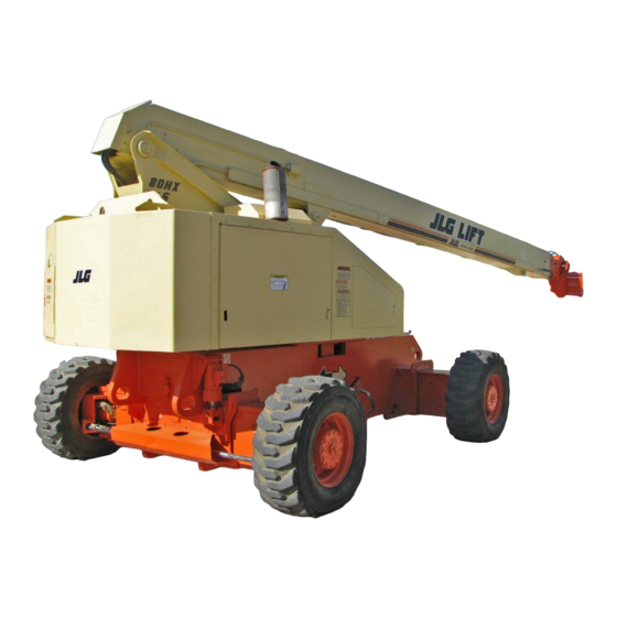
Model
80HX
80HX+6
80HXER
3120863
May 14, 2002
EUROPEAN OFFICE
JLG INDUSTRIES (EUROPE)
Kilmarting Place,
Tannochside Park
Uddingston, Scotland, G71 5PH
Telephone: 01698 811005
Main Fax: 01698 811055
Parts Fax: 01698 811455
CORPORATE OFFICE
JLG INDUSTRIES, INC.
1 JLG Drive
McConnellsburg, PA.
17233-9533
USA
Telephone: (717) 485-5161
Fax: (717) 485-6417
Advertisement
Table of Contents
Troubleshooting

Related Manuals for JLG 80HX


Summary of Contents for JLG 80HX
- Page 1 Model 80HX 80HX+6 80HXER 3120863 May 14, 2002 AUSTRALIAN OFFICE EUROPEAN OFFICE CORPORATE OFFICE JLG INDUSTRIES, INC. JLG INDUSTRIES (EUROPE) JLG INDUSTRIES, INC. P.O. Box 5119 Kilmarting Place, 1 JLG Drive 11 Bolwarra Road Tannochside Park McConnellsburg, PA. Port Macquarie, Australia...
-
Page 3: A General
Relieve system pressure by cycling the applicable control several times with the engine stopped and ignition on, to direct any line pressure back into the reservoir. Pressure 3120863 – JLG Lift –... - Page 4 INTRODUCTION REVISON LOG October, 1997 - Original Issue March 1, 1999 - Revised September 7, 2000 - Revised May 14, 2002 - Revised – JLG Lift – 3120863...
- Page 5 80HX w/Hydraulic Controls ........
-
Page 6: Table Of Contents
Limit Switch Adjustments ............2-29 – JLG Lift –... - Page 7 Hydraulic Circuit Checks............3-1 3120863 – JLG Lift –...
- Page 8 Hydraulic Schematic (Sheet 6 of 6) ..........3-29 – JLG Lift –...
- Page 9 Electrical System - Troubleshooting ..........3-18 3120863 – JLG Lift –...
- Page 10 TABLE OF CONTENTS (Continued) THIS PAGE LEFT BLANK INTENTIONALLY. – JLG Lift – 3120863...
-
Page 11: Capacities
Horsepower - 70 @ 2400 RPM, no load Tires Swing Motor - Displacement - 74 cc/Rev. Foam-Filled Tires - 15 x 19.5 Swing Hub - Ratio - 69.50:1. Swing Brake - Automatic spring applied, hydrau- lically released disc brakes. 3120863 – JLG Lift –... -
Page 12: Hydraulic Pump
Machines with Vickers Valves. Machine Weight First Section to Proportional Valve-Drive, Lift, Swing - 57 LPM. 80HX - approx. 14,424 KG. Second Section to High Drive - 34 LPM. 80HX+6 - approx. 16,738 KG. Machine Stowed Height Third Section to Bang-Bang Valve Level, Telescope, Steer, Rotate - 34 LPM. - Page 13 SECTION 1 - SPECIFICATIONS 3120863 – JLG Lift –...
-
Page 14: Maximum Tire Load
SECTION 1 - SPECIFICATIONS Maximum Tire Load 1.5 LUBRICATION 80HX - 17037 kg @ 7.2 kg/cm Deutz Engine 80HX + 6 - 8299 kg @ 7.5 kg/cm Single Viscosity Oils (CD-SE, CD-SF). When Outside Temp Use SAE Wheelbase is Consistently Viscosity Number -29°... -
Page 15: Lubrication Specifications
1200 hours = 2 years Specific Gravity .877 -40°F (-40°C) Pour Point, Max 330°F (166°C) Flash Point, Min. Viscosity at 104° F (40° C) 33 cSt at 212° F (100° C) 6.5 cSt Viscosity Index 3120863 – JLG Lift –... -
Page 16: Lubrication Diagram
SECTION 1 - SPECIFICATIONS Figure 1-2. Lubrication Diagram – JLG Lift – 3120863... -
Page 17: Lubrication Chart
Align access holes in mid and fly boom. Sheave 2 Grease Fittings Remote Access Swing Bearing Lift Cylinder (Barrel End) 1 Grease Fitting Remote Access Master Cylinder (Barrel 1 Grease Fitting Remote Access End) Master Cylinder (Rod 1 Grease Fitting End) 3120863 – JLG Lift –... - Page 18 (Extendable Axles) Oscillating Axle Pivot 1 Grease Fitting Oscillation Cylinder 2 Grease Fittings Extend-A-Reach Pivot (If 2 Grease Fittings Equipped) Extend-A-Reach Lift 1 Grease Fitting Cylinder (Barrel End) 1 Grease Fitting Extend-A-Reach Lift Cylinder (Rod End) – JLG Lift – 3120863...
- Page 19 Lubrication intervals are based on machine operation under normal conditions. For machines used in multi shift operations and/or exposed to hostile envi- Engine Oil ronments or conditions, lubrication frequencies must be increased accordingly. EPGL Extreme Pressure Gear Lube Hydraulic Fluid (Mobil #424 or equivalent) Multi-Purpose Grease 3120863 – JLG Lift –...
-
Page 20: Pressure Settings
SECTION 1 - SPECIFICATIONS Extend-A-Reach Down - 76 Bar. 1.6 PRESSURE SETTINGS 80HX w/Oscillating Axle NOTE: All pressure are given in pounds per square inch (psi), with the metric equivalent, Bar, in parentheses. Proportional Relief - Standard 220 Bar; Prop. Tele 265 Bar. -
Page 21: Major Components Weights
Complete Machine - 2WD No Options 28605 12973 Engines Deutz F4L912 Complete Machine - 4WD No Options 29106 13200 Ford LRG 423 Complete Machine (80HX+6) 2WD No Options 14447 31856 Cummins 4B3.9 Tire & Wheels 15x19.5 Tire 1.8 CYLINDER SPECIFICATIONS Table 1-8. Cylinder Specifications Wheel... -
Page 22: Serial Number Location
If the serial number plate is damaged or miss- ing, the machine serial number is stamped on the left side of the frame between front and rear wheels, below turnta- Figure 1-3. Serial Number Locations 1-12 – JLG Lift – 3120863... -
Page 23: Component Disassembly And Reassembly
Shields, covers, seals, and filters are provided to keep air, fuel, and oil supplies clean; however, these items must be maintained on a scheduled basis in order to function properly. 3120863 – JLG Lift –... -
Page 24: Bearings
Hydraulic system filters should checked, cleaned, and/or replaced as necessary, at the speci- fied intervals required in Section 1. Always examine filters for evidence of metal particles. – JLG Lift – 3120863... -
Page 25: Hydraulic Oil
Should any question arise, regarding the use of greases in maintenance stock, consult your local supplier for evalua- 2. JLG recommends Mobilfluid 424 hydraulic oil, which tion. Refer to Section 1 for an explanation of the lubricant has an SAE viscosity of 10W-20 and a viscosity key designations appearing in the Lubrication Chart. -
Page 26: Cylinders - Theory Of Operation
– JLG Lift – 3120863... -
Page 27: Proportional Control Valve
SECTION 2 - PROCEDURES Figure 2-1. Proportional Control Valve 3120863 – JLG Lift –... -
Page 28: Boom Chains (See Figure 2-2.)
10. Fully extend and retract the boom and check for 2.6 BOOM CHAINS (SEE FIGURE 2-2.) proper operation. JLG Industries, Inc. requires a complete boom disassem- Adjusting Procedures bly, per instructions outlined in Section 2.12, Boom Main- tenance, every two years. All boom chains and related components (i.e., sheaves, pins, sprockets, wear pads,... -
Page 29: Inspection Procedures
Fatigue and ultimate strength failures on repair chains; if a section of chain is damaged, JLG Lifts are incurred as a result of severe abuse as replace the entire chain set. design specs are well within the rated lifting capacity of these chains. -
Page 30: Auxiliary Boom Chains
8. Chain Anchors, Sheaves and Pins: An inspection of the chain must include a close examination of chain anchors, sheaves and pins. Check chain REPLACE THE BELLEVILLE WASHERS ONCE THEY HAVE BEEN anchors for wear breakage and misalignment. COMPRESSED. – JLG Lift – 3120863... -
Page 31: Wear Pads
If leakage continues at a rate of 6-8 drops per minute or more, cylinder repairs must be made. 5. With the cylinder fully retracted, shut down the engine and carefully disconnect the hydraulic hose from the cylinder extend port. 3120863 – JLG Lift –... -
Page 32: Cylinders With Single Counterbalance Valve - Lift Cylinder, Telescope Cylinder And Extend- A-Reach Lift Cylinder
7. If used, remove the lifting device from the upright or remove the prop from below the boom, activate the hydraulic system and run the cylinder through one complete cycle to check for leaks. 2-10 – JLG Lift – 3120863... -
Page 33: Cylinder Repair
NOTE: Step 4 applies only to the Telescope Cylinder. 4. Remove the nuts which attach each cylinder rod support block pull rod and withdraw the rods from the forward end of the telescope cylinder. 3120863 – JLG Lift – 2-11... -
Page 34: Typical Hydraulic Cylinders (Sheet 1 Of 4)
SECTION 2 - PROCEDURES Figure 2-5. Typical Hydraulic Cylinders (Sheet 1 of 4) 2-12 – JLG Lift – 3120863... -
Page 35: Typical Hydraulic Cylinders (Sheet 2 Of 4)
SECTION 2 - PROCEDURES Figure 2-6. Typical Hydraulic Cylinders (Sheet 2 of 4) 3120863 – JLG Lift – 2-13... -
Page 36: Typical Hydraulic Cylinders (Sheet 3 Of 4)
SECTION 2 - PROCEDURES Figure 2-7. Typical Hydraulic Cylinders (Sheet 3 of 4) 2-14 – JLG Lift – 3120863... -
Page 37: Typical Hydraulic Cylinders (Sheet 4 Of 4)
SECTION 2 - PROCEDURES Figure 2-8. Typical Hydraulic Cylinders (Sheet 4 of 4) 3120863 – JLG Lift – 2-15... -
Page 38: Cleaning And Inspection
Dress the threads as necessary. damage. Replace as necessary. 4. Inspect the inner surface of the cylinder barrel tube for scoring or other damage. Check the inside diam- eter for tapering or ovality. Replace if necessary. 2-16 – JLG Lift – 3120863... -
Page 39: Assembly
8. Push the piston onto the rod until it abuts the spacer NOTE: Prior to cylinder assembly, ensure that the proper end and install the attaching nut. cylinder seal kit is used. See your JLG Parts Manual. Apply a light film of hydraulic oil to all components prior to assembly. - Page 40 19. If applicable, install the cartridge-type holding valve and fittings in the rod port block using new o-rings as applicable. (See Table 2-3, Holding Valve Torque Specification). 2-18 – JLG Lift – 3120863...
-
Page 41: Cylinder Removal And Installation
8. Remove the capscrews securing the trunnion pins from each side of the boom. 9. Using a suitable slide hammer, remove the trunnion pins attaching the telescope cylinder to the mid boom. 3120863 – JLG Lift – 2-19... -
Page 42: Telescope Cylinder Installation
5. Attach the cylinder rod support bracket to the rod completely. support block on the telescope cylinder. 6. Install the chain adjust block with four (4) lock- washer and bolts to the base boom section. 2-20 – JLG Lift – 3120863... -
Page 43: Boom Lift Cylinder Installation
2. Remove the slave leveling cylinder from the boom assembly. NOTE: The boom assembly weighs approximately 2200 kg. 3. Using suitable lifting equipment, adequately support the boom weight along the entire length of the retracted boom. 3120863 – JLG Lift – 2-21... -
Page 44: Boom Assembly (Sheet 1 Of 2)
SECTION 2 - PROCEDURES Figure 2-12. Boom Assembly (Sheet 1 of 2) 2-22 – JLG Lift – 3120863... -
Page 45: Boom Assembly (Sheet 2 Of 2)
SECTION 2 - PROCEDURES Figure 2-13. Boom Assembly (Sheet 2 of 2) 3120863 – JLG Lift – 2-23... -
Page 46: Disassembly
4. Remove the carrier tube and power track from the assembled mid and fly sections from the base sec- right side of the boom assembly. tion. Place the mid and fly sections on a suitable trestle. 2-24 – JLG Lift – 3120863... -
Page 47: Inspection
18. Remove the bolts which secure the wear pads to the components for cracks, stretching, distortion, or aft ends of the fly and mid sections; remove the wear other damage. Replace components as necessary. pads from the boom sections. 3120863 – JLG Lift – 2-25... -
Page 48: Assembly
Place the chain block weldment in position at the aft end of the fly section; secure the weldment by installing the bolts and washers. 2-26 – JLG Lift – 3120863... - Page 49 Insert chain attach blocks between the clevis plates ensuring the attachment points are prop- erly aligned. Secure the block in position with bolts, nuts and new cotter pins. 3120863 – JLG Lift – 2-27...
-
Page 50: Installation
5. Divide the number of turns determined in step 4 in half. Tighten the nut this many turns. The line deter- mined by this nut and the “X” nut is now parallel to the ground. 2-28 – JLG Lift – 3120863... -
Page 51: Voltmeter Adjustment
Adjust the switch to activate when the work plat- 5. Check voltage at the trip point in all four directions. If form reaches a height of 8 meters. the voltage reading is not symmetrical, repeat step 4 above. 3120863 – JLG Lift – 2-29... -
Page 52: Throttle Checks And Adjustments - Deutz Engine (See Figure 2-16.)
Turn on HIGH ENGINE switch. Hold drive controller in full drive position. Adjust slide pin to contact high engine limit switch at 2400 RPM. Shut off all switches and controllers. Reconnect propor- tional dump valve wire. 2-30 – JLG Lift – 3120863... -
Page 53: Adeco Actuator Adjustments - F4L912
SECTION 2 - PROCEDURES Figure 2-16. Adeco Actuator Adjustments - F4L912 3120863 – JLG Lift – 2-31... -
Page 54: Pressure Setting Procedures
Figure 2-17. Racine Proportional Air Gap Adjustment, Machines Built Prior to Mid 1987 2-32 – JLG Lift – 3120863... -
Page 55: Vickers Proportional Valve Pressure Setting - Mid 1992 To Present (Sheet 1 Of 4)
SECTION 2 - PROCEDURES Figure 2-18. Vickers Proportional Valve Pressure Setting - Mid 1992 to Present (Sheet 1 of 4) 3120863 – JLG Lift – 2-33... -
Page 56: Vickers Proportional Valve Pressure Setting - Mid 1992 To Present (Sheet 2 Of 4)
SECTION 2 - PROCEDURES Figure 2-19. Vickers Proportional Valve Pressure Setting - Mid 1992 to Present (Sheet 2 of 4) 2-34 – JLG Lift – 3120863... -
Page 57: Vickers Proportional Valve Pressure Setting - Mid 1992 To Present (Sheet 3 Of 4)
SECTION 2 - PROCEDURES Figure 2-20. Vickers Proportional Valve Pressure Setting - Mid 1992 to Present (Sheet 3 of 4) 3120863 – JLG Lift – 2-35... -
Page 58: Vickers Proportional Valve Pressure Setting - Mid 1992 To Present (Sheet 4 Of 4)
SECTION 2 - PROCEDURES Figure 2-21. Vickers Proportional Valve Pressure Setting - Mid 1992 to Present (Sheet 4 of 4) 2-36 – JLG Lift – 3120863... -
Page 59: Pressure Setting - All Hydraulic Machines (Sheet 1 Of 4)
SECTION 2 - PROCEDURES Figure 2-22. Pressure Setting - All Hydraulic Machines (Sheet 1 of 4) 3120863 – JLG Lift – 2-37... -
Page 60: Pressure Setting - All Hydraulic Machines (Sheet 2 Of 4)
SECTION 2 - PROCEDURES Figure 2-23. Pressure Setting - All Hydraulic Machines (Sheet 2 of 4) 2-38 – JLG Lift – 3120863... -
Page 61: Pressure Setting - All Hydraulic Machines (Sheet 3 Of 4)
SECTION 2 - PROCEDURES Figure 2-24. Pressure Setting - All Hydraulic Machines (Sheet 3 of 4) 3120863 – JLG Lift – 2-39... -
Page 62: Pressure Setting - All Hydraulic Machines (Sheet 4 Of 4)
SECTION 2 - PROCEDURES Figure 2-25. Pressure Setting - All Hydraulic Machines (Sheet 4 of 4) 2-40 – JLG Lift – 3120863... -
Page 63: Solenoid Valve Pressure Settings - Machines Built To Present
SECTION 2 - PROCEDURES Figure 2-26. Solenoid Valve Pressure Settings - Machines Built to Present 3120863 – JLG Lift – 2-41... -
Page 64: Solenoid Valve Pressure Settings - 4 Wheel Steer
SECTION 2 - PROCEDURES Figure 2-27. Solenoid Valve Pressure Settings - 4 Wheel Steer 2-42 – JLG Lift – 3120863... -
Page 65: Extend-A-Reach Valve Pressure And Speed Settings
SECTION 2 - PROCEDURES Figure 2-28. Extend-A-Reach Valve Pressure and Speed Settings 3120863 – JLG Lift – 2-43... -
Page 66: Swing Bearing
NOTE: This check is designed to replace the existing bear- 0.0015" feeler gauge between the bolt head and ing bolt torque checks on JLG Lifts in service. This hardened washer at the arrow indicated position. check must be performed after the first 50 hours of 3. -
Page 67: Wear Tolerance
RETORQUE THE INNER AND OUTER SWING BEARING BOLTS a. Metal particles in the grease. AFTER FIRST 200 HOURS OF OPERATION, AND EVERY 500 HOURS THEREAFTER. b. Increased drive power required. c. Noise. d. Rough rotation. 3120863 – JLG Lift – 2-45... -
Page 68: Swing Bearing Torquing Sequence
SECTION 2 - PROCEDURES Figure 2-32. Swing Bearing Torquing Sequence 2-46 – JLG Lift – 3120863... -
Page 69: Torque Hub (See Figure 2-33.)
With seal removed, outside bearing cone (4) can be removed. 10. If necessary, remove inner and outer bearing cones (3,5) using a suitable slide hammer puller. WHEN REBUILDING TORQUE HUB, REMOVE AND REPLACE ALL O-RINGS AND RETAINING RINGS. 3120863 – JLG Lift – 2-47... -
Page 70: Torque Hub Assembly
SECTION 2 - PROCEDURES Figure 2-33. Torque Hub Assembly 2-48 – JLG Lift – 3120863... -
Page 71: Repair
2. Using a suitable press, press planet shaft from car- rier 13. After planet shaft is removed, drive anti-roll pin from shaft. 3. Remove cluster gear (18) and thrust washers (20,14) from carriers. 4. Remove sixteen needle rollers (15) from cluster gear bore. 3120863 – JLG Lift – 2-49... - Page 72 15. Drive anti-roll pin flush into carrier hole, locking planet shaft into place. 16. Repeat steps 8 thru 15 for remaining two cluster gears. 2-50 – JLG Lift – 3120863...
-
Page 73: Input Shaft Assembly
3. Press new seal (2) into hub counterbore with flat spacers and spring to shaft. metal side facing in. Use a flat object to ensure that seal is pressed evenly and is flush with hub face. 3120863 – JLG Lift – 2-51... - Page 74 6. Place bearing shim (8) over end of spindle and against bearing cone. 9. Install thrust washers and thrust bearing (39, 40) on the portion of the spindle which extends into the EYE PROTECTION SHOULD BE WORN DURING RETAINING RING internal gear. INSTALLATION. 2-52 – JLG Lift – 3120863...
- Page 75 Find punch marked tooth on each large gear and locate at 12 o’clock (straight up) from each planet pin. Marked tooth will be located just under carrier on upper two gears. 3120863 – JLG Lift – 2-53...
- Page 76 Use petroleum jelly or grease to hold o-ring in place. 18. Install input gear (37) into carrier, meshing with small diameter cluster gears (18). Counterbore in bore of input gear must be to outside of carrier assembly. 2-54 – JLG Lift – 3120863...
-
Page 77: Drive Brake, Ausco - Machines Built Prior To 1992
4. Remove seal 4. 8. Remove springs (6) and spring retainer (5) from housing. 9. Remove piston (13) from power plate by introducing low pressure air (1 Bar) into hydraulic inlet. Direct piston away from operator. 3120863 – JLG Lift – 2-55... -
Page 78: Drive Brake, Ausco - Machines Built Prior To 1992
SECTION 2 - PROCEDURES Figure 2-34. Drive Brake, Ausco - Machines Built Prior to 1992 2-56 – JLG Lift – 3120863... -
Page 79: Cleaning And Inspection
(14) from end cover (13). 3. Remove piston (24) from end cover (13). 4. Remove o-ring (20), back-up ring (21), o-ring (18) and back-up ring (19) from piston (24). 5. Remove separators (10) from housing (7). 3120863 – JLG Lift – 2-57... -
Page 80: Drive Brake, Mico - Machines Built From 1992 To Present
SECTION 2 - PROCEDURES Figure 2-35. Drive Brake, Mico - Machines Built from 1992 to Present 2-58 – JLG Lift – 3120863... -
Page 81: Inspection
11. Install new case seal (11) in housing (7) then install bleeder screw (14) in end cover (13). 12. Position end cover (13) on housing (7) aligning dowel pins (17) with holes in end cover. 3120863 – JLG Lift – 2-59... -
Page 82: Controllers
7. Use a bar as a lever to press down on the cam valve 5. Place LOW ENGINE, HIGH DRIVE SPEED and HIGH plunger which will allow the axle to fully oscillate WHEEL MOTOR SPEED control switches to their against the stop. respective HIGH positions. 2-60 – JLG Lift – 3120863... -
Page 83: Oscillating Axle Lockout Test
REVERSE and drive machine off of block and ramp. Figure 2-37. Belleville Washers 7. Have an assistant check to see that left front wheel remains locked in position off of ground. 3120863 – JLG Lift – 2-61... -
Page 84: Free Wheeling Option
Any time pump or pump drive coupling is removed coat pump and drive coupling splines with Lithium Soap Base 3. Close the hand valve on the LP gas supply tank by Grease (TEXACO CODE 1912 OR EQUIVALENT) prior to turning clockwise. assembly. 2-62 – JLG Lift – 3120863... -
Page 85: Preventive Maintenance And Inspection Schedule
Inspection Report” form. Forms are supplied with each 13. Check for evidence of scratches, nicks or rust and new machine and are also available from JLG Customer for straightness of rod. Service. Form must be completed and returned to JLG Industries. -
Page 86: Preventive Maintenance And Inspection Schedule
5,11 Footswitch 1,11 1,11 Controllers 1,11 Switches Placards and Decals Control Tags 1,11 Valves Carrier (Hoses and Cables) Hydraulic Hoses Capacity Indicator Pins Bushings Wear Pads Chains Chain Adjusters 1,5,6,13 Cylinders Sheaves Drift Test* 2-64 – JLG Lift – 3120863... - Page 87 Auxiliary Power Pump 1,11 Valves Hydraulic Filters Hydraulic Hoses Hydraulic Oil Tank** 6,14 Breather Hydraulic Tank Fuel Tank Cylinders 1,5,6,13 Hood Doors Placards and Decals 9, 12 Swing Bearing Swing Brake 1,5,6 Swing Hub 3120863 – JLG Lift – 2-65...
-
Page 88: Capacity Indicator
AN ACCURATE READING OF THE CAPACITY INDICATOR GAGE. Installation Procedure 1. Clean and dry fly boom top surface before installing the tape. 2. install tape on center of fly boom to dimensions shown in table. Figure 2-39. Capacity indicator Dial 2-66 – JLG Lift – 3120863... -
Page 89: Section 3. Troubleshooting
For aid in troubleshooting, refer to It should be noted that there is no substitute for a thor- the illustrated parts manual for hydraulic diagrams of the ough knowledge of the equipment and related systems. various circuits. 3120863 – JLG Lift –... -
Page 90: Platform Assembly - Troubleshooting
Repair or replace pump. Restricted or broken hydraulic line or fitting. Clean, repair, or replace line or fitting. Slave cylinder not functioning properly. Repair or replace cylinder. Electrical failure. See proper wiring diagram. Orifice plugged. Clean orifice. – JLG Lift – 3120863... -
Page 91: 3120863 - Jlg Lift
Determine cause and repair or replace valve. Electrical malfunction. See wiring diagram. Hydraulic system oil low. Replenish oil as necessary. Restricted or broken supply line on valve bank or Clean or replace line. hydraulic pump. 3120863 – JLG Lift –... - Page 92 Control valve not functioning properly. Repair or replace valve. Worn seals in lift cylinder. Replace seals. Cylinder not functioning properly. Repair or replace cylinder. Boom drifts down. Worn seals in lift cylinder. Replace seals. – JLG Lift – 3120863...
- Page 93 Repair or replace control valve. Restricted or broken hydraulic line or fitting. Clean, repair, or replace line or fitting. Pressure setting incorrect. Check pressure/re-adjust as necessary. Telescope cylinder not functioning properly. Repair or replace cylinder. 3120863 – JLG Lift –...
- Page 94 Repair or replace valve. Foreign object(s) wedged between swing motor Remove object(s), check for damage and repair pinion and swing gear. or replace component(s) as required. Swing control switch not functioning properly. Repair or replace swing control switch. – JLG Lift – 3120863...
- Page 95 Swing motor not functioning properly. Repair or replace swing control switch. Worn or broken teeth on swing gear or swing Replace gear(s) as required. motor pinion. Restrictor valves(s) plugged. Clean or replace restrictor valve. 3120863 – JLG Lift –...
-
Page 96: Turntable Assembly - Troubleshooting
Valve spool scored. Repair or replace valve. Excessive back pressure caused by restricted Remove line and clear obstruction or replace line return line to reservoir. as necessary. Damaged valve seals. Repair or replace valve as necessary. – JLG Lift – 3120863... -
Page 97: Chassis Assembly - Troubleshooting
Damaged wiring on speed control switch or high Repair or replace wiring. engine solenoid. Drive controller not functioning properly. Replace controller. Actuator not functioning properly. Repair or replace solenoid. Excessive load on engine. Reduce load. 3120863 – JLG Lift –... - Page 98 Machine being moved up too steep a grade. Remove machine from grade and check that drive system operates correctly. Grade too steep. See WARNING Placard on platform for specified grades and sideslopes. Towing valve not closed. Close towing valve. 3-10 – JLG Lift – 3120863...
- Page 99 Repair or replace motor(s). Circuit breaker open. Determine and correct cause; reset circuit breaker. Counterbalance valve sticking on return side. Adjust return counterbalance out 3 turns - cycle drive - return to original position. 3120863 – JLG Lift – 3-11...
- Page 100 Damaged wiring on control switch or solenoid See proper wiring diagram. valve. Control switch not functioning properly. Replace switch. Restricted or broken hydraulic line on valve Clean, repair or replace line. bank, hydraulic pump or rotary coupling. (If equipped.) 3-12 – JLG Lift – 3120863...
- Page 101 Take pressure reading at steer valve and adjust as necessary. Bent cylinder rod. Repair or replace cylinder. Damaged tie rod. Replace tie rod. Crossover relief valve sticking. Repair crossover relief valve. Cylinder packing defective. Repair or replace cylinder. 3120863 – JLG Lift – 3-13...
- Page 102 Crossover relief valve set too low or not function- Reset, repair or replace valve as required. ing properly. Steer linkages loose. Tighten linkage. Steer wheel toe-in not set properly. Adjust toe-in for 1/4 inch overall. Spindle bushings badly worn. Replace bushings. 3-14 – JLG Lift – 3120863...
-
Page 103: Hydraulic System - Troubleshooting
Main relief valve set too low. Reset valve as required. Hydraulic system oil low. Replenish oil as necessary. Port relief set too high. Reset valve as required. Restricted or blocked return line. Repair or replace line. 3120863 – JLG Lift – 3-15... - Page 104 Determine and correct cause; reset circuit breaker. Engine is running. Shut down engine. Check valve in system leaking. Repair or replace check valve. Battery requires charging or will not hold a Charge or replace battery as required. charge. 3-16 – JLG Lift – 3120863...
- Page 105 Control switch not functioning properly. Replace switch. Restricted or broken hydraulic line or fitting. Clean, repair or replace line or fitting. Pump motor solenoid not functioning properly. Replace solenoid. Pump motor not functioning properly. Repair or replace motor. 3120863 – JLG Lift – 3-17...
-
Page 106: Electrical System - Troubleshooting
Faulty ignition and/or starter circuit wiring. Check wiring continuity. See proper wiring dia- gram. Malfunctioning starter solenoid or motor. Replace solenoid or motor in accordance with applicable manufacturer’s manual. Faulty start switch. Replace switch. 3-18 – JLG Lift – 3120863... - Page 107 Repair or replace limit switch. Drive controller defective. Replace controller. High engine solenoid malfunctioning. Repair or replace solenoid valve. Drive pressure switch malfunctioning. Replace pressure switch. Electrical malfunction. See wiring diagram. Defective engine governor. Repair or replace governor. 3120863 – JLG Lift – 3-19...
-
Page 108: Wiring Schematic (Sheet 1 Of 4)
SECTION 3 - TROUBLESHOOTING Figure 3-1. Wiring Schematic (Sheet 1 of 4) 3-20 – JLG Lift – 3120863... -
Page 109: Wiring Schematic (Sheet 2 Of 4)
SECTION 3 - TROUBLESHOOTING 1870003A Figure 3-2. Wiring Schematic (Sheet 2 of 4) 3120863 – JLG Lift – 3-21... -
Page 110: Wiring Schematic (Sheet 3 Of 4)
SECTION 3 - TROUBLESHOOTING Figure 3-3. Wiring Schematic (Sheet 3 of 4) 3-22 – JLG Lift – 3120863... -
Page 111: Wiring Schematic (Sheet 4 Of 4)
SECTION 3 - TROUBLESHOOTING 1870003A Figure 3-4. Wiring Schematic (Sheet 4 of 4) 3120863 – JLG Lift – 3-23... -
Page 112: Hydraulic Schematic (Sheet 1 Of 6)
SECTION 3 - TROUBLESHOOTING Figure 3-5. Hydraulic Schematic (Sheet 1 of 6) 3-24 – JLG Lift – 3120863... -
Page 113: Hydraulic Schematic (Sheet 2 Of 6)
SECTION 3 - TROUBLESHOOTING 2792231- Figure 3-6. Hydraulic Schematic (Sheet 2 of 6) 3120863 – JLG Lift – 3-25... -
Page 114: Hydraulic Schematic (Sheet 3 Of 6)
SECTION 3 - TROUBLESHOOTING Figure 3-7. Hydraulic Schematic (Sheet 3 of 6) 3-26 – JLG Lift – 3120863... -
Page 115: Hydraulic Schematic (Sheet 4 Of 6)
SECTION 3 - TROUBLESHOOTING 2792231- Figure 3-8. Hydraulic Schematic (Sheet 4 of 6) 3120863 – JLG Lift – 3-27... -
Page 116: Hydraulic Schematic (Sheet 5 Of 6)
SECTION 3 - TROUBLESHOOTING Figure 3-9. Hydraulic Schematic (Sheet 5 of 6) 3-28 – JLG Lift – 3120863... -
Page 117: Hydraulic Schematic (Sheet 6 Of 6)
SECTION 3 - TROUBLESHOOTING 2792231- Figure 3-10. Hydraulic Schematic (Sheet 6 of 6) 3120863 – JLG Lift – 3-29... - Page 118 SECTION 3 - TROUBLESHOOTING This page left blank intentionally. 3-30 – JLG Lift – 3120863...
- Page 120 England Fax: (49) 421 693 5035 Fax: (61) 2 65 810122 Phone: (44) 870 200 7700 Fax: (44) 870 200 7711 JLG Latino Americana Ltda. JLG Europe B.V. JLG Industries (Norge AS) JLG Polska Rua Eng. Carlos Stevenson, Jupiterstraat 234 Sofeimyrveien 12 UI.
Need help?
Do you have a question about the 80HX and is the answer not in the manual?
Questions and answers