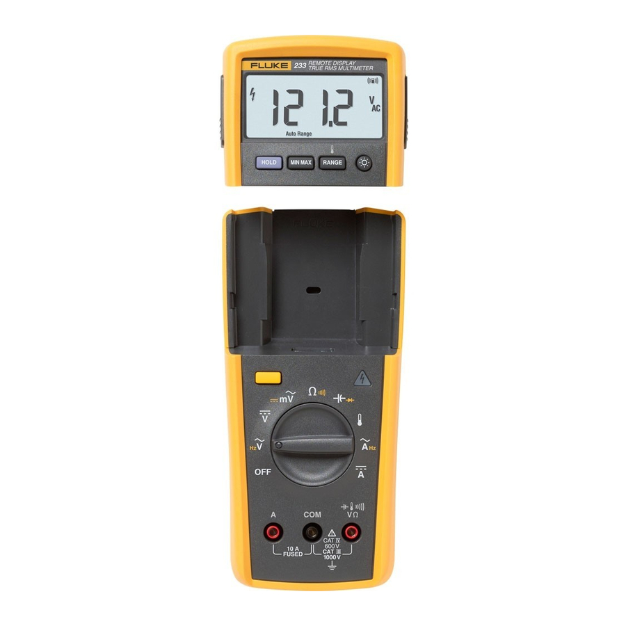
Fluke 233 Calibration Information Manual
True-rms remote display
Hide thumbs
Also See for 233:
- User manual ,
- Application manual (56 pages) ,
- Getting started manual (17 pages)
Table of Contents
Advertisement
Introduction
To avoid electric shock or injury, do not perform the performance tests or
calibration adjustment procedures unless qualified to do so.
The information provided in this document is for the use of qualified personnel
only.
The 233 Calibration Information provides the information necessary to adjust and verify the performance of the
Fluke Model 233 True-rms Remote Display Digital Multimeter (hereafter known as the Meter).
The following information is included in this document:
•
Safety Information and International Electrical Symbols (page 2)
•
Specifications (page 3)
•
Testing the Fuse (page 9)
•
Replacing the Fuse and the Battery (page 10)
•
Cleaning (page 10)
•
Performance Tests (page 11)
•
Calibration Adjustment (page 14)
•
Replacement Parts and Accessories (page 19)
•
Complete Warranty (page 21)
See the 233 Users Manual for complete operating instructions.
Contact Information
To contact Fluke, call one of the following telephone numbers:
USA: 1-888-99-FLUKE (1-888-993-5853)
Canada: 1-800-36-FLUKE (1-800-363-5853)
Europe: +31 402-675-200
Japan: +81-3-3434-0181
Singapore: +65-738-5655
Anywhere in the world: +1-425-446-5500
To register your product, visit
October 2009
©2009 Fluke Corporation. All rights reserved. Specifications are subject to change without notice.
True-rms Remote Display Digital Multimeter
XWWarning
register.fluke.com
233
Calibration Information
1
Advertisement
Table of Contents

Related Manuals for Fluke 233


Summary of Contents for Fluke 233
-
Page 1: Calibration Information
The information provided in this document is for the use of qualified personnel only. The 233 Calibration Information provides the information necessary to adjust and verify the performance of the Fluke Model 233 True-rms Remote Display Digital Multimeter (hereafter known as the Meter). -
Page 2: Safety Information
Calibration Information Safety Information A Warning identifies hazardous conditions and actions that could cause bodily harm or death. A Caution identifies conditions and actions that could damage the Meter, the equipment under test, or cause permanent loss of data. XWWarning To prevent possible electrical shock or personal injury, follow these guidelines: •... -
Page 3: International Electrical Symbols
Do not discard this product as unsorted municipal waste. Go to the Fluke website Diode for recycling data. Examined and licensed by TÜV Product ®... -
Page 4: Detailed Specifications
Calibration Information Relative Humidity............Maximum noncondensing 90 % at 35 °C 75 % at 40 °C 45 % at 50 °C 0 % to 70 % for 40 MΩ range Battery Type Meter base..............Three AA Alkaline batteries, NEDA 15A IEC LR6 Display module ............ - Page 5 True-rms Remote Display Digital Multimeter Detailed Specifications Temperature Range Resolution Accuracy -40 °C to +400 °C 0.1 °C ±(1.0 % + 10) -40 °F to +752 °F 0.1 °F ±(1.0 % + 18) Temperature uncertainty (accuracy) does not include error of the thermocouple probe. AC Current Accuracy Function...
-
Page 6: Input Characteristics
Calibration Information Input Characteristics Input Common Mode Overload Function Impedance Rejection Ratio Normal Mode Rejection Protection (nominal) (1 kΩ unbalance) 1100 V >10 MΩ <100 > 100 dB at dc, 50 Hz > 60 dB at 50 Hz or 60 Hz or 60 Hz 1100 V >5 MΩ... -
Page 7: Battery Replacement
True-rms Remote Display Digital Multimeter Battery Replacement Battery Replacement XWWarning To prevent incorrect measurements, possible electrical shock, or personal injury, replace the battery when the battery indicator () appears. If the display shows , the Meter will not function until the display module batteries are replaced. If the display shows ... -
Page 8: Remove The Display Module
Calibration Information Remove the Display Module To remove the display module (see Figure 2): 1. Push in on the latches on the sides of the display module. 2. Pull the display module off of the top end of the Meter base. The Meter base and display module can be a maximum of 10 Meters (30 feet) from each other before the radio connection is broken. -
Page 9: Fuse Test
True-rms Remote Display Digital Multimeter Fuse Test gcc111.eps Figure 3. Display-Module Battery Removal Fuse Test To test the fuse: 1. Set the rotary switch to Ω 2. Plug a test lead into the v jack and touch the probe to the 10A jack, as shown in Figure 0-4. If the display shows a resistance value in the range of that shown in Figure 0-4, the fuse is good. -
Page 10: Fuse Replacement
5. Remove the fuse from its holder and replace it with an 11 A, 1000 V, FAST fuse with a minimum interrupt rating of 17,000 A. Use only Fluke PN 803293. To re-assemble the Meter, do the steps above in the opposite sequence. -
Page 11: Performance Tests
9 to 900 μF Capacitance ±0.475 % 0 °C to 400 °C ±0.25 % Temperature 5500A Multi-product Calibrator (or Frequency 2 V, 50 kHz ±0.025 % equivalent) Fluke 80 AK Temperature K-type Thermocouple Adapter Accessory K-type Thermocouple, mini-plug on both Temperature ends... - Page 12 Calibration Information Testing the Display Push K and turn the rotary switch to the e position. Compare the display with the example in Figure 6. Check all segments for clarity and contrast. erc022f.emf Figure 6. Display Segments Backlight Test To Test the Backlight, press Q and verify that the backlight comes on. Keypad Test To test the keypad, turn the Meter to ACV and push each button separately.
-
Page 13: Temperature Tests
True-rms Remote Display Digital Multimeter Performance Tests 3. Apply the input level for each step listed in Table 3. 4. Compare the reading on the Meter display with the Display Reading in Table 3. 5. If the display reading falls outside of the range shown in Table 3, the Meter requires calibration adjustment or repair. -
Page 14: Calibration Adjustment
-1.0 to 1.0 400 °C 395.0 to 405.0 [1] If using a Fluke 9100 calibrator, the Calibrator Frequency mode must be used to obtain accurate frequency. Calibration Adjustment The Meter features closed-case calibration adjustment using known reference sources. The Meter measures the applied reference source, calculates correction factors, and stores the correction factors in nonvolatile memory. - Page 15 True-rms Remote Display Digital Multimeter Calibration Adjustment 3. Turn the rotary switch to OFF. Calibration Adjustment Password To start the Calibration Adjustment Procedure, the correct 4-digit password must be entered. The default password is “1234”. The password can be changed or reset to the default as described in following paragraphs. Changing the Password Use the following steps to change the Meter’s password: 1.
- Page 16 Calibration Information S103 XBT101 XBT102 erc12f.emf Figure 7. Calibration Password Reset Meter Buttons Used in the Calibration Steps When performing the Calibration Adjustment Procedure, the Meter buttons behave as follows. This may be of help in determining why a calibration step is not accepted and for determining the input value without referring to Table 4.
- Page 17 True-rms Remote Display Digital Multimeter Calibration Adjustment Note Some adjustment steps require additional wait time after the calibrator settles, as noted in Table 4. 7. After each input value is applied, press g to accept the value and proceed to the next step (C-02 and so forth).
- Page 18 Calibration Information Table 4. Calibration Adjustment Steps Rotary Input Calibrator Switch Calibration Steps Terminals Source Value Position C-01 VΩ/+ and COM 0 V, 0 Hz C-02 VΩ/+ and COM 300 mV, 0 Hz C-03 VΩ/+ and COM 100 mV, 0 Hz C-04 VΩ/+ and COM -300 mV, 0 Hz...
-
Page 19: Replacement Parts
LCD RDX 3385697 FLUKE-233-8004,BACKLIGHT DIFFUSER 3385715 FLUKE-233-8008,KEYPAD, DISPLAY 3383900 MP5 MP6 FLUKE-233-8003,SPRING LATCH 3383917 FLUKE-233-2501,MASK PAD XFER 3383820 FLUKE-233-2501-01,MASK PAD XFER SI (Japan) 3470114 FLUKE-233-2008,BUTTON, LATCH, RIGHT 3383796 FLUKE-233-2008-01,BUTTON, LATCH, LEFT 3383801 MP10 FLUKE-233-2006,BATTERY DOOR, DISPLAY 3383770 MP11 FLUKE-233-2004,CASE BOTTOM, DISPLAY 3383755 CONNECTOR,ELASTOMERIC,.010 IN CTR,.218 IN HIGH,.090 IN... - Page 20 Calibration Information MP12 MP11 BT 1, 2 MP13 MP15 MP10 MP14 MP17 MP18 MP16 MP19 MP21 MP23 MP24 MP20 BT 3, 4, 5 MP22 MP13 Figure 8. Replaceable Parts...
-
Page 21: Warranty
Warranty Warranty This Fluke product will be free from defects in material and workmanship for three years from the date of purchase. This warranty does not cover fuses, disposable batteries, or damage from accident, neglect, misuse, alteration, contamination, or abnormal conditions of operation or handling. - Page 22 Calibration Information...
Need help?
Do you have a question about the 233 and is the answer not in the manual?
Questions and answers