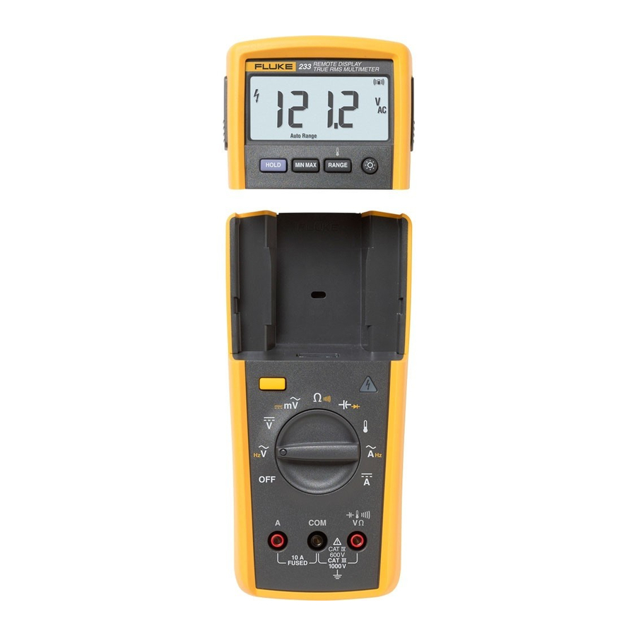
Fluke 233 Getting Started Manual
True-rms remote display digital multimeter
Hide thumbs
Also See for 233:
- User manual ,
- Application manual (56 pages) ,
- Calibration information manual (23 pages)
Table of Contents
Advertisement
Quick Links
Advertisement
Table of Contents

Related Manuals for Fluke 233


Summary of Contents for Fluke 233
- Page 1 Getting Started Manual True-rms Remote Display Digital Multimeter PN 3465366 September 2009 © 2009 Fluke Corporation. All rights reserved. Printed in USA. Specifications are subject to change without notice. All product names are trademarks of their respective companies.
- Page 2 LIMITED WARRANTY AND LIMITATION OF LIABILITY This Fluke product will be free from defects in material and workmanship for three years from the date of purchase. This warranty does not cover fuses, disposable batteries, or damage from accident, neglect, misuse, alteration, contamination, or abnormal conditions of operation or handling.
-
Page 3: How To Contact Fluke
Introduction The Fluke 233 (hereafter the Meter) is a compact and easy to operate tool for electrical and electronic circuit measurements. XWWarning Read "Safety Information" before you use the Meter. How to Contact Fluke Use one of the telephone numbers below to speak with a... -
Page 4: Safety Information
Getting Started Manual Safety Information XWWarning To prevent possible electrical shock or The Meter complies with: personal injury, follow these guidelines: ISA-82.02.01 Use this Meter only as specified in this CAN/CSA C22.2 No. 61010-1-04 manual or the protection can be ANSI/UL 61010-1:2004 compromised. - Page 5 True-rms Remote Display Digital Multimeter Safety Information Remove the test leads from the Meter For current measurements, connect the before the battery door on the Meter Meter to the circuit after you remove base is opened. circuit power. Always put the Meter in series with the circuit.
- Page 6 Getting Started Manual Use only specified 1.5-V AA batteries WCaution (three in the Meter base and two in the To prevent damage to the Meter or to the display), correctly installed, for Meter equipment under test, follow these power. guidelines: Comply with local and national safety Disconnect circuit power and discharge requirements when in hazardous...
- Page 7 Do not discard this product as unsorted municipal waste. Go to the Fluke website Diode for recycling data. Examined and licensed by TÜV Product ®...
- Page 8 Getting Started Manual Features See Tables 3 through 4 for a list of Meter features with a short feature description. Table 2. Display meter remote Auto RangeManual Range gcc101.eps Symbol Indication MIN MAX AVG mode on. MAX MIN AVG Maximum, minimum, or average measurement shown.
- Page 9 True-rms Remote Display Digital Multimeter Features Table 2. Display (cont.) Symbol Indication Radio connection indicator. C, F degrees Celsius, degrees Fahrenheit amperes (amps) volts, millivolts V, mV F, nF microfarad, nanofarad DC AC Direct current or alternating current. , M , k ohm, megohm, kilohm hertz, kilohertz Hz, kHz...
- Page 10 Getting Started Manual Table 3. Inputs gcc110.eps Terminal Description Input for 0 A to 10.00 A current measurements. Common terminal for all measurements. Input for voltage, continuity, resistance, diode, capacitance, temperature, and frequency measurements.
- Page 11 True-rms Remote Display Digital Multimeter Features Table 4. Function Switch Positions Switch Description Position AC voltage from 0.06 to 1000 V. Frequency from 5 Hz to 50 kHz. Hz (button) DC voltage from 0.001 V to 1000 V. ...
-
Page 12: Error Messages
Getting Started Manual Error Messages Table 5 contains possible error messages and the steps to clear the error. Table 5. Error Messages Error Messages Display-module batteries must be replaced before the Meter will operate. Meter-base batteries must be replaced before the Meter will operate. ... -
Page 13: Remote Operation
True-rms Remote Display Digital Multimeter Remote Operation Remote Operation gcc114.eps gcc115.eps Figure 1. Display Module Separation Figure 2. Dock Display Module with Meter Base... -
Page 14: Battery Replacement
Getting Started Manual Fuse Test Battery Replacement Good fuse: 0.0 Ω to 0.5 Ω Replace fuse: OL gcc111.eps Figure 4. Display-Module Battery Removal gcc105.eps Figure 3. Fuse Test... - Page 15 True-rms Remote Display Digital Multimeter Battery Replacement gcc112.eps Figure 5. Meter Base Battery Replacement...
-
Page 16: General Specifications
Getting Started Manual General Specifications Maximum voltage between any terminal and earth ground ........... 1000 V rms W Fuse for A inputs ............. 11 A, 1000 V 17000A interrupt rating Fuse Altitude Operating ..............2,000 meters Storage ............... 12,000 meters Temperature Operating ..............
Need help?
Do you have a question about the 233 and is the answer not in the manual?
Questions and answers