Fluke 233 User Manual
True-rms remote display digital multimeter
Hide thumbs
Also See for 233:
- User manual ,
- Application manual (56 pages) ,
- Calibration information manual (23 pages)
Table of Contents

Related Manuals for Fluke 233


Summary of Contents for Fluke 233
- Page 1 True-rms Remote Display Digital Multimeter Users Manual September 2009 © 2009 Fluke Corporation. All rights reserved. Specifications are subject to change without notice. All product names are trademarks of their respective companies.
- Page 2 LIMITED WARRANTY AND LIMITATION OF LIABILITY This Fluke product will be free from defects in material and workmanship for three years from the date of purchase. This warranty does not cover fuses, disposable batteries, or damage from accident, neglect, misuse, alteration, contamination, or abnormal conditions of operation or handling.
-
Page 3: Table Of Contents
Table of Contents Title Page Introduction ........................1 How to Contact Fluke ..................... 1 Safety Information ......................2 Warnings and Cautions ..................... 2 Radio Frequency Data....................5 Hazardous Voltage......................6 Test Lead Alert ....................... 6 Features ......................... 8 Error Messages......................12 Battery Saver™(Sleep Mode) .................. - Page 4 Users Manual How to Make Measurements ..................16 AC and DC Voltage Measurements ................16 Resistance Measurements ..................17 Temperature Measurements..................19 Continuity Tests ......................19 Diode Tests....................... 21 Capacitance Measurements ..................23 AC and DC Current Measurements ................24 Frequency Measurements ..................
- Page 5 Contents (continued) Frequency ......................... 43 Input Characteristics....................43 MIN MAX Recording....................44...
- Page 6 Users Manual...
- Page 7 List of Tables Table Title Page Electrical Symbols ......................... 7 Display........................... 8 Inputs ............................ 10 Function Switch Positions...................... 11 Error Messages ........................12 Power-Up Options ......................... 15 Replacement Parts ........................ 35 Accessories ........................... 37...
- Page 8 Users Manual...
- Page 9 List of Figures Figure Title Page AC and DC Voltage Measurements ..................16 Resistance Measurements ....................18 Continuity Tests........................20 Diode Test ..........................22 Capacitance Measurements....................23 Current Measurements......................25 Display Module Separation....................27 Dock Display Module with Meter Base .................. 28 Meter Base Battery Replacement..................
- Page 10 Users Manual viii...
-
Page 11: Introduction
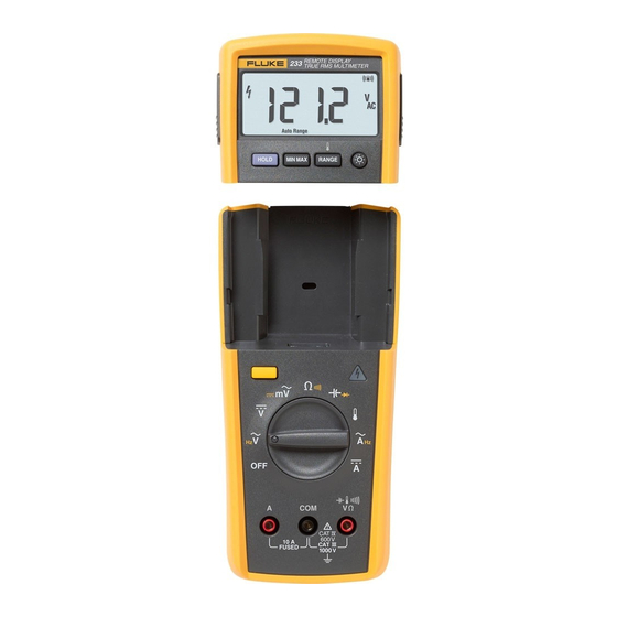
Introduction The Fluke 233 (hereafter the Meter) is a compact and easy to operate tool for electrical and electronic circuit measurements. XWWarning Read "Safety Information" before you use the Meter. How to Contact Fluke Use one of the telephone numbers below to speak with a... -
Page 12: Safety Information
Users Manual Safety Information Warnings and Cautions The Meter complies with: XWWarning To prevent possible electrical shock or ISA-82.02.01 personal injury, follow these guidelines: CAN/CSA C22.2 No. 61010-1-04 Use this Meter only as specified in this ANSI/UL 61010-1:2004 manual or the protection can be EN 61010-1:2001 compromised. - Page 13 True-rms Remote Display Digital Multimeter Safety Information Remove the test leads from the Meter For current measurements, connect the before the battery door on the Meter Meter to the circuit after you remove base is opened. circuit power. Always put the Meter in series with the circuit.
- Page 14 Users Manual Use only specified 1.5-V AA batteries WCaution (three in the Meter base and two in the To prevent damage to the Meter or to the display), correctly installed, for Meter equipment under test, follow these power. guidelines: Comply with local and national safety Disconnect circuit power and discharge requirements when in hazardous all high-voltage capacitors before you do...
-
Page 15: Radio Frequency Data
Changes or modifications to the wireless 2.4 equipment off and on, the user is encouraged to try to GHz radio not expressly approved by Fluke correct the interference by one or more of the measures Corporation could void the user’s authority to that follow: operate the equipment. -
Page 16: Hazardous Voltage
Users Manual Hazardous Voltage When the Meter senses a voltage 30 V or a voltage overload (), the symbol is shown on the display and the red high-voltage LED on the Meter base illuminates to tell you a hazardous voltage is at the Meter input. For frequency measurements >1 kHz, the ... - Page 17 Do not discard this product as unsorted municipal waste. Go to the Fluke website Diode for recycling data. Examined and licensed by TÜV Product ®...
-
Page 18: Features
Users Manual Features See Tables 3 through 4 for a list of Meter features with a short feature description. Table 2. Display meter remote Auto RangeManual Range gcc101.eps Symbol Indication MIN MAX AVG mode on. MAX MIN AVG Maximum, minimum, or average measurement shown. Display hold on. - Page 19 True-rms Remote Display Digital Multimeter Features Table 2. Display (cont.) Symbol Indication Radio connection indicator. C, F degrees Celsius, degrees Fahrenheit amperes (amps) volts, millivolts V, mV F, nF microfarad, nanofarad DC AC Direct current or alternating current. , M , k ohm, megohm, kilohm hertz, kilohertz Hz, kHz...
- Page 20 Users Manual Table 3. Inputs gcc110.eps Terminal Description Input for 0 A to 10.00 A current measurements. Common terminal for all measurements. Input for voltage, continuity, resistance, diode, capacitance, temperature, and frequency measurements.
- Page 21 True-rms Remote Display Digital Multimeter Features Table 4. Function Switch Positions Switch Description Position AC voltage from 0.06 to 1000 V. Frequency from 5 Hz to 50 kHz. Hz (button) DC voltage from 0.001 V to 1000 V. ...
-
Page 22: Error Messages
Users Manual Error Messages Table 5 contains possible error messages and the steps to clear the error. Table 5. Error Messages Error Messages Display-module batteries must be replaced before the Meter will operate. Meter-base batteries must be replaced before the Meter will operate. ... -
Page 23: Battery Saver™(Sleep Mode)
True-rms Remote Display Digital Multimeter Battery Saver™(Sleep Mode) To pause MIN MAX AVG record mode, push . Battery Saver™(Sleep Mode) is shown. A pause does not erase recorded The Meter powers-down (Sleep mode) if there is no MIN MAX AVG measurements. function change, range change, or button push for 20 minutes. -
Page 24: Display Hold
Users Manual Display Hold In the Manual Range mode, push to increment the range. After the highest range, the range of the XW Warning Meter is set to the lowest range. To prevent electrical shock, when Display Note HOLD is on, disable Display HOLD to You cannot manually change the range in the measure the voltage that is possibly different MIN MAX AVG or Display HOLD modes. -
Page 25: Backlight
True-rms Remote Display Digital Multimeter Backlight Backlight Push to toggle the backlight on and off. The backlight automatically extinguishes after 40 seconds. To disable backlight auto-off, hold down while turning the Meter Power-Up Options Hold a button down while the function switch is moved from the OFF position to set a power-up option. -
Page 26: How To Make Measurements
Users Manual How to Make Measurements AC Voltage The sections that follow tell how to make measurements with the Meter. Switch Box To connect the test leads to the circuit or device, connect the common (COM) test lead first. To remove the test leads, remove the common test lead last. -
Page 27: Resistance Measurements
True-rms Remote Display Digital Multimeter How to Make Measurements Resistance Measurements current in the next higher range. If the value is higher, use the higher value. Refer to the Input Parameters WCaution table in the specifications section for typical short- To prevent possible damage to the Meter or to circuit currents. - Page 28 Users Manual In-Circuit Resistance Measurements Isolating a Potentiometer Circuit Power Disconnect Isolating a Resistor Disconnect gcc106.eps Figure 2. Resistance Measurements...
-
Page 29: Temperature Measurements
True-rms Remote Display Digital Multimeter How to Make Measurements Temperature Measurements Continuity Tests The Meter measures the temperature of a type-K WCaution thermocouple (included). Choose between degrees To prevent possible damage to the Meter or Celsius ( C) or degrees Fahrenheit ( F) by pushing the equipment under test, disconnect power and discharge all high-voltage capacitors W Caution... - Page 30 Users Manual For in-circuit tests, turn circuit power off. (closed) (open) Activates continuity beeper gcc103.eps Figure 3. Continuity Tests...
-
Page 31: Diode Tests
True-rms Remote Display Digital Multimeter How to Make Measurements Diode Tests WCaution To prevent possible damage to the Meter or to the equipment under test, disconnect power and discharge all high-voltage capacitors before a diode test. Do a diode test on diodes, transistors, silicon controlled rectifiers (SCRs), and other semiconductor devices. - Page 32 Users Manual Reverse Bias Forward Bias Typical Reading Single Beep Shorted Open Bad Diode gcc109.eps Figure 4. Diode Test...
-
Page 33: Capacitance Measurements
True-rms Remote Display Digital Multimeter How to Make Measurements Capacitance Measurements WCaution To prevent possible damage to the Meter or Select to the equipment under test, disconnect Capacitance power and discharge all high-voltage capacitors before capacitance measurements. Use the dc voltage function to make sure that the capacitor is discharged. -
Page 34: Ac And Dc Current Measurements
Users Manual AC and DC Current Measurements The current ranges are 6.000 A, and 10.00 A. AC current is shown as an rms value. XWWarning To measure current (see Figure 6): To prevent possible electrical shock or personal injury, do not make an in-circuit Remove power from the circuit. - Page 35 True-rms Remote Display Digital Multimeter How to Make Measurements Total Current to Circuit Circuit Power: OFF to connect meter. ON for measurement. OFF to disconnect meter. Current Through One Component gcc107.eps Figure 6. Current Measurements...
-
Page 36: Frequency Measurements
Users Manual Frequency Measurements Remote Operation A frequency measurement is a count of the number of The Meter uses low-power 802.15.4 wireless technology times an ac voltage or current signal crosses a threshold to allow the display module to operate in a different point each second. -
Page 37: Remove The Display Module
True-rms Remote Display Digital Multimeter Remote Operation Remove the Display Module To remove the display module (see Figure 7): Push in on the latches on the sides of the display module. Pull the display module off of the top end of the Meter base. -
Page 38: Dock The Display Module With The Meter Base
Users Manual If the radios in the Meter base and display module do not connect, flashes in the display. Dock the display module with the Meter base and turn the Meter off and then on. When the Meter is turned on, the red high- voltage LED on the Meter base flashes. -
Page 39: Maintenance
True-rms Remote Display Digital Multimeter Maintenance Maintenance Battery Replacement XWWarning XWWarning To prevent incorrect measurements, possible To prevent a possible electrical shock or electrical shock, or personal injury, replace personal injury, have an approved technician the battery when the battery indicator () repair the Meter. - Page 40 Users Manual gcc112.eps Figure 9. Meter Base Battery Replacement...
- Page 41 True-rms Remote Display Digital Multimeter Maintenance To replace the batteries in the Meter base: Turn the Meter off and remove all test leads. Lift the tilt stand up as shown in Figure 9. Turn the battery-door latch with a standard screwdriver until the unlocked symbol () aligns with the arrow.
- Page 42 Users Manual To replace the batteries in the display module: Remove the display module from the Meter base. See the “Remove the Display” section. Remove the battery door of the display module as shown in Figure 10. Remove the two AA batteries and replace them with new ones.
-
Page 43: Fuse Test
True-rms Remote Display Digital Multimeter Maintenance Fuse Test To do a fuse test: Good fuse: 0.0 Ω to 0.5 Ω Set the function switch to . Replace fuse: OL Connect a test lead to the jack as shown in Figure 11. -
Page 44: Fuse Replacement
Remove the fuse from its holder and replace it with an 11 A, 1000 V, FAST fuse with a minimum interrupt rating of 17,000 A. Use only Fluke PN 803293. To re-assemble the Meter, do the steps above in the opposite sequence. -
Page 45: Service And Parts
Alligator Clip, Red Test Lead Set TL75 Integrated DMM Temperature Probe 80BK-A 233 Users Manual CD 3465353 233 Getting Started Manual 3465366 W To ensure safety, use exact replacement only. [1] Contact your local Fluke service center for display replacement. - Page 46 Users Manual Fuse, TL75 233 Display 11A, 1000 V, Fast Test Lead Set Battery AA 1.5 V Battery Door Display Module Battery Door AC72 Meter Base Alligator Clips Getting Started Manual Users Manual CD 80BK-A Integrated DMM Temperature Probe gcc116.eps Figure 13.
- Page 47 Industrial Test Lead Set AC285 SureGrip™ Alligator Clips AC87 Heavy Duty Bus Bar Clip Set i400s AC Current Clamp (requires PM9081 adapter) PM9081 Dual Banana Plug (male) to Female BNC Adapter Fluke accessories are available from an approved Fluke distributor.
-
Page 48: General Specifications
Users Manual General Specifications Maximum voltage between any terminal and earth ground ........... 1000 V rms W Fuse for A inputs ............. 11 A, 1000 V 17000A interrupt rating Fuse Display ................6000 counts, updates 4/sec (Frequency: 9,999 counts, Capacitance: 1,000 counts) Altitude Operating .............. -
Page 49: Detailed Specifications
True-rms Remote Display Digital Multimeter Detailed Specifications Weight ................604 g (1.3 lbs) Safety Compliance ............Complies with ANSI/ISA S82.01-2004, CSA 22.2 No. 61010-1-04 to 1000 V Measurement Category III and 600 V Measurement Category IV. Certifications ..............CSA, TÜV (EN61010), P, ; (N10140),VDE, GOST Detailed Specifications For all detailed specifications: Accuracy is specified for 1 yr after calibration, at operating temperatures of 18 C to 28 C, with relative humidity at 0 % to 90 %. -
Page 50: Dc Voltage, Conductance, And Resistance
Users Manual DC Voltage, Conductance, and Resistance Function Range Resolution Accuracy mV dc 600.0 mV 0.1 mV 6.000 V 0.001 V (0.25 % + 2) 60.00 V 0.01 V V dc 600.0 V 0.1 V 1000 V 600.0 (0.9 % + 2) 6.000 k 0.001 k 60.00 k... -
Page 51: Ac Current
True-rms Remote Display Digital Multimeter Detailed Specifications AC Current Accuracy Function Range Resolution (45 – 500 Hz) [1,2,3] 6.000 A 0.001 A A ac (1.5 % + 3) 10.00 A 0.01 A All ranges are specified from 5 % of range to 100 % of range. Crest factor of 3 at 4000 counts, decreasing linearly to 1.5 at full scale. -
Page 52: Capacitance
Users Manual Capacitance Range Resolution Accuracy 1000 nF 1 nF 10.00 F 0.01 F (1.9 % + 2) 100.0 F 0.1 F 9999 F >1000 F: 5 % + 20 Diode Range Resolution Accuracy 2.000 V 0.001 V (0.9 % + 2) -
Page 53: Frequency
True-rms Remote Display Digital Multimeter Detailed Specifications Frequency AC coupled, 5 Hz to 50 kHz, for V ac; dc coupled, 45 Hz to 5 kHz for A ac switch position. Range Resolution Accuracy 99.99 Hz 0.01 Hz 999.9 Hz 0.1 Hz (0.1 % + 2) 9.999 kHz 0.001 kHz... -
Page 54: Input Characteristics
Users Manual Input Characteristics Input Common Mode Overload Function Impedance Rejection Ratio Normal Mode Rejection Protection (nominal) (1 k unbalance) > 100 dB at dc, 50 Hz 1100 V rms >10 M <100 pF > 60 dB at 50 Hz or 60 Hz or 60 Hz 1100 V rms >5 M <...
Need help?
Do you have a question about the 233 and is the answer not in the manual?
Questions and answers