Table of Contents
Advertisement
Quick Links
PZ265E
PL0xx/PDxxx Piezo Actuator
User Manual
Version: 1.0.0
PI Ceramic GmbH, Lindenstrasse, 07589 Lederhose, Germany
Phone +49 36604 882-0, Fax +49 36604 882-4109, Email info@piceramic.com, www.piceramic.com
Date: 09.12.2016
This document describes the following products:
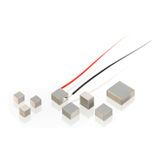
PL022 / PL033 / PL055 / PL088
PICMA® Chip miniature multilayer piezo
actuators
PD161
Round PICMA® Chip miniature multilayer piezo
actuators
PD050 / PD080 / PD120 / PD150 / PD160
Round PICMA® Chip miniature multilayer piezo
actuators with inner hole
Advertisement
Table of Contents

Related Manuals for PI PZ265E


Summary of Contents for PI PZ265E
- Page 1 Round PICMA® Chip miniature multilayer piezo actuators PD050 / PD080 / PD120 / PD150 / PD160 Round PICMA® Chip miniature multilayer piezo actuators with inner hole PI Ceramic GmbH, Lindenstrasse, 07589 Lederhose, Germany Phone +49 36604 882-0, Fax +49 36604 882-4109, Email info@piceramic.com, www.piceramic.com...
- Page 2 © 2016 PI Ceramic GmbH, Lederhose, Germany. The text, photographs and drawings in this manual are protected by copyright. With regard thereto, PI Ceramic GmbH retains all the rights. Use of said text, photographs and drawings is permitted only in part and only upon citation of the source.
-
Page 3: Table Of Contents
Contents About this Document Objective and Target Audience of this User Manual..........1 Validity for Custom Products ..................1 Symbols and Typographic Conventions..............2 Figures ........................2 Other Applicable Documents ..................3 Downloading Manuals ....................3 Safety Intended Use ......................5 General Safety Instructions .................. - Page 4 Start-Up and Operation General Notes on Start-Up and Operation ............... 31 Determining the Operating Parameters ..............35 6.2.1 Overview of Limiting Factors ............... 36 6.2.2 Calculating the Effective Mass ..............37 6.2.3 Calculating the Maximum Operating Frequency of the Loaded Piezo Actuator .......................
-
Page 5: About This Document
The product line is stated on the delivery note of the custom product. The properties of custom products may differ from those stated in this manual. The latest versions of the user manuals are available for download (p. 3) on our website. PL0xx/PDxxx Piezo Actuator PZ265E Version: 1.0.0... -
Page 6: Symbols And Typographic Conventions
RS-232 interface) Figures For better understandability, the colors, proportions, and degree of detail in illustrations can deviate from the actual circumstances. Photographic illustrations may also differ and must not be seen as guaranteed properties. Version: 1.0.0 PZ265E PL0xx/PDxxx Piezo Actuator... -
Page 7: Other Applicable Documents
For products that are supplied with software (CD in the scope of delivery), access to the manuals is protected by a password. Protected manuals are only displayed on the website after entering the password. The password is included on the CD of the product. PL0xx/PDxxx Piezo Actuator PZ265E Version: 1.0.0... - Page 8 4. Find the user name and the password in the section "User login for software download" in the Release News. Downloading manuals 1. Open the website www.pi.ws. 2. If access to the manuals is protected by a password: a) Click Login.
-
Page 9: Safety
For operation of the PL0xx/PDxxx, suitable electronics that provide the required operating voltages are required. The electronics are not included in the scope of delivery of the PL0xx/PDxxx. We recommend the use of suitable electronics (p. 12) from PI. General Safety Instructions The PL0xx/PDxxx is built according to state-of-the-art technology and recognized safety standards. - Page 10 Prevent torques and lateral forces on the PL0xx/PDxxx. Do not use metal tools during installation. Do not exceed the maximum permissible stress and load capacities according to the specifications (p. 49). Version: 1.0.0 PZ265E PL0xx/PDxxx Piezo Actuator...
-
Page 11: Organizational Measures
Only install and operate the PL0xx/PDxxx after you have read and understood this user manual. Personnel qualification The PL0xx/PDxxx may only be installed, started up, operated, maintained, and cleaned by authorized and appropriately qualified personnel. PL0xx/PDxxx Piezo Actuator PZ265E Version: 1.0.0... -
Page 13: Product Description
PICMA® Chip miniature piezo actuator, 2.2 µm travel range, 10 mm × 10 mm × 2 mm, stranded wires Round PICMA® Chip miniature multilayer piezo actuators Model Description PD161.31 Round PICMA® Chip miniature piezo actuator, 2.3 µm travel range, OD 16 mm × TH 2.5 mm, stranded wires PL0xx/PDxxx Piezo Actuator PZ265E Version: 1.0.0... -
Page 14: Product View
The positive electrode does not cover the entire side surface. Negative electrode: Connection for ground (-) The negative electrode covers the entire side surface. Ceramic end surface (passive PZT) Arrow: Expansion direction of the piezo actuator when a positive voltage is applied Version: 1.0.0 PZ265E PL0xx/PDxxx Piezo Actuator... -
Page 15: Product Labeling
The product number of custom products consists of nine digits (without identification of the model). 16CEP0653128979 Batch number (example), individual for each PL0xx/PDxxx Manufacturer's logo 1 Stueck Quantity Country of origin: Germany Country of origin WWW.PICERAMIC.COM Manufacturer's address (website) PL0xx/PDxxx Piezo Actuator PZ265E Version: 1.0.0... -
Page 16: Scope Of Delivery
The P-890.xx cable is for connecting the PL0xx/PDxxx to a low-voltage piezo amplifier with a single-pole LEMO socket. The cable is soldered on the actuator side. Connector: FFS.00.250.CTCE24 Cable: RG 178 (Teflon) To order, contact our customer service department (p. 47). Version: 1.0.0 PZ265E PL0xx/PDxxx Piezo Actuator... -
Page 17: Technical Features
The ceramic insulation layer protects the monolithic piezoceramic block against humidity or failure due to increased leakage current. In this way, an especially high reliability is achieved even under extreme ambient conditions. PL0xx/PDxxx Piezo Actuator PZ265E Version: 1.0.0... -
Page 19: Unpacking
2. Compare the contents with the items listed in the contract and the packing list. 3. Inspect the contents for signs of damage. If there is any sign of damage or missing parts, contact PI Ceramic immediately. 4. Keep all packaging materials in case the product needs to be returned. -
Page 21: Installation
When handling the piezo actuator, wear powder-free nitrile or latex gloves. Keep the piezo actuator short-circuited (p. 41) when it is not connected to the electronics. Do not disassemble the piezo actuator. PL0xx/PDxxx Piezo Actuator PZ265E Version: 1.0.0... - Page 22 Damage to the piezo actuator due to excessive preloading! Excessive preloading can mechanically depolarize the piezo actuator. Depolarization damages the piezo actuator. Only apply preloads that are just as high as necessary. Do not exceed the maximum preload (p. 52). Version: 1.0.0 PZ265E PL0xx/PDxxx Piezo Actuator...
- Page 23 Ground loops can occur when the piezo actuator is installed in a housing that is grounded via the shield of the connecting cable of the piezo actuator as well as a separate protective earth conductor. If a ground loop occurs, contact our customer service department (p. 47). PL0xx/PDxxx Piezo Actuator PZ265E Version: 1.0.0...
- Page 24 (p. 27) mechanically in order to avoid tensile stress. The following figures are to help you avoid mounting errors. Figure 3: Prevention of lateral forces and torques Figure 4: Prevention of torques Figure 5: Prevention of tensile stresses by means of a mechanical preload Version: 1.0.0 PZ265E PL0xx/PDxxx Piezo Actuator...
- Page 25 Full-area contact of the piezo actuator Figure 8: Proper dimensioning of the end pieces in the case of point contact (1: Tensile stresses) Figure 9: Mechanical or thermal loads electrically charge the piezo actuator. Mount only when short- circuited. PL0xx/PDxxx Piezo Actuator PZ265E Version: 1.0.0...
-
Page 26: Connecting A Piezo Actuator With Stranded Wires (Only Models Without Stranded Wires)
Use a black stranded wire for ground (-). Requirements You have read and understood the general notes on installation (p. 17). The PL0xx/PDxxx is discharged (p. 40) and short-circuited (p. 41). Version: 1.0.0 PZ265E PL0xx/PDxxx Piezo Actuator... - Page 27 Solder connection [2] of stranded wire [1] and electrode [3] 6. Repeat steps 1 to 5 for the second stranded wire. 7. Remove flux residue according to the instructions in the section "Cleaning the PL0xx/PDxxx" (p. 43). PL0xx/PDxxx Piezo Actuator PZ265E Version: 1.0.0...
-
Page 28: Gluing Stranded Wires To A Piezo Actuator (Only Models Without Stranded Wires)
When gluing the stranded wires to the electrodes, make sure that the adhesive does not spread beyond the glueing point at any time. INFORMATION For optimum electrical contacting, it is recommended to use the following materials: Silver-plated stranded wires Electrically conductive, silver-filled epoxy resin adhesive Version: 1.0.0 PZ265E PL0xx/PDxxx Piezo Actuator... - Page 29 Hold the stranded wire in the desired orientation on the adhesive point and fix the stranded wire. 4. Repeat steps 2 and 3 for the second stranded wire. 5. Wait until the adhesive has completely hardened. PL0xx/PDxxx Piezo Actuator PZ265E Version: 1.0.0...
-
Page 30: Mounting The Pl0Xx/Pdxxx
During the hardening process, maintain the operating temperature range (p. 53) specified for the piezo actuator. − Observe the temperature expansion coefficients of the materials involved. 2. Press the piezo actuator until the adhesive has hardened. Version: 1.0.0 PZ265E PL0xx/PDxxx Piezo Actuator... -
Page 31: Applying A Preload
The resonant frequency (p. 49) of the preload spring exceeds that of the piezo actuator. Applying a preload Apply the preload near the axis within the core cross section of the piezo actuator. PL0xx/PDxxx Piezo Actuator PZ265E Version: 1.0.0... -
Page 32: Applying The Load
If a point load is applied to the end piece of the piezo actuator: Dimension the end piece so that its thickness corresponds to half the cross-sectional dimension in order to prevent tensile stresses on the piezo actuator. Version: 1.0.0 PZ265E PL0xx/PDxxx Piezo Actuator... -
Page 33: Connecting The Pl0Xx/Pdxxx To The Electronics
On the LEMO connector (right): Connector housing Cable shield LEMO LEMO connector, single-pole Requirements You have read and understood the general notes on installation (p. 17). You have read and understood the user manual of the electronics used. PL0xx/PDxxx Piezo Actuator PZ265E Version: 1.0.0... - Page 34 4. Solder the black stranded wire of the PL0xx/PDxxx to the cable shield of the coaxial cable. 5. Insulate the soldered cable connections in a suitable manner. 6. Connect the connector of the PL0xx/PDxxx to the corresponding connection on the electronics. Version: 1.0.0 PZ265E PL0xx/PDxxx Piezo Actuator...
-
Page 35: Start-Up And Operation
Do not remove the protective earth conductor during operation. If the protective earth conductor has to be temporarily removed (e.g., for modifications), reconnect the overall system to the protective earth conductor before starting it up again. PL0xx/PDxxx Piezo Actuator PZ265E Version: 1.0.0... - Page 36 During dynamic operation, dynamic forces can occur that cancel the preload of the piezo actuator. Operation without a preload can destroy the actuator. Do not exceed the maximum compressive/tensile stress capacity (p. 52). Observe the notes in "Determining the Operating Parameters" (p. 35). Version: 1.0.0 PZ265E PL0xx/PDxxx Piezo Actuator...
- Page 37 Do not pull the connecting cable of the piezo actuator out of the electronics during operation. If the connecting cable of the piezo actuator is accidentally pulled out of the electronics during operation: Switch off the electronics before you reconnect the piezo actuator. PL0xx/PDxxx Piezo Actuator PZ265E Version: 1.0.0...
- Page 38 Conditions and Classifications" (p. 53), "Maximum Ratings" (p. 51), and "Determining the Operating Parameters" (p. 35). Cool the piezo actuator. Do not use liquids for cooling. If liquid cooling is to be used, contact our customer service department (p. 47). Version: 1.0.0 PZ265E PL0xx/PDxxx Piezo Actuator...
-
Page 39: Determining The Operating Parameters
For determination of the the operating parameters, it is assumed that the piezo actuator is clamped on one side. If you require operating parameters for unclamped operation of the piezo actuator, contact our customer service department (p. 47). PL0xx/PDxxx Piezo Actuator PZ265E Version: 1.0.0... -
Page 40: Overview Of Limiting Factors
The output current of the electronics does not exceed the maximum power consumption of the piezo actuator. See "Maximum Ratings" (p. 51). − The control signal of the electronics does not have steep edges. See "General Notes on Start-Up and Operation" (p. 31). Version: 1.0.0 PZ265E PL0xx/PDxxx Piezo Actuator... -
Page 41: Calculating The Effective Mass
For the maximum permissible operating frequency without cooling, see column B of the table in "Maximum Ratings" (p. 51). PL0xx/PDxxx Piezo Actuator PZ265E Version: 1.0.0... -
Page 42: Calculating The Forces That Occur During Dynamic Operation
M [kg], see also "Calculating the Effective Mass" (p. 37) ΔL = Displacement in the application (peak-to-peak) [m] f = Frequency [Hz] Example: The dynamic forces at 1000 Hz, 2 μm displacement (peak-to-peak) and 1 kg effective mass are approximately ±40 N. Version: 1.0.0 PZ265E PL0xx/PDxxx Piezo Actuator... -
Page 43: Calculating The Power Requirement For Sinusoidal Operation
You have read and understood the user manual of the electronics used. Operating the PL0xx/PDxxx For starting up and operating the PL0xx/PDxxx, follow the instructions in the manual of the electronics (p. 3) used. PL0xx/PDxxx Piezo Actuator PZ265E Version: 1.0.0... -
Page 44: Discharging The Pl0Xx/Pdxxx
3. Short-circuit the electrodes of the PL0xx/PDxxx for at least a few seconds using a 10 kΩ discharge resistor. If the PL0xx/PDxxx has a connector: Connect the voltage connector of the PL0xx/PDxxx to the switched-off PI electronics, which has an internal discharge resistor, for at least a few seconds. Version: 1.0.0... -
Page 45: Short-Circuiting The Pl0Xx/Pdxxx
If no bare stranded wires are accessible on the PL0xx/PDxxx: a) If necessary, let the PL0xx/PDxxx cool down. b) Affix a suitable, conductive aid on the discharged piezo actuator that does not scratch the surface of the piezo actuator (e.g., conductive rubber). PL0xx/PDxxx Piezo Actuator PZ265E Version: 1.0.0... -
Page 47: Maintenance
Do not use acetone and do not use water for cleaning. When necessary, clean the surfaces of the PL0xx/PDxxx with a lint-free cloth that is slightly dampened with a mild cleanser (e.g., isopropanol or ethanol). PL0xx/PDxxx Piezo Actuator PZ265E Version: 1.0.0... - Page 48 Only use isopropanol or ethanol as cleaning fluid. − Observe a cleaning time of 5 minutes. After cleaning, dry the PL0xx/PDxxx completely in a drying cabinet (recommended duration: 30 minutes at 40 °C). Version: 1.0.0 PZ265E PL0xx/PDxxx Piezo Actuator...
-
Page 49: Troubleshooting
If the problem that occurred with your system is not listed in the table above or cannot be solved as described, contact our customer service department (p. 47). PL0xx/PDxxx Piezo Actuator PZ265E Version: 1.0.0... -
Page 51: Customer Service
9 Customer Service Customer Service You can contact PI Ceramic by telephone under +49 36604 882-0 or by email at the following address: For general questions or for orders: info@piceramic.com In the case of technical problems or faults: ... -
Page 53: Technical Data
**** Measured at 1 V , unloaded, unclamped. The value is halved for unilateral clamping. Depending on the installation situation, the lateral resonant frequencies can be lower than the axial resonant frequencies. Ask about custom designs! PL0xx/PDxxx Piezo Actuator PZ265E Version: 1.0.0... - Page 54 **** Measured at 1 V , unloaded, unclamped. The value is halved for unilateral clamping. Depending on the installation situation, the lateral resonant frequencies can be lower than the axial resonant frequencies. Ask about custom designs! Version: 1.0.0 PZ265E PL0xx/PDxxx Piezo Actuator...
-
Page 55: Maximum Ratings
–20 V to 100 V 83.3 kHz 100 Hz 0.6 W PD120.3x –20 V to 100 V 83.3 kHz 50 Hz 0.9 W PD150.3x –20 V to 100 V 100 kHz 50 Hz 1.0 W PL0xx/PDxxx Piezo Actuator PZ265E Version: 1.0.0... -
Page 56: Compressive/Tensile Stress Capacity And Preload
* 1 MPa corresponds to a pressure of 1 N per square millimeter of the base area of the piezo actuator. Dimensions see data table (p. 49). ** Depends on the strength of the glued connections (p. 26) Version: 1.0.0 PZ265E PL0xx/PDxxx Piezo Actuator... -
Page 57: Ambient Conditions And Classifications
(p. 47). Observe the information on service life, which can be found here: − Section "General Notes on Start-Up and Operation" (p. 31) − Internet site of PI Ceramic (www.piceramic.com/piezo- technologie/picma.html) Operating temperature –40 °C to 150 °C Storage temperature –40 °C to 80 °C... -
Page 58: Dimensions
Length A Length B Height TH Unit PL022.3x 2 (±0.10) 2 (±0.10) 2 (±0.10) PL033.3x 3 (±0.10) 3 (±0.10) 2 (±0.10) PL055.3x 5 (±0.15) 5 (±0.15) 2 (±0.10) PL088.3x 10 (±0.20) 10 (±0.20) 2 (±0.10) Version: 1.0.0 PZ265E PL0xx/PDxxx Piezo Actuator... - Page 59 PD080.3x 8 (±0.3) 4.5 (±0.15) 2.5 (±0.05) PD120.3x 12 (±0.4) 6 (±0.2) 2.5 (±0.05) PD150.3x 15 (±0.3) 9 (±0.15) 2 (±0.05) PD160.3x 16 (±0.5) 8 (±0.25) 2.5 (±0.05) PD161.3x 16 (±0.5) – 2.5 (±0.05) PL0xx/PDxxx Piezo Actuator PZ265E Version: 1.0.0...
-
Page 61: Disposal
PI products made available on the market after August 13, 2005, without charge. Any product from PI Ceramic that is to be disposed of can be sent free of shipping costs to the following address: PI Ceramic GmbH... -
Page 63: Eu Declaration Of Conformity
RoHS: EN 50581 If an electrical operating device is designed to be integrated into another electrical operating device: The operator is responsible for standards compliant integration of the electrical device into the overall system. PL0xx/PDxxx Piezo Actuator PZ265E Version: 1.0.0...
Need help?
Do you have a question about the PZ265E and is the answer not in the manual?
Questions and answers