Table of Contents
Advertisement
Quick Links
PZ266E
P-88x.x5 Piezo Actuator
User Manual
Version: 1.1.0
PI Ceramic GmbH, Lindenstrasse, 07589 Lederhose, Germany
Phone +49 36604 882-0, Fax +49 36604 882-4109, Email info@piceramic.com, www.piceramic.com
Date: 27.09.2021
This document describes the following products:
P-885.55
Encapsulated PICMA® piezo actuator, 14 µm
travel range, OD 11.2 mm × L 22.5 mm,
stranded wires
P-885.95
Encapsulated PICMA® piezo actuator, 30 µm
travel range, OD 11.2 mm × L 40.5 mm,
stranded wires
P-888.55
Encapsulated PICMA® piezo actuator, 14 µm
travel range, OD 18.6 mm × L 22.5 mm,
stranded wires
Advertisement
Table of Contents

Related Manuals for PI P-88 5 Series


Summary of Contents for PI P-88 5 Series
- Page 1 OD 11.2 mm × L 40.5 mm, stranded wires P-888.55 Encapsulated PICMA® piezo actuator, 14 µm travel range, OD 18.6 mm × L 22.5 mm, stranded wires PI Ceramic GmbH, Lindenstrasse, 07589 Lederhose, Germany Phone +49 36604 882-0, Fax +49 36604 882-4109, Email info@piceramic.com, www.piceramic.com...
- Page 2 © 2021 PI Ceramic GmbH, Lederhose, Germany. The text, photographs and drawings in this manual are protected by copyright. With regard thereto, PI Ceramic GmbH retains all the rights. Use of said text, photographs and drawings is permitted only in part and only upon citation of the source.
-
Page 3: Table Of Contents
Contents About this Document Objective and Target Audience of this User Manual..........1 Validity for Custom Products ..................1 Symbols and Typographic Conventions..............1 Figures ........................2 Other Applicable Documents ..................2 Downloading Manuals ....................3 Safety Intended Use ......................5 General Safety Instructions .................. - Page 4 6.2.5 Calculating the Power Requirement for Sinusoidal Operation ....29 Operating the P-88x.x5 ..................... 29 Discharging the P-88x.x5 ..................30 Short-Circuiting the P-88x.x5 ..................31 Maintenance General Notes on Maintenance ................33 Cleaning the P-88x.x5 ....................33 Troubleshooting Customer Service Technical Data 10.1 Specifications ......................
-
Page 5: About This Document
1 About this Document About this Document In this Chapter Objective and Target Audience of this User Manual ..............1 Validity for Custom Products ......................1 Symbols and Typographic Conventions ..................1 Figures ............................2 Other Applicable Documents ......................2 Downloading Manuals ........................ -
Page 6: Figures
Other Applicable Documents The devices and software tools from PI mentioned in this documentation are described in separate manuals. The latest versions of the user manuals are available for download (p. 3) on our website. -
Page 7: Downloading Manuals
If a manual is missing or problems occur with downloading: Contact our customer service department (p. 37). Downloading Manuals 1. Open the website www.pi.ws. 2. Search the website for the product number (e.g., P-885) or the product family (e.g., PICMA® Stack). -
Page 9: Safety
For operation of the P-88x.x5, suitable electronics that provide the required operating voltages are required. The electronics are not included in the scope of delivery of the P-88x.x5. We recommend the use of suitable electronics (p. 11) from PI. General Safety Instructions The P-88x.x5 is built according to state-of-the-art technology and recognized safety standards. - Page 10 If the piezo actuator is to be used in a vacuum, attention must be paid to the corresponding cleanliness. At PI, all parts are cleaned before assembly. During assembly and calibration, powder-free gloves are worn. Afterwards, the piezo actuator is wiped clean once again and then shrink-wrapped in vacuum-compatible film.
-
Page 11: Organizational Measures
2 Safety Organizational Measures User manual Always keep this user manual together with the P-88x.x5. The latest versions of the user manuals are available for download (p. 3) on our website. Add all information from the manufacturer to the user manual, for example supplements or technical notes. -
Page 13: Product Description
3 Product Description Product Description In this Chapter Model Overview ..........................9 Product View ..........................10 Product Labeling .......................... 10 Scope of Delivery ......................... 11 Suitable Electronics ........................11 Accessories ........................... 12 Technical Features ........................12 Model Overview Encapsulated PICMA® Stack multilayer piezo actuators with inert gas filling Model Description P-885.55... -
Page 14: Product View
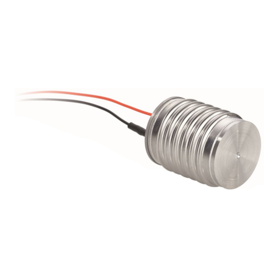
3 Product Product View The figure serves as an example and can differ from your model. Figure 1: Exemplary product view: P-88x.x5 Stainless steel tip Metal bellows Stainless steel base Stranded wire: Red stranded wire: Voltage connection (+) Black stranded wire: Connection for ground (-) Arrow: Expansion direction of the piezo actuator when a positive voltage is applied The tip (1), the metal bellows (2), and the base (3) form the stainless steel housing. -
Page 15: Scope Of Delivery
3 Product Description Labeling Description P-885.55 Product number (example), the digits after the period refer to the model The product number of custom products consists of nine digits (without identification of the model). 16CEP0653128979 Batch number (example), individual for each P-88x.x5 Manufacturer's logo 1 piece Quantity... -
Page 16: Accessories
3 Product Accessories Product number Description P-890.10 Cable for piezo voltage, LEMO connector/open end, 1 m P-890.20 Cable for piezo voltage, LEMO connector/open end, 5 m The P-890.xx cable is for connecting the P-88x.x5 to a low-voltage piezo amplifier. The cable is soldered on the actuator side. -
Page 17: Unpacking
If the piezo actuator is to be used in a vacuum, attention must be paid to the corresponding cleanliness. At PI, all parts are cleaned before assembly. During assembly and calibration, powder-free gloves are worn. Afterwards, the piezo actuator is wiped clean once again and then shrink-wrapped in vacuum-compatible film. -
Page 19: Installation
5 Installation Installation In this Chapter General Notes on Installing ......................15 Mounting the P-88x.x5 ........................ 19 Applying the Load ........................20 Connecting the P-88x.x5 to the Electronics ................. 21 General Notes on Installing CAUTION Dangerous voltage and residual charge in piezo actuators! Temperature changes and compressive stress can induce charges in the P-88x.x5 piezo actuator. - Page 20 5 Installatio NOTICE Short-circuiting due to complete immersion in a liquid! Complete immersion of the P-88x.x5 into a liquid can lead to short-circuiting at the stranded wires. A short-circuit can destroy the P-88x.x5 as well as the electronics connected. Avoid immersing the stranded wires into liquids. If your application requires complete immersion of the P-88x.x5 into a liquid, contact our customer service department (p.
- Page 21 5 Installation NOTICE Heating up of the P-88x.x5 during operation! The heat produced during operation of the P-88x.x5 can affect your application. Install the P-88x.x5 so that your application is not affected by the dissipating heat. INFORMATION Ground loops can occur when the piezo actuator is installed in a housing that is grounded via the shield of the connecting cable of the piezo actuator as well as a separate protective earth conductor.
- Page 22 5 Installatio Figure 4: Prevention of tensile stress by means of a mechanical preload Figure 5: Prevention of an irregular load application (1: Tensile stress) Figure 6: Full-area contact of the piezo actuator Figure 7: Proper dimensioning of the end pieces in the case of point contact (1: Tensile stress) Version: 1.1.0 PZ266E P-88x.x5 Piezo Actuator...
-
Page 23: Mounting The P-88X.x5
5 Installation Figure 8: Mechanical or thermal loads electrically charge the piezo actuator. Mount only when short- circuited. Mounting the P-88x.x5 P-88x.x5 piezo actuators are glued to metal or ceramic surfaces. Requirements You have read and understood the general notes on installation (p. 15). ... -
Page 24: Applying The Load
5 Installatio Applying the Load The P-88x.x5 can be coupled to a load in various ways, depending on the application: Gluing the piezo actuator (p. 19) into the mechanical system to be moved or into a flexure Using a ball tip: ... -
Page 25: Connecting The P-88X.x5 To The Electronics
5 Installation Connecting the P-88x.x5 to the Electronics The P-88x.x5 piezo actuator is connected to a LEMO socket, a terminal, or soldering pins, depending on the electronics. This section describes how the P-88x.x5 piezo actuator is connected with the P-890.xx coaxial cable to electronics with a LEMO coaxial socket. - Page 26 5 Installatio Tools and accessories P-890.xx coaxial cable (p. 12), LEMO to open end (can be ordered separately) Suitable soldering iron Suitable solder Suitable cable tools Connecting the P-88x.x5 to the electronics 1. If necessary, shorten the wire and the cable shield of the coaxial cable to the correct length.
-
Page 27: Starting And Operating
6 Starting and Operating Starting and Operating In this Chapter General Notes on Starting ......................23 Determining the Operating Parameters ..................26 Operating the P-88x.x5 ........................ 29 Discharging the P-88x.x5 ......................30 Short-Circuiting the P-88x.x5 ....................... 31 General Notes on Starting CAUTION Risk of electric shock if the protective earth conductor is not connected! The system into which the piezo actuator is integrated (e.g., housing or surrounding... - Page 28 6 Starting and Operating NOTICE Damage due to steep edges in the control signal! If the actuator does not have a preload, steep edges in the control signal can trigger strong dynamic forces which damage the piezo actuator. Steep edges can occur, for example, when digital wave generators are switched on.
- Page 29 6 Starting and Operating NOTICE Destruction of the piezo actuator due to overheating! During the operation of the piezo actuator, dielectric losses that are converted into heat energy occur in the piezo ceramic due to ferroelectric polarization processes. Heat dissipation to the outside is reduced due to the inert gas filling of the piezo actuator.
-
Page 30: Determining The Operating Parameters
6 Starting and Operating Determining the Operating Parameters 6.2.1 Overview of Limiting Factors Limiting factors for the operation of the piezo actuator: Resonant frequency: The resonant frequency of the piezo actuator serves as a basis for calculating the operating frequency, which must not exceed one third of the resonant frequency. The resonant frequency according to the data table (p. -
Page 31: Calculating The Effective Mass
6 Starting and Operating 6.2.2 Calculating the Effective Mass Figure 10: Calculation of the effective mass of a unilaterally clamped P-88x.x5 without load (left) and with additional load (right). 1. Determine the mass m of your piezo actuator. 2. Determine the additional load M. 3. -
Page 32: Calculating The Forces That Occur During Dynamic Operation
6 Starting and Operating 1. Calculate the resonant frequency of the loaded, unilaterally clamped piezo actuator using the following formula: ' = Resonant frequency of the loaded piezo actuator [Hz] = Resonant frequency of the unloaded piezo actuator [Hz]: The resonant frequency according to the data table (p. -
Page 33: Calculating The Power Requirement For Sinusoidal Operation
6 Starting and Operating 6.2.5 Calculating the Power Requirement for Sinusoidal Operation Calculate the average current requirement for sinusoidal operation using the following formula: Calculate the peak current requirement for sinusoidal operation using the following formula: Variable Description Notes Required average current of the It is essential that the power supply can... -
Page 34: Discharging The P-88X.x5
If the P-88x.x5 has a connector (p. 21): Connect the voltage connector of the P-88x.x5 to the switched off PI electronics, which has an internal discharge resistor, for at least a few seconds. Alternative: Connect a suitable shorting plug with integrated discharge resistor to the voltage connector of the P-88x.x5 for at least a few seconds. -
Page 35: Short-Circuiting The P-88X.x5
6 Starting and Operating Short-Circuiting the P-88x.x5 The P-88x.x5 must be discharged (p. 30) and short-circuited before demounting (e.g., before cleaning and transportation of the P-88x.x5) as well as for modifications. Requirements You have read and understood the general notes on installation (p. 15). ... -
Page 37: Maintenance
7 Maintenance Maintenance In this Chapter General Notes on Maintenance ....................33 Cleaning the P-88x.x5 ........................33 General Notes on Maintenance The P-88x.x5 is maintenance-free. Cleaning the P-88x.x5 Requirements The P-88x.x5 is discharged (p. 30) and short-circuited (p. 31). ... -
Page 39: Troubleshooting
8 Troubleshooting Troubleshooting Problem Possible causes Solution No or limited motion Cable not connected Check the cable connections. correctly Excessive load Do not exceed the maximum compressive/tensile stress capacity (p. 41). Piezo actuator is Contact our customer service depolarized due to department (p. -
Page 41: Customer Service
9 Customer Service Customer Service You can contact PI Ceramic by telephone under +49 36604 882-0 or by email at the following address: For general questions or for orders: info@piceramic.com In the case of technical problems or faults: ... -
Page 43: Technical Data
10 Technical Data Technical Data In this Chapter Specifications ..........................39 Dimensions ..........................42 Subject to change. You can find the latest product specifications on the product web page at www.pi.ws (https://www.pi.ws). 10.1 Specifications 10.1.1 Data Table P-885.55 P-885.95 P-888.55 Unit Dimensions OD ×... -
Page 44: Maximum Ratings
10 Technical Data Operating temperature range: -40 to 150 °C. The operating temperature range does not apply to dynamic operation. If your application involves dynamic operation, contact our customer service department (p. 37). 10.1.2 Maximum Ratings P-88x.x5 piezo actuators are designed for the operating data specified in the table below. Additional information on the maximum ratings table Maximum operating frequency without load, without considering thermal aspects, ... -
Page 45: Compressive/Tensile Stress Capacity And Preload
10 Technical Data 10.1.3 Compressive/Tensile Stress Capacity and Preload Piezo ceramic withstands a pressure of up to 250 MPa but starts to depolarize at significantly lower compressive loads. Since stacked piezo actuators are also made of different materials (piezo ceramic, metallic electrodes), the mechanical load capacity does not depend solely on the strength of the ceramic material. -
Page 46: Dimensions
10 Technical Data The P-88x.x5 is intended for installation in devices that fulfil the following classifications: Protection class Degree of protection according to IP20 IEC 60529 10.2 Dimensions Dimensions in mm Figure 11: P-88x.x5: Dimensions P-885.55 6.4 mm 11 mm 10.25 mm 11.2 mm 22.5 mm... -
Page 47: Old Equipment Disposal
Dispose of your old equipment according to international, national, and local rules and regulations. In order to fulfil its responsibility as the product manufacturer, Physik Instrumente (PI) GmbH & Co. KG undertakes environmentally correct disposal of all old PI equipment made available on the market after 13 August 2005 without charge. - Page 49 12 EU Declaration of Conformity EU Declaration of Conformity An EU Declaration of Conformity was issued for the P-88x.x5 in accordance with the following European directives: RoHS Directive The applied standards certifying the conformity are listed below. RoHS: EN 50581 or EN IEC 63000 If an electrical operating device is designed to be integrated into another electrical operating device: The operator is responsible for standards compliant integration of the electrical device into the overall system.
Need help?
Do you have a question about the P-88 5 Series and is the answer not in the manual?
Questions and answers