Table of Contents
Advertisement
Advertisement
Table of Contents

Related Manuals for Lister Petter K1 64


Summary of Contents for Lister Petter K1 64
- Page 1 K Series Operators' Handbook K1 64, K1 72 Engines P027-10504, Issue 2...
- Page 2 Disclaimer The information, specifications, illustrations, instructions and statements contained within this publication are given with Lister Petter's best intentions and are believed to be correct at the time of going to press. Our policy is one of continued development and we reserve the right to amend any technical informa- tion with or without prior notice.
-
Page 3: Table Of Contents
Contents 1. Introduction ..................4 2. Engine Features ................5 3. Safety Information .................6 4. General Information ..............10 5. Operating Instructions ..............11 6. Engine Fluids ................14 7. Engine Servicing ................15 8. Troubleshooting ................22 9. Maintenance Record ..............25 10. -
Page 4: Introduction
Lister Petter CAUTION Distributor or Dealer for further advice and This caution symbol draws attention to technical assistance. -
Page 5: Engine Features
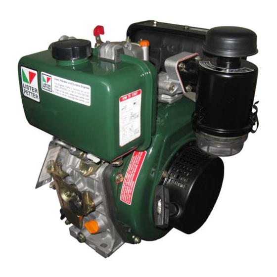
2. Engine Features 2. Engine Features Decompressor lever Exhaust silencer Fuel tank filler Air cleaner Fuel tank Fuel injection pump Fuel tap Speed control assembly Recoil start Oil drain plug Oil filler/dipstick K1 72... -
Page 6: Safety Information
3. Safety Information and Precautions 3. Safety Information and Precautions 3.1 Safety Information, when they occur. g. Remove any build-up of grease, oil or Precautions and Safe Working debris. Practices h. Batteries contain sulphuric acid - if the Follow All Safety Instructions acid has been splashed on the skin, eyes or clothes flush it away with copious a. - Page 7 3. Safety Information and Precautions gency procedures and any necessary the total electrical load required by the personal protection equipment required machine to which it is fitted. while working with hazardous materi- d. Ensure engine wiring cables are: als. Bound together in a loom and adequately supported.
- Page 8 3. Safety Information and Precautions Starter Battery Precautions • Ensure the lifting equipment to be used has the correct capacity to lift the engine WARNING and is designed to give a vertical lift from Sulphuric acid in battery electrolyte is directly above the lifting eyes. poisonous, is strong enough to burn skin, • Check to ensure the engine lifting eyes eat holes in clothing and cause blindness are not damaged and they are secure.
- Page 9 Keep the body and clothing clear of all f. Where possible, disengage the driven moving or hot parts. equipment while starting. f. Never allow any part of the body to come Safety Symbols This section identifies the ISO 8999 symbols currently used by Lister Petter.
-
Page 10: General Information
Net weight Notes: 1. Viewed from output shaft end; 2. Fitted as standard on some models. 4.2 Nomenclature lication, to be carried out. K1 64 - Single cylinder, direct injection, Typical Serial Number naturally aspirated, flywheel fan air cooled 11300123K164C36V diesel engine. K1 72 - Single cylinder, direct injection,... -
Page 11: Operating Instructions
DIN Standards. The maximum ambient operating tem- perature is 40°C (104°F) and if it is desired to run at higher temperatures the local Lister Petter Distributor or Dealer should be consulted. WARNING All engines are dispatched dry, i.e. not containing fuel or oil. - Page 12 5. Operating Instructions 5.3 Electric Key Start 1. Ensure the decompressor lever is in the running position. Figure 5.2.3 Engine Control - Variable Speed 4.Pull the rope handle until you feel ten- sion. Let the rope rewind back into the Figure 5.3.1 Decompressor Lever - Run posi- recoil start;...
-
Page 13: Stopping The Engine
5. Operating Instructions Figure 5.3.3 Start Key 7. If a variable speed control is fitted reduce Figure 5.4.1 Engine Control the speed as required. After the engine has stopped turn the 5.4 Stopping the Engine start key, if fitted, to the 'STOP' position. 2. If a fuel control solenoid is fitted turn the CAUTION start key to the 'STOP' position. Turning the starter key to the 'STOP' po- 3. -
Page 14: Engine Fluids
6. Engine Fluids 6. Engine Fluids 6.1 Oil Specification d. BSMA 100 Class M1 for marine use. The fuel must be a distillate, and not a All subsequent oil changes must be as residual oil or blend. Vaporising oils are not specified in "7.14 Maintenance - Schedule suitable as fuels for these diesel engines. -
Page 15: Engine Servicing
TECTED SKIN TO COME INTO CONTACT in this book. WITH THE INJECTOR SPRAY AS THE FUEL More detailed information can be found MAY ENTER THE BLOOD STREAM WITH in the Workshop Manual or any Lister Petter FATAL RESULTS. Distributor can be consulted. • The engine should receive regular atten- WARNING... -
Page 16: Priming The Fuel System
7. Engine Servicing • After handling new or used elements 1. Remove the valve rocker box cover. the users hands should be thoroughly 2. With the piston at TDC on the firing washed, particularly before eating. stroke, slacken the locknut (A) on the adjusting screw (B) and turn the screw WARNING until the correct clearance has been... - Page 17 7. Engine Servicing 3. Withdraw the element. 1. If possible, run the engine immediately before draining the oil. 2. Place a suitable container under the drain plug. 3. Remove the plug and drain the sump Figure 7.6.3 Element removal 4. Clean the area around the filter ensuring that no dirt falls into the inlet port.
-
Page 18: Changing The Fuel Filter
7.9 Sump Capacity suitable container. 3. Unscrew the retaining screw (A) and pull litres pints US qts out the oil filter from the crankcase. Type K1 72 1.65 1.75 K1 64 1.95 7.10 Capacity Between Dipstick Marks litres pints US qts Type K1 72 0.55 K1 64 0.73... -
Page 19: Checking The Battery
7. Engine Servicing 3. Remove the filter through the tank slot. filler. 4. Fit injector clamp over the two studs. 4. Insert new filter with sealing gasket into 5. Replace the two clamp nuts leaving them tank. finger tight. 5. Fit fuel tap assembly and tighten retain- 6. Replace the fuel pump to injector pipe ing screws. -
Page 20: Maintenance Schedule
7. Engine Servicing 7.14 Maintenance Schedule At all times continiously monitor engine performance. Observe the correct oil and filter change periods as specified below. Regular service Third Sixth Yearly period First month Daily month or 200 hours month or or 1000 or 20 hours 100 hours 500 hours... -
Page 21: Long Term Storage
7. Engine Servicing 7.15 Long Term Storage The inhibition fluid should be left in the fuel system. The following routine should be carried e. Seal all openings on the engine with out when it is known that the engine will not tape. be required for 6 months. f. -
Page 22: Troubleshooting
2. Before starting to remove or dismantle a. Do you have, or access to, the necessary any components double check your ob- Lister Petter spare parts before you com- servations. mence dismantling. 3. When electrical troubleshooting always b. - Page 23 8. Troubleshooting Problem Method of Correction Engine stops Lack of fuel. Check the system. Refill the tank. Water in the fuel system. Drain, flush, and refill the tank. Choked fuel filter. Replace the filter. Choked air filter. Dismantle and clean or replace the element. Overload.
- Page 24 8. Troubleshooting Problem Method of Correction Undercharging Excessive electrical load from added accessories. Remove accessories. Poor electrical connections to charge windings or Inspect, clean and rectify the cause. battery. Faulty battery. Test, recharge or replace. Faulty charge windings. Refer to the Workshop Manual. Overcharging Faulty charge windings Refer to the Workshop Manual.
-
Page 25: Maintenance Record
9. Maintenance Record Your Lister Petter engine must be prop- nance work carried out on the engine erly maintained using the timings and during the first 1000 hours, except the daily procedures described in this manual. You checks, must be recorded in the spaces must be familiar with the routine tasks set allocated in this section: pages 25—31 for... - Page 26 9. Maintenance Record: Routine Servicing Hours run Work done by Details of service Distributor/Dealer Stamp Date...
- Page 27 9. Maintenance Record: Routine Servicing Hours run Work done by Details of service Distributor/Dealer Stamp Date...
- Page 28 9. Maintenance Record: Routine Servicing Hours run Work done by Details of service Distributor/Dealer Stamp Date...
- Page 29 9. Maintenance Record: Routine Servicing Hours run Work done by Details of service Distributor/Dealer Stamp Date...
- Page 30 9. Maintenance Record: Routine Servicing Hours run Work done by Details of service Distributor/Dealer Stamp Date...
- Page 31 9. Maintenance Record: Routine Servicing Hours run Work done by Details of service Distributor/Dealer Stamp Date...
- Page 32 9. Maintenance Record: Non-Routine Servicing Hours run Work done by Details of non-routine service Distributor/Dealer Stamp Date...
- Page 33 9. Maintenance Record: Non-Routine Servicing Hours run Work done by Details of non-routine service Distributor/Dealer Stamp Date...
- Page 34 9. Maintenance Record: Non-Routine Servicing Hours run Work done by Details of non-routine service Distributor/Dealer Stamp Date...
- Page 35 9. Maintenance Record: Non-Routine Servicing Hours run Work done by Details of non-routine service Distributor/Dealer Stamp Date...
-
Page 36: Warranty
Warranty and the limitations set • The installation should be in accordance out in 10.3 Limitations of Warranty. with data supplied by the Lister Petter 10.2 Conditions of Warranty Applications Department. • Long-term light-load and cold-engine For the warranty to be valid, servicing must running will invalidate the warranty. - Page 37 Lister Petter Limited, Dursley GL11 4HS, England; telephone +44 (0)1453 546732; website www.lister-petter.co.uk. Engine Serial Number: ......................Purchased from: ................................................................................Purchase Date: .......................... Date Registered with Lister Petter: ..................Plant Type: ..........................Plant Number: ...........................
-
Page 38: Index
11. Index 11. Index Air cleaner 16 Oil Filter - cleaning 17 Ambient temperature 11 Oil specification 14 Operating instructions 11 Other Publications 2 Battery 19 Priming the fuel system 16 Publications 2 Draining and Filling the Oil Sump 17 Running-in 4 Engine features 5 Engine fluids 14 Engine servicing 15... - Page 40 Lister Petter Limited, Dursley, Gloucestershire GL11 4HS England Tel: +44 (0)1453 544141; Fax: +44 (0)1453 546732 E-mail: sales@lister-petter.co.uk; www.lister-petter.co.uk Lister Petter FZE, Dubai Silicon Oasis Headquarters, PO Box 341077, Dubai, UAE Tel: +971 4 372 4331; Fax: +971 4 372 4318 E-mail: sales@listerpettergroup.com; www.lister-petter.co.uk...
Need help?
Do you have a question about the K1 64 and is the answer not in the manual?
Questions and answers