Iridium EDGE User Manual
Hide thumbs
Also See for EDGE:
- Quick installation manual (2 pages) ,
- Quick installation manual (14 pages)
Table of Contents
Advertisement
www.iridium.com
© 2017 Iridium Satellite LLC. Iridium and the Iridium Logo are registered trademarks and Iridium Edge is a trademark of Iridium Satellite LLC and its
affiliates. All other trademarks, service marks and logos are the property of their respective holders, which have not endorsed, sponsored or otherwise
affiliated with Iridium. (version EDGEUG1701)
UM Edge V1.0 2017.05.03
1750 Tysons Boulevard, Suite 1400 McLean, VA 22102 USA
Toll Free: +1 866.947.4348 (US Only) International: +1 480.752.5155 E-Mail: info@iridium.com
Advertisement
Table of Contents

Related Manuals for Iridium EDGE


Summary of Contents for Iridium EDGE
- Page 1 © 2017 Iridium Satellite LLC. Iridium and the Iridium Logo are registered trademarks and Iridium Edge is a trademark of Iridium Satellite LLC and its affiliates. All other trademarks, service marks and logos are the property of their respective holders, which have not endorsed, sponsored or otherwise affiliated with Iridium.
-
Page 2: Legal Notices
Legal Notices This User Manual provides user information and is provided “as is.” Iridium and its affiliated companies, directors, officers, employees, agents, trustees or consultants (“Iridium”) assume no responsibility for any typographical, technical, content or other inaccuracies in this User Manual. Iridium reserves the right to revise this User Manual or withdraw it at any time without prior notice. - Page 3 The purchase of any Iridium products shall not be deemed to grant either directly or by implication or otherwise, any license under copyrights, patents, or patent applications of Iridium or any third party software provider, except for the normal, nonexclusive, royalty free license to use that arises by operation of law in the sale of a product.
- Page 4 Iridium, or on its behalf, in the defense of any such claims or actions.
- Page 5 Documentation in any form to any third party without the prior written consent of Iridium. You shall implement reasonable security measures to protect such trade secrets. To the extent required by law, and at your written request, Iridium shall provide you with the interface information needed to achieve interoperability between the Software and another independently created program, on payment of Iridium’s applicable fee, if any.
- Page 6 Export Compliance Information The Iridium Edge is controlled by the export laws and regulations of the United States of America. The U.S. Government may restrict the export or re-export of the Iridium Edge to certain individuals and/or destinations.
-
Page 7: Related Documents
Related Documents The following Iridium product documentation is available to help you: • Iridium Edge Fact Sheet • Iridium Edge Quick Installation Guide... -
Page 8: Table Of Contents
Table of Contents LEGAL NOTICES ........................2 ......................7 ELATED OCUMENTS IMPORTANT SAFETY INFORMATION ..................12 REGULATORY AND STANDARDS COMPLIANCE ............14 RADIO FREQUENCY RADIATION SAFETY NOTICE AND OTHER INFORMATION REQUIRED BY THE U.S. FEDERAL COMMUNICATIONS COMMISSION AND OTHER GOVERNMENTS ........................15 ....................16 BOARD IRCRAFT NDUSTRY... - Page 9 2.8.1 Connector Part Numbers ..................29 2.8.2 Connector Pin-outs ....................29 ........................30 NCLOSURE 2.9.1 Enclosure Dimensions ...................31 2.9.2 Mount Holes ......................31 2.9.3 Plugs ........................32 2.9.4 Enclosure Specifications ..................33 2.10 P ......................33 IGTAIL ABLE 2.10.1 Pigtail Drawings .....................33 2.10.2 Mechanical Specifications ..................34 2.11 M ..........................35 ELECTRICAL AND RF SPECIFICATIONS ..............35 ......................35...
- Page 10 MATING CABLE GUIDELINES ..................44 ....................45 OLDED SHELL ....................45 ATING ABLE AUGE ...................46 ABLE ACKET ROPERTIES ........................46 HIELDING RS232 G ....................46 ROUND IRING INSTALLATION GUIDELINES ..................47 ...................47 NSTALLER UALIFICATIONS ........................47 ANDLING IMEI R ......................47 ECORDING ..................48 ESTRICTED NSTALLATIONS ..................48 ELECT A OUNTING OCATION ..................49...
-
Page 12: Important Safety Information
Important Safety Information Prior to using Iridium Edge™, read and understand this User Manual including the safety warnings and information. Failure to do so could result in serious injury or death. Installation WARNING Always secure power cables. Failure to secure cables could result in fraying or failure of the power cable, resulting in fire and or failure of the device. - Page 13 CAUTION Use only molded back shell IP67 connector with Iridium Edge. Failure to do so could create an improper seal, allowing moisture and water vapor to enter the Iridium Edge's pigtail which in turn could lead to corrosion and damage to the device, resulting in injury or damage.
-
Page 14: Regulatory And Standards Compliance
1 Regulatory and Standards Compliance Iridium Edge is certified as Model #9680. It is designed to comply with the standards for the United States, Canada, European Union, and Australia/New Zealand as per the table below. Table 1-1 Regulatory and Technical Certifications. -
Page 15: Radio Frequency Radiation Safety Notice And Other Information Required By The U.s. Federal Communications Commission And Other Governments
COMMISSION AND OTHER GOVERNMENTS Certifications in most regions, including the United States, require that the Iridium Edge must be installed such that it is at least 20 cm (7.87 inches) away from persons. Users are advised that this device must not be collocated with or operated in conjunction with any other antenna or transmitter than the one contained in this device, unless so permitted by the equipment authorization procedures of the U.S. -
Page 16: Use Aboard Aircraft
Consult the dealer or an experienced radio/TV technician for help. 1.2 Use Aboard Aircraft The Iridium Edge has not been qualified or tested for operation in aircraft. In the United States, use of the device is subject to regulation including 47 C.F.R. 25.285(a), governing use of the device only by the pilot or with pilot consent. -
Page 17: Device Disposal
For EU users, Iridium Edge falls under the EU’s WEEE directive which requires that all electrical and electronic products must be taken to separate collection points at the end of their working life and must not be disposed of as unsorted municipal waste. - Page 18 MISE À LA TERRE AVERTISSEMENT - Assurez-vous de mettre l’Iridium Edge correctement à la terre. Manquer de mettre l’Iridium Edge à la terre peut donner lieu à des courants inattendus susceptibles d’entraîner des blessures graves, voire la mort. CÂBLES D’ALIMENTATION Utilisez des câbles appropriés fournis par un prestataire de services.
-
Page 19: Conformité Aux Normes
1.6.2 Conformité aux normes L’Iridium Edge est conçu pour se conformer aux normes des États-Unis, du Canada, de l’Europe et de l’Australie, comme indiqué dans le tableau ci-dessous. -
Page 20: Avis Obligatoires De La Fcc
Tableau 1-2 Certifications réglementaires et techniques. Approbations Spécification des essais réglementaires Essais EMC ETSI EN 301 489-1 V2.1.1 (2017-02) EN 550022 :2010/AC :2011 EN61000-4-2 : 2009 EN61000-4-3 : 2010 EN61000-4-4 : 2012 EN61000-4-6 : 2014 EN61000-4-8 : 2010 EN55022:2010/AC :2011 Sécurité... -
Page 21: Réglementation - Aéronefs
RÉGLEMENTATION — AÉRONEFS 1.6.4 L’Iridium Edge n’a pas été testé ou certifié pour fonctionner à bord d’un aéronef. L’utilisation de l’appareil aux États-Unis est soumise à des réglementations, notamment 47 C.F.R. 25 285(a), qui régissent l’utilisation de l’appareil uniquement par le pilote ou avec le consentement du pilote. Renseignez-vous sur toutes les règles, réglementations et lois régissant votre utilisation de l’appareil avant de tenter son... -
Page 22: Élimination Des Appareils
1.6.7 Élimination des appareils La bonne élimination des appareils est importante tant pour des raisons de sécurité que pour la protection de l’environnement. Les consommateurs doivent recycler les équipements usagés conformément aux lois et réglementations locales, provinciales ou nationales. En vertu des lois de l’UE, tous les équipements électriques et électroniques (EEE) en fin de vie utile doivent être recyclés dans un point de collecte pour déchets d’équipements électriques et électroniques (DEEE) et ne doivent pas être éliminés avec les autres déchets ménagers. -
Page 23: Product Overview
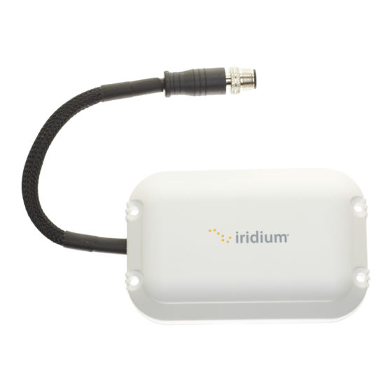
2 Product Overview The Iridium Edge is a finished satellite device with a power supply and antenna in an environmentally sealed enclosure. It contains an Iridium Short Burst Data (SBD) modem which allows remote devices to send and receive satellite messages from anywhere in the world. Iridium SBD service has two message size classes. - Page 24 The Iridium Edge is not a stand-alone satellite device. It must be integrated into an application or solution on the remote side to the Iridium Edge and the backend Application to the Iridium gateway. Remote host devices can control and monitor the Iridium Edge uses through AT commands over a RS232 interface.
-
Page 25: Key Benefits
Built in Iridium satellite antenna 2.2 Scope The Iridium Edge User’s Guide provides specifications for the Iridium Edge hardware along with installation guidelines. It does not provide developer information for software of the Iridium Edge and the Gateway services. 2.3 Reference Documentation Development documentation is available from Iridium for qualified partners. -
Page 26: Physical Specification
2.4 Physical Specification The following two figures show the Iridium Edge views from the top and bottom. Figure 2-3 Iridium Edge Top View Figure 2-4 Iridium Edge Bottom View... -
Page 27: Accessories
2.5 Accessories The Iridium Edge ships with an Accessory Bag with parts for use when the Iridium Edge is installed with a bottom mount screw. More details on this installation is described in Section 5.6 Mounting the Iridium Edge. The Accessory Bag contains the following items as illustrated in the figure below:... -
Page 28: Connector
Dust and Steam Cleaning SAE J1455, Section 4.5.3 At level 4 Low Pressure Storage SAE J1455, Section 4.9.3 At -40C for 48 hours 2.8 Connector The Iridium Edge connector terminates with a pig tail cable that allows for side and bottom cable exits. -
Page 29: Connector Part Numbers
Figure 2-6 Connector 2.8.1 Connector Part Numbers The Iridium Edge uses an eight (8) pin male M12 connector. Connector and recommended mating connector part numbers are provided in the table below. Table 2-3 Connector Specifications Parameter Value M12 – 8 Pin Male... -
Page 30: Enclosure
Optional control line to On/Off Input power down Edge Network Available Output Data port, serial data output Active High when Edge Power Detect Output powered 2.9 Enclosure Dimensioned drawings for the side and top view of the Iridium Edge are shown below:... -
Page 31: Enclosure Dimensions
Mount Holes As per figure below, the Iridium Edge has two screw holes on each of its ends to mount the terminal. It is important to use screws with low profile heads so that satellite antenna performance is not affected. -
Page 32: Plugs
Plugs The Iridium Edge come factory installed with two grey plugs in each of the side channels. If a side exit cable installation is used the plug needs to be removed. As the plugs are for included purely for aesthetic purposes both can optionally be removed. -
Page 33: Enclosure Specifications
Grey Plug material Formosacon FM090 2.10 Pigtail Cable As shown in the figure below, the Iridium Edge has a pigtail cable that terminates with the Iridium Edge’s connector. Figure 2-12 Pigtail Cable The pigtail cable allows the Iridium Edge to be mounted in two configurations from the Iridium Edge ... -
Page 34: Mechanical Specifications
The pigtail cable has a IP67 rating only when properly mated with a recommended mating connector. If a IP67 mating cable is not connected to the Iridium Edge, it must not be stored outdoors or in locations that are subject to water and condensing humidity. -
Page 35: Mass
The following subsections contain interface information for the electrical interfaces of the Iridium Edge. 3.1 Power Interface 3.1.1 Input Specification The table below provides the voltage input specification for the Iridium Edge. The power and ground inputs are reverse polarity protected. Table 3-1 Input Power Specification... -
Page 36: Mating Cable Guidelines
3.1.4 Load Dump Protection The Iridium Edge is designed to operate through voltage transients as per SAE J1455 and survive input large load voltages. The Iridium Edge survives large load dumps by internally disconnecting the input voltage when large voltages are detected. Once the input voltage is restored to a valid operational input,... -
Page 37: Internal Fuse
3.1.6 Startup Times The Iridium Edge uses an internal super capacitor to limit the current which in turn minimizes the voltage drops on the power and ground return. Before the Iridium Edge can reliably start operation, its internal super capacitor must be at least partially charged. The internal super capacitor is charged when a valid voltage is present and when the Iridium Edge is not powered down with the On/Off control line. -
Page 38: Brown Out
Brown Out The Iridium Edge monitors the input voltage. If the input voltage drops too low for reliable operation after a valid input voltage is applied, the internal SBD modem’s is turned off and remains turned off until a valid input voltage is restored. -
Page 39: Baud Rate
The baud rate can be set via the AT+IPR command. However, users are strongly advised to not change the baud rate so the Iridium Edge uses a reliable, fixed baud rate. If the baud rate is changed with the appropriated AT command, be advised that the SBD’s default is restored whenever factory defaults are loaded. -
Page 40: Dtr Settings
3.2.3 DTR Settings The SBD’s DTR setting can be set by AT commands. For Iridium Edge units, the internal SBD’s DTR setting has been updated and saved to flash although the SBD’s internal DTR signal is grounded internally on the Iridium Edge and comes out externally on the Iridium Edge connector. In the event the SBD’s factory default configuration is reloaded, the default DTR setting will be re-enabled. -
Page 41: Recommended Operation
3.3.1 Recommended Operation It is recommended that the On/Off control line, if used, is switched to ground to power down the Iridium Edge. A switch to ground circuit, rather than a switch to power circuit, is recommended as this circuit avoids exposing the On/Off input to power supply transients. -
Page 42: Power Down Consumption
Alternatively, the On/Off control line can be driven directly by a RS232 signal level such as DTR. Figure 3-2 On/Off Using DTR Prior to turning off the Iridium Edge, a “flush memory” (AT*F) command should be issued to ensure all internal SBD modem’s flash memory write activity is completed. -
Page 43: Power Detect Indicator
Iridium Edge’s network status. If the Network Indicator function is not required, this pin should be left disconnected. Network Available is not a guarantee that a message can be successfully sent; instead it reports if it can see an Iridium satellite by measuring the level of the incoming satellite channel. The Network Available state is evaluated every time the satellite channel is received or missed. -
Page 44: Rf Specifications
The Power Detect indicator could potentially be used in applications when the host wants to detect if an Iridium Edge Cable has been tampered. It could also be used during installation to provide feedback if the Iridium Edge has power applied. -
Page 45: Molded Back-Shell
The specifications for Iridium’s Blunt Cut cable are in the appendix. The following general guidelines should be followed to when building mating cables for the Iridium Edge 4.1 Molded Back-shell The mating cable must have a molded back-shell and use IP67 rated cable connectors. -
Page 46: Cable Jacket Properties
A shield cable is recommended to minimize any EMI/EMC that could affect operation of the cable. The cable’s braid should be connected to a single point ground either near the power supply or at the Iridium Edge connector depending on application requirements. -
Page 47: Installation Guidelines
Before an installation, the Iridium Edge’s IMEI number must be recorded along with the installation location. The Iridium Edge’s IMEI number is the network address for the Iridium Edge and it is used for provisioning, billing and to send or receive messages to and from the device. -
Page 48: Restricted Installations
The Iridium Edge includes four additional IMEI labels. These labels are located on the bottom of the Iridium Edge shipping box as per the figure below. If the Iridium Edge is mounted in a difficult to reach place or if its IMEI label is covered, the spare IMEI label can be optionally affixed to an accessible location such that the IMEI can be easily read. -
Page 49: Mounting The Iridium Edge
The Iridium Edge can be mounted in three methods, depending on the installation requirements: screw mount, bottom mount and side/tape mount. The red tape should be left on the Iridium Edge unless the Iridium Edge is double-side mounted with tape. 5.6.1 Screw Mount The Iridium Edge has 4 mounting holes designed to accommodate M4 screws. - Page 50 In the event that the pigtail cable must be removed from the side channels, always keep a thumb over the center of the Iridium Edge where the pigtail connector exits. It is very important to be careful with the pigtail cable when it is not secured in the side channel.
-
Page 51: Bottom Mount
5.6.2 Bottom Mount In the bottom mount configuration, the Iridium Edge is held in place with a single screw. The items in the Accessory Bag are required for this type of installation. ... - Page 52 Figure 5-4 Slotted Screw Installation Carefully press the Rubber Grommet into the baseplate until it is flush with the Iridium Edge. Figure 5-5 Grommet Installation Optionally, fill the two side channels with silicon sealant, taking care that it does not unseat the rubber grommet.
- Page 53 The Spiral Sheath protects the pigtail from chaffing. Unwrap the sheath and wrap it around the pigtail just above the heat shrink. Figure 5-7 Spiral Sheath Firmly press the sheath so that it makes contact with the Iridium Edge’s baseplate and goes inside the Slotted Screw.
-
Page 54: Tape Mount
Iridium Edge’s pigtail connector. 5.6.3 Tape Mount The tape mount is for a permanent installation only. Iridium Edge devices that are installed with tape cannot be removed without damaging or removing the double sided tape. ... -
Page 55: Mating Cable Installation
If the Iridium Edge needs to be removed, do not pry it off the asset. Prying can damage both Iridium Edge or the mounting surface. It is recommended to remove Iridium Edge using a thin wire that is sawed back and forth under Iridium Edge to cut the double sided tape. -
Page 56: Operational Practices
These hazards could cause serious injury or death. Screw the mating cable onto the Iridium Edge so that it is finger tight. Do not use a wrench to tighten the mating cable to the Iridium Edge. 5.8 Operational Practices The following guidelines must be followed when using the Iridium Edge. -
Page 57: Hazardous Locations
5.8.3 Pacemakers The Iridium Edge is designed to and certified for operation such that it is normally more than 20cm (8 inches) from humans. People with pacemakers: • Should ALWAYS keep Iridium Edge more than eight inches from their pacemaker when the device is turned ON. -
Page 58: Disconnecting Mating Connector
5.8.4 Disconnecting Mating Connector The Iridium Edge must not be disconnected from its mating connector and left outdoors or in other environments where water can get inside the Iridium Edge’s pigtail connector and potentially corrode contacts, and void the warranty. -
Page 59: Appendix A: Blunt Cut Cable
6 Appendix A: Blunt Cut Cable A Blunt Cut cable accessory is available from Iridium for its distribution partners. It can be ordered using the part number in the table below Part Number Description EDGE10MBC1601 10m cable with Iridium Edge mating connector It is recommended that partners cut the cable to the required length to ensure a simple clean installation. - Page 60 Figure 7-2 Pin Out Configuration Figure 7-3 Connector...
Need help?
Do you have a question about the EDGE and is the answer not in the manual?
Questions and answers