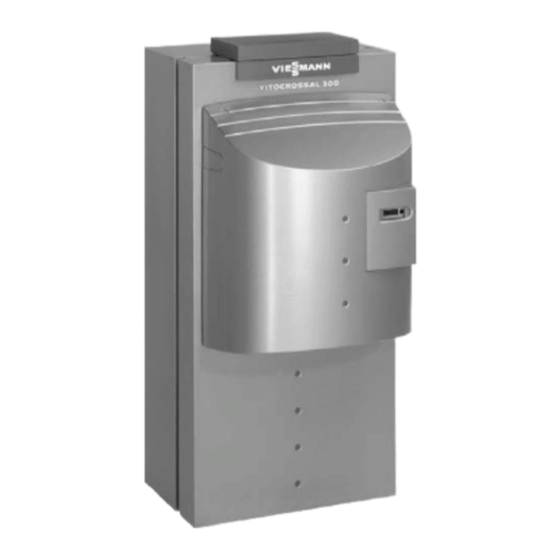
Viessmann Vitocrossal 300 Service Instructions Manual

Viessmann Vitocrossal 300 Service Instructions Manual

Gas fired condensing boiler with matrix−compact gas burner, for open flue and balanced flue operation
Hide thumbs Also See for Vitocrossal 300:
Table of Contents

Advertisement

Quick Links

Service instructions
for heating engineers
Vitocrossal 300
Type CU3
Gas fired condensing boiler with MatriX−compact gas burner,
for open flue and balanced flue operation
See notes on applicability, page 2.
VITOCROSSAL 300
Please keep safe
5692 500 GB
1/2004

Advertisement

Table of Contents
loading

Summary of Contents for Viessmann Vitocrossal 300

  • Page 1 Service instructions for heating engineers Vitocrossal 300 Type CU3 Gas fired condensing boiler with MatriX−compact gas burner, for open flue and balanced flue operation See notes on applicability, page 2. VITOCROSSAL 300 Please keep safe 5692 500 GB 1/2004...
  • Page 2: General Information

    (heating engineer/installation Use only original Viessmann spare contractor). parts, or equivalent parts that have been approved by Viessmann. Before working on the equipment/ heating system, isolate the mains Initial start−up...
  • Page 3: Table Of Contents

    Contents Index Page General information Safety instructions ........................Applicability .
  • Page 4: Initial Start−Up, Inspection And Maintenance

    Initial start−up, inspection and maintenance Steps initial start−up, inspection and maintenance For further instructions on individual steps, see pages indicated. Commissioning steps Inspection steps Maintenance steps Page 1. Checking all safety equipment ..........2.
  • Page 5: Commissioning Steps Inspection Steps Maintenance Steps Page

    Initial start−up, inspection and maintenance Steps initial start−up, inspection and maintenance (cont.) Commissioning steps Inspection steps Maintenance steps Page 22. Checking all connections on primary and DHW side for leaks 23. Checking diaphragm expansion vessel and system pressure 24. Checking function of all safety valves 25.
  • Page 6: Further Details Regarding The Individual Steps

    Initial start−up, inspection and maintenance Further details regarding the individual steps General information regarding initial start−up, inspection and maintenance Please note: The measures described here relate exclusively to gas fired boilers and burners. This comprises only a part of the work prescribed by TRGI ’86/96 relating to the commissioning of a gas fired system.
  • Page 7: Checking All Safety Equipment

    Initial start−up, inspection and maintenance Further details regarding the individual steps (cont.) Checking all safety equipment Check the following settings: Control unit installation and max. 110 ºC High limit safety cut−out service instructions max. 95 ºC Control thermostat ..Check the control unit adjustments and change them, if required.
  • Page 8: Filling The Siphon With Water

    Initial start−up, inspection and maintenance Further details regarding the individual steps (cont.) Filling the siphon with water 1. Release fitting A on siphon B, remove siphon B and fill with water. ¨ Safety instructions There is a risk of flue gas escaping if the siphon is not filled with water.
  • Page 9: C 6. Changing Gas Type (If Required)

    Initial start−up, inspection and maintenance Further details regarding the individual steps (cont.) Changing the gas type (if required) 4. ¨ Safety instructions Insert O−ring D into the groove of new gas restrictor C. 5. Push new gas restrictor C for the prevailing gas type into gas restrictor retainer A (click into place).
  • Page 10: Checking Static And Supply Pressure

    Initial start−up, inspection and maintenance Further details regarding the individual steps (cont.) Checking static and supply pressure ¨ Safety instructions Measure the CO value before and after any work on gas appliances, to prevent any health hazards and to ensure the perfect operational condition of the system.
  • Page 11 Initial start−up, inspection and maintenance Further details regarding the individual steps (cont.) Gas supply pressure (flow pressure) 7. Check the supply pressure (flow 8. Shut down the boiler, close the pressure), see the table below. gas shut−off valve, remove the pressure gauge, and close test nipple "PE"...
  • Page 12: Checking Co Settings

    Initial start−up, inspection and maintenance Further details regarding the individual steps (cont.) Checking CO settings The burner is factory set to natural gas E. During commissioning or maintenance, check the CO level on the boiler adaptor. Please note: The MatriX burner is preset for the entire gas group. Therefore, the burner requires no further setting or adjustment.
  • Page 13: C 9. Checking Gas Valve Control Pressure

    Initial start−up, inspection and maintenance Further details regarding the individual steps (cont.) Checking the gas valve control pressure 4. Connect the gauge to both test nipples A. The differential pressure should be 4.0 mbar (400 Pa). If the actual value deviates by more than "0.4 mbar (40 Pa) H Check the settings of the DIP switches (see page 27)
  • Page 14: Leak Testing Balanced Flue System (Annular Gap Check)

    Initial start−up, inspection and maintenance Further details regarding the individual steps (cont.) Leak testing the balanced flue system (annular gap check) For balanced flue systems tested together with a gas fired boiler, some Federal States (e.g. North Rhine Westphalia) waive the leak test (overpressure test) during commissioning by the flue gas inspector.
  • Page 15: System Shutdown

    Initial start−up, inspection and maintenance Further details regarding the individual steps (cont.) 1. Switch OFF the control unit 7. Switch ON the system ON/OFF ON/OFF switch. switch and check the ionisation current at the upper and lower 2. Pull plug C of the ionisation rated output.
  • Page 16: I M 14. Removing Burner And Checking Burner Gasket

    Initial start−up, inspection and maintenance Further details regarding the individual steps (cont.) Removing the burner and checking the burner gasket 1. Release gas connection pipe B. 2. Release six nuts C, remove the burner and hook into the service position in service holder D on the boiler.
  • Page 17: Checking Burner Gauze Assembly

    Initial start−up, inspection and maintenance Further details regarding the individual steps (cont.) Checking burner gauze assembly Replace the burner gauze assembly if the wire mesh is damaged. 1. Remove ignition and ionisation electrodes A. 2. Turn thermal insulation ring B clockwise and remove carefully.
  • Page 18: I M 16. Checking & Adjusting Ignition & Ionisation Electrodes

    Initial start−up, inspection and maintenance Further details regarding the individual steps (cont.) Checking and adjusting the ignition and ionisation electrodes A Ignition electrodes B Ionisation electrode 1. Check the electrodes for wear and 3. Check all clearances. If the gaps contamination.
  • Page 19: I M 18. Cleaning Combustion Chamber And Heating Surfaces

    Initial start−up, inspection and maintenance Further details regarding the individual steps (cont.) Cleaning the combustion chamber and heating surfaces ¨ Do not use a wire brush or sharp objects. Avoid scratches or other damage to components which are in contact with flue gases.
  • Page 20: Cleaning And Reconnecting The Condensate Drain

    Initial start−up, inspection and maintenance Further details regarding the individual steps (cont.) Cleaning and reconnecting the condensate drain ¨ Safety instructions Clean the inside of the condensate drain at least annually. The flue gas collector, condensate drain, stench trap, neutralising system and all intermediate hoses and pipes are part of the condensate drain system.
  • Page 21: Neutralising System For Leaks

    Initial start−up, inspection and maintenance Further details regarding the individual steps (cont.) Checking the condensate drain and the neutralising system for continuity and leaks installed) Check the condensate drain system Water must be able to flow without for leaks. backpressure via the condensate To do this, fill the open combustion drain system.
  • Page 22 Initial start−up, inspection and maintenance Further details regarding the individual steps (cont.) Burner installation 3. Push plugs fA and lÖ onto the 1. Insert the burner and secure nuts (6 × M 6) by hand. burner control unit. Then tighten diagonally to 3 Nm. 2.
  • Page 23: Troubleshooting

    Troubleshooting Display and programming unit at the burner control unit Display and programming unit Function A display and programming unit is The display is composed of three integrated into the burner control elements comprising seven unit. The display indicates the segments each.
  • Page 24 Troubleshooting Display and programming unit at the burner control unit (cont.) Type of display Status Service (1 digit) (two digits) Operating display in Operating Display "FL" if a Page 25 standard mode condition, see flame signal is table below present Operating display for Message code, Operating...
  • Page 25: H Operating Display

    Troubleshooting Display and programming unit at the burner control unit (cont.) Operating display Please note: In standard mode, the status display shows the current operating state. The service display shows "FL" if a flame is established. Press reset button Status Service Status Service System tests Heat demand...
  • Page 26: Selecting Manual Mode

    Troubleshooting Selecting manual mode Manual mode and service display A heat demand from the control unit must be present to call up the service display and for manual mode. In the service display, the current level of modulation is shown in %. Whereby: "d 00"...
  • Page 27: Setting The Burner Control Unit Parameters

    Troubleshooting Setting the burner control unit parameters DIP switch settings The DIP switches at the back of the display and programming unit of the burner control unit must be set to the rated burner output. For displaying the selected parameter set, see below. For confirming a newly adjusted parameter set (e.
  • Page 28: H Confirming A Parameter Set

    Troubleshooting Setting the burner control unit parameters (cont.) Confirming a parameter set A flashing "p" will be shown under status, if a parameter set has been changed via the DIP switch or the burner control unit has been replaced. The figures below service indicate the selected parameter set (see page 27).
  • Page 29: Diagnostics

    Troubleshooting Diagnostics Fault display The fault display will be activated automatically if the burner control unit switches to a fault state. The last fault will then be displayed. The light segments of the display will flash. Operating display Automatic activation in case of fault state Fault code Status Service...
  • Page 30: H Calling Up The Fault Memory

    Troubleshooting Diagnostics (cont.) Calling up the fault memory The last six faults are saved and may be called up. The order of scans ranges from the most recent to the previous faults. The fault display will be activated from the operating display. The fault memory display will be terminated if no key is pressed within 20 seconds.
  • Page 31: H Faults With Fault Display

    Troubleshooting Diagnostics (cont.) Faults with fault display General process error Fault System Cause Remedy code characteristics display The fan does not Wind influence on Check flue gas stop during the air draught (chimney) pressure switch idle state check Air pressure switch Air pressure switch Replace air pressure contact does not...
  • Page 32 Troubleshooting Diagnostics (cont.) Fault System Cause Remedy code characteristics display No flame after safety Ionisation electrode Adjust ionisation time, ionisation incorrectly adjusted electrode (see flame monitor page 18) signals no flame Cores L1 and N at Check mains supply control unit mains and swap cores supply interchanged Ignition electrodes...
  • Page 33 Troubleshooting Diagnostics (cont.) Fault System Cause Remedy code characteristics display Burner control unit Internal error Replace burner in fault state governor input control unit Internal error pressure switch input Internal fault flame monitor Fault during test of safety inputs Internal fault voltage monitor Internal fault voltage failure...
  • Page 34 Troubleshooting Diagnostics (cont.) Fault System Cause Remedy code characteristics display The fan speed during Fan faulty, cables Check cables, start−up or operation faulty or broken replace fan stays outside its set range longer than 5 s; the speed for ignition setting or start output during operation is not achieved...
  • Page 35: H Faults Without Fault Display

    Troubleshooting Diagnostics (cont.) Faults without fault display Fault Cause Remedy Combustion errors Gas throughput too high Check gas throughput in through pulsation accordance with rated boiler output. boiler output. Check gas inlet Too little or too much air pressure. Condensate backup in Checking condensate flue gas system drain...
  • Page 36: H Burner Control Unit Flow Chart

    Troubleshooting Diagnostics (cont.) Burner control unit flow chart...
  • Page 37 Troubleshooting Diagnostics (cont.) After the controller issues a heat demand, the following program sequence will run: Phase Duration 01 Test for heat demand 02 Idle state check of the air pressure switch 1 to 30 s and the fan 03 Fan ramp up 1 to 30 s (a fault shutdown will be initiated if the air pressure switch does not signal that the air pressure has reached...
  • Page 38: Burner

    Burner Component summary...
  • Page 39 Burner Component summary (cont.) A Boiler door B Ignition electrodes C Fan D Ignition unit E Inlet flange F Flexible gas pipe G Ionisation electrode H Display and programming unit K Burner control unit L Gas combination valve M Air pressure switch N Thermal insulation ring O Burner gauze assembly...
  • Page 40: Burner Control Unit Connection Diagram

    Burner Burner control unit connection diagram Mains 230 V~ 50 Hz Ign. (−) Spd. F6 P Legend A 1 Burner control unit MPA 51 F 1 Main fuse A 2 Display unit with reset function F 6 Air pressure switch H 1 Operating message B 4 M 1 Fan motor with PWM selection H 2 Fault message S 3...
  • Page 41: Parts List

    (from this parts list). 204 Insulating casing Obtain common parts from your 205 Front insulating mat local supplier. 206 Rear insulating mat 208 Vitocrossal 300 inscription Parts 209 Edge protector 001 Flue gas box 210 Decorative cap 002 Flue gas box gasket...
  • Page 42 Parts list Parts list (cont.)
  • Page 43 Parts list Parts list (cont.)
  • Page 44 Parts list Parts list (cont.)
  • Page 45 Parts list Parts list (cont.)
  • Page 46: Appendix

    Appendix Commissioning/service report Setting and test values Set value Initial start−up Date: Static pressure mbar 20 50 mbar Supply pressure (flow pressure) j for natural gas E mbar 17.4 50 mbar j for natural gas LL mbar 17.4 50 mbar Tick gas type Carbon dioxide content CO H at lower rated output...
  • Page 47 Appendix Maint./service Maint./service Maint./service Maint./service...
  • Page 48 Appendix Commissioning/service report (cont.) Setting and test values Set value Maint./service Date: Static pressure mbar 20 50 mbar Supply pressure (flow pressure) j for natural gas E mbar 17.4 50 mbar j for natural gas LL mbar 17.4 50 mbar Tick gas type Carbon dioxide content CO H at lower rated output...
  • Page 49 Appendix Maint./service Maint./service Maint./service Maint./service...
  • Page 50 Appendix Commissioning/service report (cont.) Setting and test values Set value Maint./service Date: Static pressure mbar 20 50 mbar Supply pressure (flow pressure) j for natural gas E mbar 17.4 50 mbar j for natural gas LL mbar 17.4 50 mbar Tick gas type Carbon dioxide content CO H at lower rated output...
  • Page 51 Appendix Maint./service Maint./service Maint./service Maint./service...
  • Page 52: Specification

    Appendix Specification Boiler specification Gas fired boiler, type B, category I 2ELL Rated output range = 50/30 ºC 9 27 12 35 16 49 22 66 = 80/60 ºC 8 24 11 32 15 44 20 60 Rated thermal load range 8 25 11 33 15 46 21 63 Flue gas values Temperature...
  • Page 53 Appendix Specification (cont.) MatriX radiant burner specification Rated output range 9 27 12 35 16 49 22 66 of the boiler Burner type VGM I 1 VGM I 2 VGM I 3 VGM I 4 Voltage Frequency Power consumption Fan speed at rated output 4 256 4 480 5 056...
  • Page 54: Declaration Of Conformity

    This product meets the requirements of the Efficiency Directive (92/42/EEC) for: Condensing boilers The product characteristics determined as system values for Vitocrossal 300 as part of EC type testing according to the Efficiency Directive (see specification table) can be utilised for the energy assessment of heating and ventilation equipment to DIN V 4701 10 specified by the EnEV.
  • Page 55: Manufacturer's Certificate

    Appendix Manufacturer’s certificate acc. to 1 BImSchV We, Viessmann Werke GmbH & Co KG D 35107 Allendorf, confirm that the following product meets the NO limits specified by the 1 BImSchV § 7 (2): Vitocrossal 300 , type CU3 incl. MatriX radiant burner Allendorf, 1 December 2002 Viessmann Werke GmbH &...
  • Page 56: Keyword Index

    Gas restrictors, 9 Gas supply pressure, 11 Gas type, 9 Validity of this manual, 2 Gas type checking, 9 Viessmann Limited Viessmann Werke GmbH & Co Hortonwood 30, Telford D 35107 Allendorf Shropshire, TF1 7YP , GB Tel: +49 6452 70 0...

This manual is also suitable for:

Cu3

Table of Contents