Sign In
Upload
Manuals
Brands
Viessmann Manuals
Boiler
Vitocrossal 300 CA3 2.5
Viessmann Vitocrossal 300 CA3 2.5 Manuals
Manuals and User Guides for Viessmann Vitocrossal 300 CA3 2.5. We have
1
Viessmann Vitocrossal 300 CA3 2.5 manual available for free PDF download: Installation And Service Instructions Manual
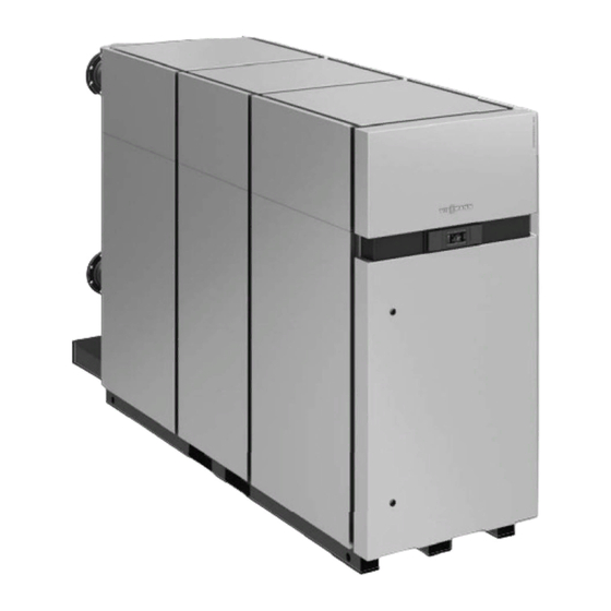
Viessmann Vitocrossal 300 CA3 2.5 Installation And Service Instructions Manual (224 pages)
CA3 Series Gas condensing boiler with cylinder burners
Brand:
Viessmann
| Category:
Boiler
| Size: 7.01 MB
Table of Contents
Safety, Installation and Warranty Requirements
2
Table of Contents
4
Safety
8
General Information
8
Important Regulatory and Installation Requirements
8
Important Regulatory and Installation Requirements
9
About These Installation Instructions
10
Product Information
10
Mechanical Room
11
For Retrofit Applications
11
Recommended Minimum Service Clearance
12
Installation Recommended Minimum Service Clearance
12
Unpacking and Placement of Boiler
13
Reducing Boiler Height
13
Preparing the Boiler
14
Water Side Connection
14
Boiler Connections
15
Electrical Connections
18
Activating the Boiler Section Valves
35
Extension EA1 Accessory (Optional)
36
Making the LON Connection
37
Vitocom 100, LAN 1
38
Vitocom 100, LAN 1 Requirements
39
Operation with Vitotrol App
40
Operation with Vitotrol 100 User Interface
41
Checking Network Settings
41
Vitocom 100, LAN 1 Internal Overview
42
Connecting to the Network (LAN)
42
Vitocom 100, LAN 1 Display and Control Elements
43
Switching on the Vitocom 100, LAN 1
43
Configuring Network Using Static IP
44
Registering the Vitocom 100, LAN 1
45
Function Test
45
Enabling Maintenance
46
Return Vitocom 100, LAN 1 to Factory Set Condition
46
Troubleshooting Measures for Vitocom 100, LAN 1
47
Connecting Flue Gas Pipe
48
Connecting Neutralization System
49
Condensate Connection
50
Gas Connections
51
Initial System Fill
54
System Layout
55
General
55
System Layout 1
56
System Layout 2
57
Boiler Piping in Heating/Cooling Application
58
Venting
59
General Venting Information
59
Venting General Venting Information
60
Connecting Combustion Air Intake for Direct Vent
62
Additional Requirements for Stainless Steel Vent Pipe Material
62
Requirement for UL/ULC Listed Rigid SS/PP(S) Vent Pipe Material
63
Vent Requirements
64
Direct Venting (Two Pipe System)
65
Side Wall Venting
66
Component Installation Guide
66
Elbow - Equivalent Length
66
Vent Termination Location Requirements - Vertical
67
Installation of Support System - PP(S)
67
Venting Options - Stainless Steel/Pp(S)
68
Two Pipe System - Vertical Exhaust/Vertical Air Intake
68
Two Pipe System - Horizontal Exhaust/Horizontal Air Intake
70
Two Pipe System - Vertical/Horizontal Installations
71
Individual Burner Intake Ducting
72
Single Pipe System - Vertical Exhaust/Room Air Dependant
73
Single Pipe System - Horizontal Exhaust/Room Air Dependant
74
Multiple Boiler Installations
75
General Service Information
76
Service Equipment
76
Important Regulatory and Installation Requirements
77
Safety Instructions
78
Service
80
Filling the Heating System with Water and Ventilating
80
Filling Condensate Trap with Water
80
Checking the Type of Gas
80
Service Filling the Heating System with Water and Ventilating
80
Operating the System
81
Adjusting the Heating Curve
84
Integrating the Control Unit into the LON
86
Preparing for Service Work on the Boiler and Burner
88
Reducing Operational Output (if Required)
90
Checking Static and Connection Pressure
91
Checking the Rotary Damper Setting
92
Checking the Burner Damper Setting
92
Measuring CO Content
93
Displaying Ionization Current
95
Turning the System off
95
Dismantling the Burner
96
Burner Parts
98
Display and Programming Unit of Burner Control Unit
99
Coding Card on Burner Control Unit
99
Burner Control Unit
100
Fuel Conversion NG to LPG
100
Converting Gas Type
102
Burner Interface Panel
103
3A and 3B Boiler Temperature Sensor Description
104
Boiler Water Temperature Sensor
105
Boiler Secondary Temperature Sensor
106
Manual Reset Limits
107
Gas Valve
108
Air Pressure Switches
108
Ignition Unit
111
Ignition Cables
112
Rotary Damper and Servomotor
112
Replacing the Solenoid Valve
112
Fan
113
Checking and Cleaning the Burner Tube
113
Checking the Ignition Electrodes and Ionization Electrode
114
Cleaning the Burners
114
Cleaning the Combustion Chamber and Heating Surfaces
115
Checking Heating Water Connections for Leakage
116
Cleaning the Condensate Drainage System
116
Further Assembly and Commissioning
117
Checking for Flue Gas Leakage
117
Gas Valve
117
Checking On-Site Gas Connections for Leakage
118
Taking Final Measurement Reading
118
Checking the Water Conditions
118
Checking Expansion Tank and System Pressure
121
Mixing Valve Movement and Leak Check
121
Checking Air Intake in the Installation Room (Visual Check)
122
Replacing the Supply Air
122
Operation
122
Instructing the Operator of the System
122
Operating and Service Documents
122
Boiler Water Temperature Control
123
Cascade Control Unit
123
Heating Circuit Control
128
DHW Tank Temperature Control
132
Calling up Coding Levels
135
Resetting Coding to Their Factory Set Condition
135
General" Group
136
Combustion Controller" Group
138
Boiler" Group
138
Cascade" Group
139
DHW" Group
141
Solar" Group
142
Heating Circuit
143
General" Group
147
Combustion Controller" Group
155
Boiler" Group
156
Cascade" Group
156
DHW" Group
159
Solar" Group
161
Heating Circuit
165
Calling up the Service Menu
171
Leaving the Service Menu
172
Change Passwords
172
Resetting All Passwords to Factory Settings
172
Scanning Operating Data
172
Resetting Operating Data
172
Brief Scan
173
Carrying out an Actuator Test
174
Checking Sensors
175
Maintenance Display
175
Fault Display
176
Boiler System Fault Codes
177
Burner Fault Codes
183
Sensors
186
Burner Control Unit
187
Resetting Operating Parameters to Factory Settings
191
Manual Mode and Service Display
191
Burner Control Unit Flow Diagram
192
Faults
194
Fault Codes
195
Faults Without Fault Display
198
Burner Control Unit Connection Diagram
199
Boiler Connections
201
Overview
203
PCB Extension for Heating Circuits 2 and 3 with Mixing Valve
204
PCB Low Voltage
204
Pcb 120V
205
Parts Lists
206
Technical Data
218
Boiler Dimensions
220
Requirements for Water Conditions
221
Maintenance Records
222
Maintenance Schedule
222
Advertisement
Advertisement
Related Products
Viessmann Vitocrossal 300 CA3 3.0
Viessmann Vitocrossal 300 CA3 4.0
Viessmann Vitocrossal 300 CA3 5.0
Viessmann Vitocrossal 300 CA3 6.0
Viessmann Vitocrossal 300 CA3 3.5
Viessmann Vitocrossal 300 CA3B
Viessmann VITOCROSSAL 300 Type CR3B
Viessmann Vitocrossal 300 CU3 Series
Viessmann Vitocrossal 300 CT3-57
Viessmann Vitocrossal 300 CT3-89
Viessmann Categories
Boiler
Toy
Control Unit
Heat Pump
Solar panel
More Viessmann Manuals
Login
Sign In
OR
Sign in with Facebook
Sign in with Google
Upload manual
Upload from disk
Upload from URL