Table of Contents
Advertisement
IMPORTANT SAFETY INFORMATION: Always read this manual first before attempting to service this
fireplace. For your safety, always comply with all warnings and safety instructions contained in this
manual to prevent personal injury or property damage.
Dimplex North America Limited
1367 Industrial Road Cambridge ON Canada N1R 7G8
1-888-346-7539 www.dimplex.com
In keeping with our policy of continuous product development, we reserve the right to make changes without notice.
© 2015 Dimplex North America Limited
Service Manual
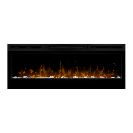
Model
BLF5051
UL Part Number
6909520100
REV
PCN
DATE
00
-
17-JUL-15
7400870000R00
Advertisement
Table of Contents

Subscribe to Our Youtube Channel
Related Manuals for Dimplex Prism BLF5051


Summary of Contents for Dimplex Prism BLF5051
- Page 1 Dimplex North America Limited 17-JUL-15 1367 Industrial Road Cambridge ON Canada N1R 7G8 1-888-346-7539 www.dimplex.com In keeping with our policy of continuous product development, we reserve the right to make changes without notice. © 2015 Dimplex North America Limited 7400870000R00...
-
Page 2: Table Of Contents
NOTE: Procedures and techniques that are considered important enough to emphasize. CAUTION: Procedures and techniques which, if not carefully followed, will result in damage to the equipment. WARNING: Procedures and techniques which, if not carefully followed, will expose the user to the risk of fire, serious injury, or death. www.dimplex.com... -
Page 3: Operation
OPERATION Figure 2 Figure 1 Floating Display WARNING: This electric firebox must be properly in- D & E. Thermostat Controls stalled before it is used. Adjusts the temperature set point to your individual require- The unit can be controlled by either the manual controls ments. -
Page 4: Maintenance
Battery must be recycled or disposed of properly. Check with your Local Authority or Retailer for recyc- ling advice in your area. Battery must be recycled or disposed of properly. Check with your Local Authority or Retailer for recycling advice in your area. www.dimplex.com... -
Page 5: Exploded Parts Diagram
EXPLODED PARTS DIAGRAM Replacement Parts List 13. Floating Display™ Assembly ..3001470100RP 1. Element ......2200510500RP 2. -
Page 6: Wiring Diagram
RGB LED STRIP FLICKER MOTOR MOD A 5-KEY SWITCH BOARD DISPLAY ASSY ELEMENT RELAY BOARD CUT OUT MOTOR HEATER FLAME COLOR TOP LIGHT BLOWER LOG MEDIA LED DRIVER BOARD MAIN BOARD JUNCTION BOARD LED DISPLAY BOARD RGB LED STRIP FLICKER MOTOR www.dimplex.com... -
Page 7: Preparation For Service
PREPARATION FOR SERVICE Figure 3 Mounts (4) NOTE: All components are replaceable from the front of the fireplace while the unit is mounted on the wall, with Hooks (4) the exception of replacement of the power cord. NOTE: If the power cord needs replacing or if the unit needs to be removed from the wall for any other reason please begin service by following the “PREPARATION FOR SERVICE”... -
Page 8: Surface Mount
Recessed Mount - Partial In-wall (Figure 7) Mounting Holes Tools Required: Philips head screwdriver CAUTION: Follow “Preparation for Service” instructions before proceeding. 1. Remove the 4 mounting screws located approximately 3 inches deep in the space between the outer and www.dimplex.com... -
Page 9: Flush Mount - Complete In-Wall
inner casing on the left and right hand side. There are Flush Mount – Complete In-wall (Figure 9) 2 screws per side, upper and lower going into a stud. (Figure 8) Tools Required: Philips head screwdriver CAUTION: The fireplace should be supported while CAUTION: Follow “Preparation for Service”... -
Page 10: Led Media Strips Replacement
Pull the front panel forward from the topside by approximately 2” inches. There are 3 additional screws located underneath the front face but do not need to be removed. There should be enough “give” to allow the panel to pull slightly forward. www.dimplex.com... -
Page 11: Floating Display Assembly Replacement
board. CAUTION: Follow “Preparation for Service” instructions 5. Ensure that all cords are replaced in the same manner before proceeding. as prior to the service. 1. In the upper right hand corner of the unit, above the floating display board, locate the control board cover 6. -
Page 12: Thermistor Replacement
1 in (25.4 mm) from the unit, on either end. the hole that the wires pass to the top of the unit, strip 3. Install the new board onto the unit. off 1/2 in (12.7 mm) the end of each wire and insert www.dimplex.com... -
Page 13: Element Replacement
the end of the wire from the flicker motor and the wire tween the end of the connectors and the element to release from the unit (ensure the colours correspond), into the the wires. provided connectors and with pliers squeeze to make NOTE: Some of the wires may have a “piggy-back”... -
Page 14: Blower/Fan Replacement
NOTE: Using a flat head screwdriver gently pry be- tween the end of the connectors and the blower/fan to release the wires. 7. Properly orient the new blower/fan assembly and con- nect all of the wiring connections. 8. Reassemble in the reverse order as above. www.dimplex.com... -
Page 15: Troubleshooting Guide
TROUBLESHOOTING GUIDE PROBLEM CAUSE SOLUTION PART NUMBER General Circuit breaker trips or fuse Short in unit wiring. Trace wiring in unit. blows when unit is turned on Improper circuit current rating Additional appliances may exceed the current rating of the circuit breaker or fuse. Plug unit into another outlet or install unit on a dedicated 15 amp circuit. - Page 16 Flicker rod hitting or rubbing Grinding or excessive noise Ensure rod is straight and mounted properly with the heater off against internal components in the bracket, spinning freely away from other components. Replace if necessary. Defective Flicker Motor Replace Flicker Motor 2000500100RP www.dimplex.com...
Need help?
Do you have a question about the Prism BLF5051 and is the answer not in the manual?
Questions and answers