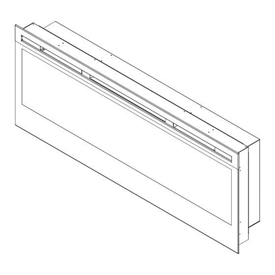
Dimplex BLF50 Service Manual
Hide thumbs
Also See for BLF50:
- Owner's manual (24 pages) ,
- Service manual (19 pages) ,
- Owner's manual (25 pages)
Table of Contents
Advertisement
Quick Links
IMPORTANT SAFETY INFORMATION: Always read this manual first before attempting to service this
fireplace. For your safety, always comply with all warnings and safety instructions contained in this
manual to prevent personal injury or property damage.
Dimplex North America Limited
1367 Industrial Road Cambridge ON Canada N1R 7G8
1-888-346-7539 www.dimplex.com
In keeping with our policy of continuous product development, we reserve the right to make changes without notice.
© 2011 Dimplex North America Limited
Service Manual
Model
BLF50
UL Part Number
6906780100
REV
PCN
DATE
00
-
21-JUL-11
7400360000R00
Advertisement
Table of Contents

Summary of Contents for Dimplex BLF50
- Page 1 Dimplex North America Limited 1367 Industrial Road Cambridge ON Canada N1R 7G8 DATE 1-888-346-7539 www.dimplex.com 21-JUL-11 In keeping with our policy of continuous product development, we reserve the right to make changes without notice. © 2011 Dimplex North America Limited 7400360000R00...
-
Page 2: Table Of Contents
NOTE: Procedures and techniques that are considered important enough to emphasize. CAUTION: Procedures and techniques which, if not carefully followed, will result in damage to the equipment. WARNINg: Procedures and techniques which, if not carefully followed, will expose the user to the risk of fire, serious injury, or death. www.dimplex.com... -
Page 3: Operation
OPERATION Remote Control The fireplace is supplied with a radio frequency remote The BLF50 operates in a 3-Stage process. These control. This remote control has a range of approximately stages can be controlled either by the remote control 50 feet (15.25 m), it does not have to be pointed at the... -
Page 4: Exploded Parts Diagram
ExPLODED PARTS DIAgRAM Replacement Parts List BLF50 Part Number 6906780100 Element ......2200510500RP Remote Receiver . -
Page 5: Wiring Diagram
WIRINg DIAgRAM... -
Page 6: Preparation For Service
Set it aside in a safe place. www.dimplex.com... -
Page 7: Instructions For Removing From Wall
Figure 6 " (123 cm) 46" (116 cm) 3" (7.6 cm) 7" (17.8 cm) " (128 cm) 16" 18" (40.6 cm) (45.7 cm) (49.5 cm) " (9.7 cm) • Put the mirror with the rubber protective strip at the fore proceeding. top and secure with the side mounting brackets Partially unscrew the rear mounting screws that are holding •... -
Page 8: Recessed Mount - Partial In-Wall
Once repair is complete, reassemble in the reverse order as repair being performed. above. Once repair is complete, reassemble in the reverse order as above. Figure 8 Figure 10 Mounting Holes Wall Surface Mounting Hole Figure 9 Mounting Holes www.dimplex.com... -
Page 9: Led Light Strips Replacement
LED LIgHT STRIPS REPLACEMENT using the 2 orange wire connectors from STEP 6. (One connects the red wire to the black/orange wire; and the Tools required: Phillips head screw driver other connects the yellow wire to the solid black wire). Small cutter or snips Tuck wires back into control panel area. -
Page 10: Element Replacement
Locate the temperature limit switch and remove the are also connected to this piece, so carefully move it mounting screw. farther down in the body of the unit, to give some room to access the heater assembly housing. Disconnect the wiring connections noting their original www.dimplex.com... -
Page 11: Blower/Fan Assembly Replacement
locations Pliers may be required for grip when discon- switches on the top right. Remove cover and set aside. necting the wire/spade connectors. Remove the panel that spans across the top front facia. Cut and remove plastic cable tie that hold the wires in To do so, locate 4 screws, (2) on the left and (2) right place on the top of the panel. -
Page 12: Remote Receiver Board Replacement
If they are not acces- sible, you can still proceed with them attached and pulling the front panel forward from the top end by ap- proximately 2” inches. Remove the electrical junction box cover located on the www.dimplex.com... -
Page 13: Assembly Part Pictures
ASSEMBLY PART PICTURES 3-STAgE REMOTE RECEIVER BOARD LED DRIVER BOARD SWITCH HOUSINg - Outside View SWITCH HOUSINg - Inside View... - Page 14 LOWER ELECTRICAL HOUSINg With Housing-Cover and Flicker Rod in place LOWER ELECTRICAL HOUSINg With Housing-Cover and Flicker Rod Removed LED LIgHT STRIPS www.dimplex.com...
- Page 15 LED LIgHT STRIP WIRE HARNESS HEATER ASSEMBLY ELEMENT CONNECTIONS Left and Right Side...
- Page 16 HIgH TEMPERATURE CUTOUT Below Element Housing BLOWER MOTOR CONNECTIONS Below Element Housing www.dimplex.com...


Need help?
Do you have a question about the BLF50 and is the answer not in the manual?
Questions and answers