McIntosh MA6900 Service Manual
Hide thumbs
Also See for MA6900:
- Owner's manual (24 pages) ,
- Brochure & specs (4 pages) ,
- Programming manual (21 pages)
Advertisement
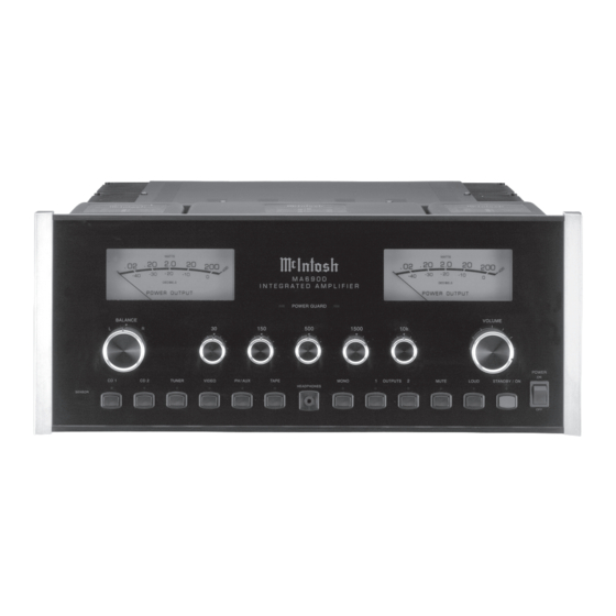
INTEGRATED AMPLIFIER
Performance Specifications ........................................ 2
Notes ......................................................................... 2
Rear Panel .................................................................. 3
Section Location ........................................................ 4
Block Diagram ...................................................... 5 - 6
Interconnection Diagram ...................................... 7 - 8
Main Schematic and PCB .................................... 9 - 18
Balanced Schematic and PCB .............................. 12, 18
Heatsink Schematic and PCB ............................. 19 - 20
CONTENTS
SERVICE MANUAL
Capacitor Schematic and PCB ........................... 21 - 22
Control Schematic and PCB .............................. 23 - 26
Lamp Schematic and PCB ................................. 25 - 26
Tone Schematic and PCB .................................. 27 - 31
Keyboard Schematic and PCB ........................... 30 - 32
Parts List ............................................................ 33 - 36
Repacking Instruction .............................................. 41
Advertisement
Table of Contents

Related Manuals for McIntosh MA6900


Summary of Contents for McIntosh MA6900
-
Page 1: Table Of Contents
INTEGRATED AMPLIFIER CONTENTS Performance Specifications ........2 Capacitor Schematic and PCB ......21 - 22 Notes ................. 2 Control Schematic and PCB ......23 - 26 Rear Panel ..............3 Lamp Schematic and PCB ......... 25 - 26 Section Location ............4 Tone Schematic and PCB ........ -
Page 2: Performance Specifications
PERFORMANCE SPECIFICATIONS Input Impedance Power Output Phono, 47k ohms, 65pF Minimum sine wave continuous average power output per High Level, 22k ohms channel, all channels operating is: 200 watts into 2 ohm load Maximum Input Signal 200 watts into 4 ohm load Phono, 90mV 200 watts into 8 ohm load High Level, 8V... -
Page 3: Rear Panel
MA6900 REAR PANEL... -
Page 4: Section Location
SECTION LOCATIONS TOP VIEW WITH COVER REMOVED BOTTOM VIEW WITH COVER REMOVED... -
Page 5: Block Diagram
MA6900 BLOCK DIAGRAM... - Page 6 INTERCONNECT...
- Page 7 MA6900 MAIN 049688 1 OF 3...
- Page 8 MAIN 049688 2 OF 3 BALANCED...
- Page 9 MA6900 MAIN 049654 3 OF 3...
- Page 10 MAIN 049654 BALANCED 049654B...
- Page 11 MA6900 HEATSINK 4A 4B 049665...
- Page 12 CAPACITOR 049653...
- Page 13 MA6900 CONTROL 049655...
- Page 14 CONTROL PCB 049655 LAMP 7A 7B 049235...
- Page 15 MA6900 TONE 049656...
- Page 16 TONE 049656 KEYBOARD 049696...
-
Page 17: Parts List
MA6900 PARTS LIST K1 K2 K3 K4 K5 K6 K7 K8 K9 K10 K11 RLY REED FORM 1A 5V 500OHMS 08705000 K12 K13 K14 K15 K16 K17 K18 RLY REED FORM 1A 5V 500OHMS 08705000 RELAY POWER TV5 24V 08706900 Reference No. - Page 18 PARTS LIST con’t R14 R15 RES MF 1K 1% 1/4W 14409000 RES MF 2.21 OHM 1/4W 1% 14437800 RESONATOR CERAMIC 6.0MHZ W/CAP 18003900 Reference No. Description Part No. 049235 LAMP PCB DS1 DS2 DS3 LAMP 14V #7373 05812000 4 PIN RT. ANGLE 11724000 049665 HEATSINK PCB CONN.
-
Page 19: Exploded View
MA6900 EXPLODED VIEW... - Page 20 EXPLODED VIEW EXPLODED PARTS LIST Item Part Description 016456 GLASS 018691 HEATSINK 148073 INPUT POWER SWITCH 084194 ISOSTRATE 017531 PUSHBUTTON ASSY RED 112087 SPACER PCB 1/4 017517 PUSHBUTTON ASSY BLK 749665 HEATSINK PCB ASSY 078033 O-RING 414118 CLIP TRANSISTOR 218 749695 KNOB ASSY 414119...
-
Page 21: Repacking Instruction
MA6900 REPACKING INSTRUCTIONS... - Page 22 SERVICE MANUAL The continuous improvement of it’s products is the policy of McIntosh Laboratory Incorporated, who reserve the right to improve design without notice. Because of the constant upgrading of McIntosh products’ circuitry and components, the Company cannot insure, and does not warrant, the accuracy of the within schematic material, which is intended for information only.
Need help?
Do you have a question about the MA6900 and is the answer not in the manual?
Questions and answers