Table of Contents
Advertisement
Advertisement
Table of Contents

Subscribe to Our Youtube Channel
Related Manuals for McIntosh MA252


Summary of Contents for McIntosh MA252
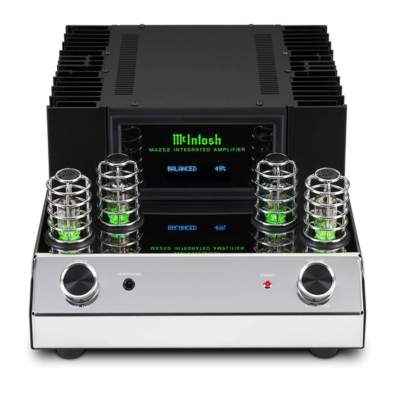
- Page 1 MA252 Integrated Amplifier Owner’s Manual...
-
Page 2: Table Of Contents
Customer Service Setup Mode: Your decision to own this McIntosh MA252 Integrated If it is determined that your McIntosh product is in How to Operate the Setup Mode ........19 Amplifier ranks you at the very top among discrimi- need of repair, you can return it to your Dealer. You Setup Functions: nating music listeners. -
Page 3: Important Information
IMPORTANT! INSTRUCTIONS FOR REMOVAL OF FOAM INSERT OVER THE VACUUM TUBES PRIOR TO CONNECTING THE A.C. POWER SUPPLY CORD, START ON THE NEXT PAGE. - Page 4 McIntosh Service Agency. Follow the steps below to pre- pare the MA252 for operation: 1. Orient the MA252 so the Front and Top of the Figure D Integrated Amplifier is facing you. Refer to Figure B figure A.
-
Page 5: Unpacking The Ma252
Unpacking the MA252 5. The MA252 Integrated Amplifier has four Small Vacuum Tubes that are inserted into special Vacuum Tube Sockets on the Stainless Steel Chas- WARNING: sis. Refer to figure E. Each of the Tube Sockets have four pin openings to accept the Vacuum Tube Shield Covers. -
Page 6: General Information
MA252. go to www.mcintoshlabs.com. for Loudspeaker Connection, the spade 2. Apply AC Power to the MA252 and other McIntosh 8. When discarding the unit, comply with local rules lugs need an opening of at least 3/10 inch Component(s) only after all the system components or regulations. -
Page 7: Introduction
10dB of boost or cut. The MA252 remembers the Bass • Power Output and Treble Setting for each input. The MA252 consists of 100 watts (8 ohm) or 160 watts (4 ohm) per channel Stereo Power Amplifier with • Multifunction Display less than 0.03% distortion. -
Page 8: Dimensions
Dimensions Dimensions The following dimensions can assist in determining the best location for your MA252. There is additional information on the next page pertaining to installing the MA252 into cabinets. Left Side View of the MA252 Front View of the MA252 "... -
Page 9: Installation
Installation Installation The MA252 Integrated Amplifier is designed to be placed upright on a table or shelf, standing on its feet. The required ventilation requirements are shown. Always provide adequate ventilation for your MA252. 6" Cool operation ensures the longest possible operating 15.3cm... -
Page 10: Rear Panel Connections
UNBALanced INPUTS live AC outlet. Refer to information full frequency range Audio 1 and 2 accept high level on the back panel of your MA252 to Output for connection to program source signals determine the correct voltage for your an actively powered Sub-... -
Page 11: Connecting Components
3. Connect any additional McIntosh Components in a similar manner, as outlined in steps 1 thru 2. Data Control Connections: 4. Connect a Control Cable from the MA252 DATA PORT Jack to the CD Player Data In Jack. 5. Connect another McIntosh Component in a similar manner instead of the CD Player Data In Jack, as outlined in step 7. - Page 12 Connecting Components Connect to AC Outlet Turntable CD Player...
- Page 13 The connection instructions below, together with the tion” Note 6 on page 6 for additional information. Notes: 1. If desired, the twisted ends can be tinned MA252 Connection Diagram located on the next page WARNING: Loudspeaker terminals are hazard- with solder to keep the strands together.
-
Page 14: Connecting Loudspeakers
Connecting Loudspeakers 5. Connect the MA252 power cord to an active AC outlet. Spade Lug or Wire Connections: 6. Connect the Loudspeaker hookup cables to the MA252 Negative Output Terminal and Positive Output Terminal to the Loudspeaker Terminal Connections being careful to observe the cor- rect polarities. -
Page 16: Remote Control Push-Buttons
Stop CD Playback Selects the desired INPUT Selects Next Track during CD Playback Pause CD Playback Selects Previous Track during CD Playback Starts CD Playback Note: Push-buttons whose function is not identified above are for use with other McIntosh Products. -
Page 17: How To Use The Remote Control
How to use the Remote Control How to use the Remote Control The supplied Remote Control performs the various Operating Functions for the MA252 Integrated Am- plifier. Note: Refer to the “How to Operate” Section of this manual for additional information. -
Page 18: Front Panel Displays, Controls And Jack
IR Sensor receives The control is also used to enter the nels. Switches the MA252 ON or OFF commands from a TRIM or SETUP Modes and select (Standby). Also used to change the... -
Page 19: Setup Mode
PUT)”. Refer to figure 3. software that is know as Firmware. The Firmware for make changes to the factory default settings, a Setup the MA252 and can be identified at any time by utiliz- SETUP: Inputs Feature is provided to customize the operating settings ing the Setup Mode. - Page 20 (refer to page 8, step 6). the character “B” to “C”. Refer to figure 10. SETUP: UNBAL 2 The MA252 Default Input Names (UNBAL 1, BAL, RENAME: BAL On/Name(Hold IN) PHONO, etc.) as indicated on the Front Panel Dis- >CAL...
-
Page 21: Data Port
ALTERNATE Codes. The Al- Data Port figure 14. ternate Codes are used when the MA252 is used in the Data Port Connection between the MA252 and a same location as another McIntosh Preamplifier and/or... -
Page 22: Ir Sensor
IR Sensor Power Mode Factory Reset The MA252 Front Panel Sensor, which receives the The MA252 incorporates an Auto Off Feature, which If it becomes desirable to reset all the adjustable set- signals from the HR091 Remote Control, can be... -
Page 24: How To Operate The Ma252
Trim Function. illumination color of the Small Signal Vacuum Then use the VOLUME Ad- lights to indicate the MA252 is in Standby mode. To Tubes will change to the Green Color. just Control to change the switch ON the MA252, Press the VOLUME Control setting. -
Page 25: Trim Level
Tone Controls perform the following: Source Components can have slightly different volume BASS 1. Select the desired Input Source. levels resulting in the need to readjust the MA252 +10dB 2. Press the TRIM Push-button on the Remote Con- Volume Control when switching between different Figure 64 trol until “TONE CONTROLS, On”... -
Page 26: Treble Control
“TREBLE, 0 dB” appears on the Front Panel Press the Front Panel INPUT/TRIM Control to ac- Information Display. Refer to figure 66. tivate the MA252 Trim Functions. Rotate the Front INFORMATION DISPLAY 2. Rotate the VOLUME Control or press the ◄ ►... -
Page 27: Protection Circuitry And Microprocessor Reset
LED Illumination will change to the amber color. Protection Circuitry In the event the MA252 over heats, due to improper ventilation, high ambient temperature and/or imped- ance mismatch, the internal protection circuits will activate. The small Signal Vacumn Tubes normal LED Illuminated Color of Green, will change to an Amber Color. -
Page 29: Photos
Photos... -
Page 30: Specifications
240 Volts, 50/60Hz at 1.9 amps 20Hz to 20,000Hz Standby: Less than 0.5 watt SUB (Mono) Output Impedance Note: Refer to the rear panel of the MA252 for the cor- 200 ohms Total Harmonic Distortion rect voltage. 0.03% maximum with both channels operating from 250... -
Page 31: Packing Instructions
Failure to do this will result in shipping Accesories damage. To protect the tubes during shippment, the Foam Insert removed from the MA252 needs to be re-insert- ed. Follow the unpacking instructions on pages 4-5 in the reverse order. Use the original shipping carton and interior parts only if they are all in good serviceable condition.
Need help?
Do you have a question about the MA252 and is the answer not in the manual?
Questions and answers