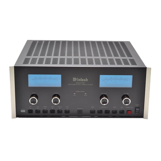
McIntosh MA6500 Service Manual
Hide thumbs
Also See for MA6500:
- Owner's manual (20 pages) ,
- Brochure & specs (4 pages) ,
- Brochure (2 pages)
Advertisement
INTEGRATED AMPLIFIER
WA T TS
.
2.0
20
.
02
-
-
2 0
3 0
-
4 0
D E C IB EL S
P O W E R O U T P U T
B A S S
C D 1
C D 2
T U N E R
S E N S O R
Performance Specifications ........................................ 2
Notes ......................................................................... 3
Rear Panel .................................................................. 4
Section Location ........................................................ 4
Block Diagram ...................................................... 5 - 8
Interconnection Diagram .................................... 9 - 10
Input Driver Schematic and PCB ....................... 11 - 18
Heatsink Schematic and PCB ............................ 19 - 20
20
20 0
-
10
0
P O W E R G U A R D
T R E B L E
L E F T
V ID E O
P H A U X
/
T A P E
CONTENTS
SERVICE MANUAL
.
02
B A L A N C E
R IG H T
L
M O N O
1
S P E A K E R S
H E A D P H O N E S
Lamp Schematic and PCB ................................. 19 - 20
PG Display Schematic and PCB ........................ 21 - 22
Control Schematic and PCB .............................. 21 - 22
Tone Schematic and PCB .................................. 23 - 26
Parts List ............................................................ 25 - 28
Exploded View and Parts List ............................. 29 - 31
Repacking Instructions ............................................. 33
WA T TS
.
2.0
20
20
20 0
-
-
2 0
-
3 0
10
-
4 0
0
D E C I B EL S
P O W E R O U T P U T
V O L U M E
R
2
M U T E
L O U D
S T A N D B Y
/
O N
Advertisement
Table of Contents

Related Manuals for McIntosh MA6500


Summary of Contents for McIntosh MA6500
-
Page 1: Table Of Contents
INTEGRATED AMPLIFIER WA T TS WA T TS 20 0 20 0 D E C IB EL S D E C I B EL S P O W E R O U T P U T P O W E R O U T P U T P O W E R G U A R D B A S S T R E B L E... - Page 2 PREFORMANCE SPECIFICATIONS POWER OUTPUT, STEREO INPUT IMPEDANCE 250, 200, 120 watts minimum sine wave continuous Phono: 47k ohms, 65pF average power output per channel, both channels operat- High Level: 22k ohms ing, into a load impedance of 2, 4 and 8 ohms respec- tively.
-
Page 3: Notes
MA6500 NOTES 1. The heavy lines on the schematics denote the primary Front panel controls are set at: signal path. BALANCE ........CENTER DETENT TREBLE BASS ......CENTER DETENT 2. Unless otherwise noted, all voltages indicated on the INPUT SELECTORS ........TUNER schematics are measured under the following condi- LOUDNESS ............ -
Page 4: Rear Panel
REAR PANEL W A R N IN G M A 6 5 0 0 I N T E G R A T E D A M P L I F I E R S H O C K H A Z A R D - D O N O T O P E N . FO R C O N T IN U E D P R O TE C TI O N A G A IN S T FI R E H A Z A R D M c IN TO S H LA B O R AT O R Y, IN C ., B IN G H A M T O N , N E W Y O R K M A D E IN U S A R E P L A C E O N LY W IT H S A M E T Y P E A N D R AT IN G F U S E . -
Page 5: Block Diagram
MA6500 BLOCK DIAGRAM HEAD- PHONE TUNER INPUT LEFT ELECTRO- TO PREAMP IN (INT) VIDEO CHANNEL MONO SUPER TRACKING 20dB BALANCE TONE OUTPUT MAGNETIC INPUTS TAPE SWITCHING VOLUME CONTROL CONTROL MUTING SWITCHING PREAMP OUT LEFT LOUDNESS TURN-ON R IAA COMPENSATION DELAY PHONO CONTROL OUTPUT... - Page 6 BLOCK DIAGRAM POSITIVE CURRENT LIMITER LEFT OUTPUT CASCODE SPEAKER 1 LEFT PG POWER DIFF SPEAKER INDICATOR VOLTAGE INDICATOR GUARD PREDRIVER DRIVER OUTPUT SWITCHING DRIVER SPEAKER 2 CURRENT SOURCE BIAS TO PRE AMP OUT (INT) POWER AMP PRE AMP LEFT ELECTRONIC INPUT (INT) ATTENUATOR...
- Page 7 MA6500 INTERCONNECT...
- Page 8 INPUT DRIVER 049193 SH 1 OF 3...
- Page 9 MA6500 INPUT DRIVER 049193 SH 2 OF 3...
- Page 10 INPUT DRIVER 049193 SH 3 OF 3...
- Page 11 MA6500 INPUT DRIVER...
- Page 12 HEATSINK 3A 3B 049194 LAMP 049235...
- Page 13 MA6500 PG DISPLAY 049236 CONTROL 049195...
- Page 14 TONE 049268...
-
Page 15: Parts List
MA6500 TONE 049268 PARTS LIST PART NO DESCRIPTION REFERENCE NO 132223 TRANSISTOR NPN MPS4124 2K/REEL Q44 Q46 Q47Q57 Q58 066462 ELECT CAP 1O UF 100VDC AMMO C35 C36 C37 C38 Q59 Q61Q63 Q66 Q75 066469 ELECT CAPACITOR 470MF 50V T&R C176 049193 INPUT DRIVER Q78 Q79 Q80 Q81 Q83... - Page 16 PARTS LIST con’t 049195 CONTROL 133260 DUAL OPERATIONAL AMPLIFIER IC1 IC2 IC3 IC4 144097 METAL FILM RES 4.75K 1% 1/4W R46 R86 R177 R222 058153 INCANDESCENT LAMP 14V 100MA DS13 DS14 DS15 DS16 134457 POT, EQUAL R33 R34 R227 R233 R234 DS17 DS18 134464 POTENTIOMETER BALANCE 2KOHM...
- Page 17 MA6500 EXPLODED VIEW...
-
Page 18: Exploded View And Parts List
EXPLODED VIEW PARTS LIST NOTES Ref. Part Description 016404 FRONT PANEL GLASS 101059 SM 6 X 5/8 PHIL PAN TYPE A 004899 EXTRUSION BRACKET 114119 TRANSISTOR CLIP 214 018612 END CAP 114118 TRANSISTOR CLIP 218 101042 TS 4-40 X 1/2 SLOT FILLISTER 112087 PCB SPACER 1/4”... -
Page 19: Repacking Instructions
REPACKING INSTRUCTIONS... - Page 20 SERVICE MANUAL The continuous improvement of it’s products is the policy of McIntosh Laboratory Incorporated, who reserve the right to improve design with out notice. Because of the constant upgrading of McIntosh products’ circuitry and components, the Company cannot insure, and does not warrant, the accuracy of the within schematic material, which is intended for information only.
Need help?
Do you have a question about the MA6500 and is the answer not in the manual?
Questions and answers