Table of Contents
Advertisement
Harbor Breeze® is a registered trademark
of LF, LLC. All Rights Reserved.
ATTACH YOUR RECEIPT HERE
Serial Number
Questions, problems, missing parts? Before returning to your retailer, call our customer
service department at 1-800-643-0067, 8 a.m. - 6 p.m., EST, Monday - Thursday, 8 a.m. -
5 p.m., EST, Friday.
AB1613
Purchase Date
1
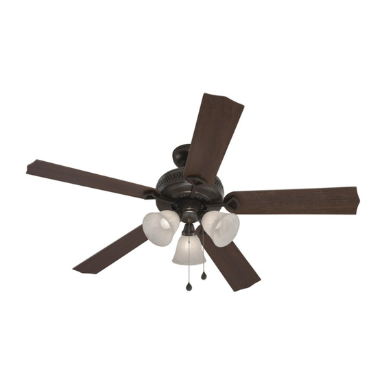
BARNSTAPLE BAY
CEILING FAN
MODEL #RLG52NWZ5C3L
Lowes.com/harborbreeze
ITEM #0593742
0648637
0648638
RLG52WW5C3L
RLG52BNK5C3L
Español p. 20
4007498
Advertisement
Table of Contents

Related Manuals for Harbor Breeze RLG52NWZ5C3L


Summary of Contents for Harbor Breeze RLG52NWZ5C3L
-
Page 1: Ceiling Fan
ITEM #0593742 0648637 0648638 BARNSTAPLE BAY CEILING FAN Harbor Breeze® is a registered trademark of LF, LLC. All Rights Reserved. MODEL #RLG52NWZ5C3L RLG52WW5C3L RLG52BNK5C3L Español p. 20 4007498 ATTACH YOUR RECEIPT HERE Serial Number Purchase Date Questions, problems, missing parts? Before returning to your retailer, call our customer service department at 1-800-643-0067, 8 a.m. -
Page 2: Table Of Contents
TABLE OF CONTENTS Safety Information ........................2 Package Contents ........................4 Hardware Contents ...........................5 Preparation ...........................5 Initial Installation ........................5 Downrod-Style Fan Mounting ....................7 Closemount-Style Fan Mounting ..................9 Wiring ...........................11 Final Installation ........................13 Operating Instructions .......................15 Care and Maintenance ......................17 Troubleshooting........................17 Limited Lifetime Warranty ....................19 Replacement Parts List .......................19 SAFETY INFORMATION READ AND SAVE THESE INSTRUCTIONS... - Page 3 SAFETY INFORMATION DANGER When using an existing outlet box, make sure the outlet box is securely attached to the building structure and can support the full weight of the fan. Failure to do this can result in serious injury or death.
-
Page 4: Package Contents
PACKAGE CONTENTS PART DESCRIPTION PART DESCRIPTION QUANTITY QUANTITY Balancing Kit Downrod Pin (preassembled) Canopy Clip (preassembled) Mounting Bracket Bulb Motor Housing Canopy Mounting Screw Lock Washer (preassembled) (preassembled) Switch Housing Screw Light Kit Fitter (preassembled) Blade Blade Arm IMPORTANT: You must use the parts provided Glass Shade with this fan for proper installation and safety. -
Page 5: Hardware Contents
HARDWARE CONTENTS (shown actual size) Blade Blade Screw Washer Wire Qty. 15 Connector Qty. 15 + 1 extra + 1 extra Qty. 4 Pull Chain Extension Qty. 2 PREPARATION Before beginning assembly of product, make sure all parts are present. Place motor on carpet or on foam to avoid damage to finish. - Page 6 INITIAL INSTALLATION 2. Determine mounting method to use. A. Downrod mount (standard or angled ceiling) B. Closemount (standard ceiling only) 19° max. IMPORTANT: If using the angle mount, ensure the ceiling angle is not steeper than 19°. *Helpful Hint: Downrod-style mounting is best suited for ceilings 8 ft.
-
Page 7: Downrod-Style Fan Mounting
INITIAL INSTALLATION Secure mounting bracket (C) to outlet box (not STANDARD ANGLE MOUNT included) using screws, spring washers and flat MOUNT washers provided with the outlet box. *NOTE: It is very important you use the proper hardware when installing the mounting bracket (C) as this will support the fan. - Page 8 DOWNROD-STYLE FAN MOUNTING 2. Insert downrod (A) through canopy (B). Thread wires from motor housing (D) up through downrod (A). Slip downrod (A) into motor housing yoke, align holes and re-install pin (L) and clip (M). Tighten set screws in motor housing yoke and then tighten preassembled nuts on the set screws.
-
Page 9: Closemount-Style Fan Mounting
DOWNROD-STYLE FAN MOUNTING If you decided to cut back the lead wires in Step 4, strip 1/2 in. of insulation from end of each wire -- white, black, green and blue (if applicable). Twist stripped ends of each strand of wire within the insulation with pliers (not included). - Page 10 CLOSEMOUNT-STYLE FAN MOUNTNG Remove every other preassembled screw and lock washer from top of motor housing (D). Screw Washer Pull wires up through hole in the middle of the canopy (B) and attach canopy (B) to motor Screw housing (D) using the three previously removed Washer screws and lock washers.
-
Page 11: Wiring
WIRING WARNING: To reduce the risk of fire, electrical shock or personal injury, wire connectors provided with this fan are designed to accept only one 12-gauge house wire and two lead wires from the fan. If your house wire is larger than 12-gauge or there is more than one house wire to connect to the corresponding fan lead wires, consult an electrician for the proper size wire connectors to use. - Page 12 WIRING 1b. FAN CONTROLLED BY PULL CHAIN, LIGHT FAN CONTROLLED BY PULL CHAIN, LIGHT BY WALL SWITCH FAN AND LIGHT CONTROLLED BY TWO WALL SWITCHES BY WALL SWITCH: Connect BLACK wire from fan to BLACK wire from ceiling. Connect BLUE wire from fan to the BLACK (or RED) wire from the 120V POWER FROM CEILING...
-
Page 13: Final Installation
FINAL INSTALLATION 1. Lift canopy (B) to mounting bracket (C) again, aligning slotted holes in canopy (B) with loosened Closemount canopy mounting screws (O) in mounting bracket Downrod Option Option (C). Twist canopy (B) clockwise to lock. Re-insert the two previously removed canopy mounting screws (O) and lock washers (E) (Step 4a, page 6) and tighten all canopy mounting screws (O) securely. - Page 14 FINAL INSTALLATION Remove the three preassembled switch housing screws (P) from light kit fitter (F). Locate the BLUE (or BLACK) and WHITE wires in the switch housing preassembled on motor housing (D) that are labeled FOR LIGHT and remove plastic from these two wires.
-
Page 15: Operating Instructions
FINAL INSTALLATION Install bulbs (N). IMPORTANT: When you need to replace bulbs, please allow the bulb(s) and glass shade(s) to cool down before touching them. 8. Attach pull chain extensions (DD) or custom pull chain extensions (not included) to corresponding fan and light pull chains. - Page 16 OPERATING INSTRUCTIONS 2. The light pull chain, located in the middle, is used to turn the lights ON or OFF. 3. Use the fan reverse switch, located on the Reverse Switch switch housing, to optimize your fan for seasonal performance. A ceiling fan will allow you to raise your thermostat setting in summer and lower your thermostat setting in winter without feeling a difference in your comfort.
-
Page 17: Care And Maintenance
OPERATING INSTRUCTIONS 3C. IMPORTANT: Reverse switch must be set either completely UP or completely DOWN for fan to function. If the reverse switch is set in the middle position, fan will not operate. CARE AND MAINTENANCE At least twice each year, lower canopy (B) to check downrod (A) assembly, and then tighten all screws on the fan. - Page 18 TROUBLESHOOTING PROBLEM POSSIBLE CAUSE CORRECTIVE ACTION Excessive 1. Blades are loose. 1. Tighten all blade screws. wobbling. 2. Blade arms incorrectly attached. 2. Re-install blade arms. 3. Unbalanced blades. 3. Switch one blade with a blade from the opposite side or use balancing kit (K).
-
Page 19: Limited Lifetime Warranty
0648637-B1 0648638-B1 0593742-B1 Mounting Bracket 0648637-C1 0648638-C1 0593742-C1 Light Kit Fitter 0648637-F 0648638-F 0593742-F Blade 0648637-G 0648638-G 0593742-G Blade Arm 0648637-H 0648638-H 0593742-H Printed in China Harbor Breeze® is a registered trademark of LF, LLC. All Rights Reserved. Lowes.com/harborbreeze KHLI1608...
Need help?
Do you have a question about the RLG52NWZ5C3L and is the answer not in the manual?
Questions and answers