
Subscribe to Our Youtube Channel
Related Manuals for GW Instek GPS-S Series


Summary of Contents for GW Instek GPS-S Series
- Page 1 sales@artisantg.com artisantg.com (217) 352-9330 | Click HERE Find the Instek GPS-3030DD at our website:...
- Page 2 DC POWER S U P P L Y GPS-S SERIES (ANALOG 1 DIGITAL TYPE) User Manual ISO-9001 CER TIFIED MANUFACTURER Artisan Technology Group - Quality Instrumentation ... Guaranteed | (888) 88-SOURCE | www.artisantg.com...
-
Page 3: Table Of Contents
CONTENTS SECTION PAGE INTRODUCTION ........................SPECIFICATIONS General 2-2 Constant Voltage Operation 2-3 Constant Current Operation ........................2-4 Indicator Meter 2-5 Insulation ......................THEORY OF OPERATION PANEL CONTROLS AND INDICATORS 4-1 Front Panel 4-2 Rear Panel OPERATION INSTRUCTIONS 5-1 Precaution ......................5-2 Setting Current Limit 5-3 Constant Voltage/Constant Current Characteristic ........................ -
Page 4: Specifications
SPECIFICATIONS 2-1 General Main supply Rating, dimension and weight see Table 2-1. Table 2-1 Max. Rating Input Rating FUSE Type and Rating Weight MODEL Volts (V) Watts 1 00v1120v Amps (A) GPS-1830 2A 250V 2A 250V T 1.25A 250V GPS-1850 T 2.5A 250V T 2.5A 250V T 1.25A 250V... -
Page 5: Constant Voltage Operation
Operation Temperature & Humidity Storage Temperature & -10°C to 70"C, <70% Humidity Accessories ..................Test Lead (current ....................Operation Manual Constant Voltage Operation line regulation<O.O1%+3mV. load regulation~O.O1%+3mV (rating current~3A). load regulation~O.O1%+5mV (rating current>3A). (3) Recovery time<IOOps (50% Load change, minimum load 0.5A) (4) Ripple Noise ~0.5mVrms (5Hz-1MHz) (rating current~3A). -
Page 6: Insulation
Voltage range: Current range: (2) Analog Type Meter: Voltmeter and Ammeter each one. Class: 2.5 Dimensions: 50x50 m/m. Insulation Between chassis and output terminal. Between chassis and AC cord. 30MR or above (DC500V). THEORY OF OPERATION The power supply consists of an AC input circuit and transformer, a bias supply consisting of a rectifier and filter and reference voltage source, a main regulator circuit consisting of the main rectifier and filter, a series regulator, a current comparator, a voltage comparator, a reference voltage amplifier, a remote control and a relay control circuit. - Page 7 AC INPUT AUXILIARY REFERENCE RECTIFIER AND VOLTAGE FILTER D l 0 2 1 SOURCE REMOTE CONTROL MAIN RELAY R EFE RE N C E RECTIFIER CONTROL DRIVER AMP CURRENT COMPARATOR MASTER O/P SERIES CURRENT COMPARATOR REGULATOR U 1 0 5 9101,9102 CURRENT VOLTAGE...
-
Page 8: Panel Controls And Indicators
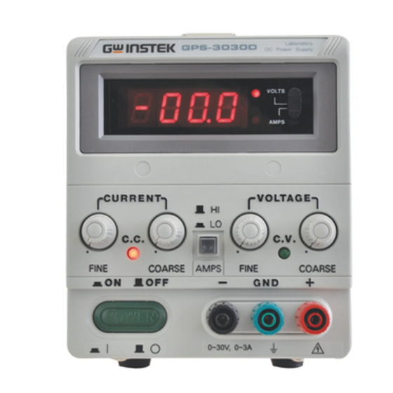
PANEL CONTROLS AND INDICATORS Front panel CV indicator lights when the power turn on and constant voltage operation. CC indicator lights when this unit in constant current operation. Voltage coarse for the coarse adjustment of the output voltage. Voltage fine for the fine adjustment of the output voltage. - Page 9 LABORATORY DC POWER SUPPLY / FIN COARSE COARSE Fig. 4-1 Front Panel (Digital Type) Artisan Technology Group - Quality Instrumentation ... Guaranteed | (888) 88-SOURCE | www.artisantg.com...
-
Page 10: Rear Panel
FIG. 4-3 REAR PANEL Artisan Technology Group - Quality Instrumentation ... Guaranteed | (888) 88-SOURCE | www.artisantg.com... -
Page 11: Operation Instructions
OPERATION INSTRUCTIONS Precaution AC input AC input should be within the range of line voltage 10% 50160Hz WARNING. To avoid electrical shock, the power cord protective grounding conductor must be connected to ground. (2) Installation Avoid using the supply in a place where ambient temperature exceeds 40°C. The heat sink located at the rear of the supply must have sufficient air space for radiation. - Page 12 Vo Max -Crossover Point Output Voltage Output Current Fig. 5-1 Constant VoltageIConstant Current Characteristic. A good example of this would be seen when charging a 12-volt battery. Initially, the open circuit voltage of the power supply may be preset for 13.8 volts. A low battery will place a heavy load on the supply and it will operate in the constant current mode, which may be adjusted for a 1 amp charging rate.
-
Page 13: Operation Mode
Operation Mode Single Operation Use the supply as it is for single operation. A. Set Power switch to "OFF" position. B. Make sure that line voltage is correct for the input power voltage. C. Plug power cord into the power outlet. D. - Page 14 REAR PANEL SER. POWER (MASTER) LOAD CONNECTED 0 0 0 0 POWER SUPPLY (SLAVE) Fig. 5-2 Coilllectillg Two Power Supplies in Series Artisan Technology Group - Quality Instrumentation ... Guaranteed | (888) 88-SOURCE | www.artisantg.com...
- Page 15 E. Set the SLAVE VOLTAGE and CURRENT control t o maximum output. F. When connected in series, from the master VOLTAGE controls of each power supply exercise control over 0 to rating range. Add the t w o voltmeter readings together t o determine the total output voltage, or an external voltmeter may be connect across the load.
- Page 16 REAR PANEL CONNECTED POWER SUPPLY Fig. 5-3 Connecting Two Power Supplies in Parallel. Artisan Technology Group - Quality Instrumentation ... Guaranteed | (888) 88-SOURCE | www.artisantg.com...
- Page 17 (4) Remote control of output voltage The output voltage of the power supply can be remote-controlled with an external voltage, the connection scheme as follow, See Fig. 5-4. Fig. 5-4 REAR PANEL REMOTE CONTROL VOLTAGE SOURCE POWER SUPPLY Set the power supply INT-SLAVE switch to "SER-SLAVE" position. B.
- Page 18 (5) Remote control of output current See Fig. '5-5. Fig. 5-5 REMOTE CONTROL VOLTAGE SOURCE POWER A. Set the power supply INT-SLAVE switch to "PAR-SLAVE" position. line of control voltage source is connected to the "PAR B. The input terminal and the line of control voltage source connected the power supply output...
-
Page 19: Fuse Replacement
MAINTENANCE The following instructions.are for use by qualified personnel only. To avoid electrical shock, do not perform any servicing other than contained in the operating instructions unless you are qualified to do so. Fuse Replacement If the fuse blows, the C V or C C indicators will not light and the power supply will not operate. The fuse should not normally open unless a problem has developed in the unit. -
Page 20: Cleaning
If readjustment is required, use the following procedure. Locations of the adjustments are shown in Fig. 6-1 and Fig. 6-2. Adjustment of the Rating Voltage A. Connect an accurate (f0.1%) external multimeter to measure the dc voltage at output terminals of the power supply. C. - Page 21 MAX. GPS-846 -1 GPS-846 -2 GPS-846 -7 VR 109 GPS-846 -6 MAX. VOLTS. Fig. 6-1 Adjustment Location Fig. 6-2 Adjustment Location Artisan Technology Group - Quality Instrumentation ... Guaranteed | (888) 88-SOURCE | www.artisantg.com...
Need help?
Do you have a question about the GPS-S Series and is the answer not in the manual?
Questions and answers