Table of Contents

Related Manuals for Karma KM-8522 Series


Summary of Contents for Karma KM-8522 Series
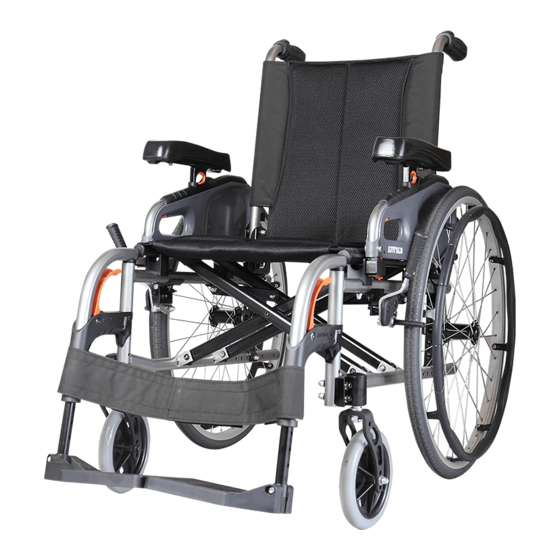
- Page 1 Manual Wheelchair Maintenance Manual KM-8022/KM-8522 series...
- Page 2 Part section and Part Number Part Name/Description Quantity required 4. Warranty Policy- Do use the parts Karma provides to meet the requirement of product quality and warranty policy. For more detail, please refer to user manual / distribution contract 5.
- Page 3 5.3 Limited Loading Weight: 130KG 6. Accessories Footrest: Amputee support / 90 degree footrest/ Footrest extension kit Footplate: Angle adjustable footplate / Aluminum footplate Others: Multi-function safety / Backrest bag / Lateral backrest support bar / Tension adjustable backrest upholstery / Tension adjustable seat upholstery / Net sack /1”,2”Seat depth extension tube”(should adapt Footrest extension kit ) / IV Pole/ Oxygen tank holder/...
-
Page 4: Table Of Contents
TABLE OF CONTENTS 1. Instructions of Replacement --------------------------------------------------------------------- 1 1.1 Backrest --------------------------------------------------------------------------------------- 1 1.2 Armrest --------------------------------------------------------------------------------------- 2 1.3 Footrest --------------------------------------------------------------------------------------- 5 1.4 Brake ------------------------------------------------------------------------------------------ 8 1.5 Frame ---------------------------------------------------------------------------------------- 10 1.6 Wheels --------------------------------------------------------------------------------------- 11 1.7 Rear Wheel Assembly ----------------------------------------------------------------------- 12 1.8 Casters --------------------------------------------------------------------------------------- 13 2. -
Page 5: Instructions Of Replacement
1. Instructions of Replacement 1.1 Backrest 1.1.1 Backrest Frame Figure 1.1.1 1. Backrest Tube Sleeve 2. M6 Flat Washer 3. Hex Nylon Dome Nut 4. Button Head Cap Screw M6*45L 5. Button Head Cap Screw M6*50L 6. Backrest Push Handle Tube-Lengthened 7. -
Page 6: Backrest
Removal and Replacement: 1.1.1.1Use 4 mm L-shape Allen Key and 10 mm open end wrench to loosen part 4 and 5. 1.1.1.2 Remove part 6. 1.1.1.3Re-assembly is done in reverse order. Key Inspection: ● Make sure all screws are properly tightened. 1.1.2 Backrest Upholstery Figure 1.1.2 1. -
Page 7: Armrest
1.2 Armrest 1.2.1 Flip-Back Armrest Figure 1.2.1 1. Flip-back Elevating Armrest Assembly 2. M8 Socket Head Cap Screw 3. 7/8" Plastic Arc Washer 4. Armrest Clamp Bushing 5. M8 Flat Washer 6. M8 Spring Washer 7. M8 Hex Nylon Dome Nut Tools: - 13 mm open end wrench X 2 Removal and Replacement:... - Page 8 1.2.2 Side Panel Assembly Figure 1.2.2 1. Screw Binding Post Set 2. M6 Plastic Washer 3. Side Panel Positioning Part 4. Side Panel Lock 5. Spring Pin 6. Truss Phillips Tapping Screw 7. Armrest Elevating Bracket Tools: - 4 mm L-shape Allen Key x2 - Philips Screwdriver -Φ6 Rod - Hammer...
- Page 9 1.2.3 Height Adjustable Armrest Assembly Figure 1.2.3 1. Ergo Armrest 2. Gold Trigger Elevating Armrest 3. M5 Flat Washer 4. M5 Spring Washer 5. M5 Button Head Cap Screw Tools: - 3 mm L-shape Allen Key Removal and Replacement: 1.2.3.1 Use 3 mm L-shape Allen Key to loosen part 5. Remove part 1 and part 2. 1.2.3.2 Re-assembly is done in reverse order.
-
Page 10: Footrest
1.3 Footrest 1.3.1 Footplate Figure 1.3.1 1. Grip Footrest 2. M6 Hex Nylon Dome Nut 3. M6 Hex Socket Head Cap Screw 4. Footplate Tools: -4 mm L-shape Allen Key - 10 mm open end wrench Removal and Replacement: 1.3.1.1 Use 4 mm L-shape Allen Key and 10 mm open end wrench to loosen part 2 and part 3. 1.3.1.2 Remove part 4. - Page 11 1.3.2 Grip Footrest Figure 1.3.2 1. Grip Footrest 2. Y-shaped Tube Plug 3. M6 Hex Socket Head Cap Screw Tools: -4 mm L-shape Allen Key Removal and Replacement: 1.3.2.1 Use 4 mm L-shape Allen Key to loosen part 2. 1.3.2.2 Remove part 3. 1.3.3.3 Re-assembly is done in reverse order.
- Page 12 1.3.3 Footplate Figure 1.3.3 1. Footplate Tube 2. Sleeve 3. 1/4" Nylon Lock 4. 1/4" Hex Socket Head Cap Screw 5. Footplate Tools: -5 mm L-shape Allen Key Removal and Replacement: 1.3.2.1 Use 5 mm L-shape Allen Key to loosen part 3 and part 4. 1.3.2.2 Remove part 5.
-
Page 13: Brake
1.4 Brake Figure 1.4 1. M6 Hex Nylon Dome Nut 2. M6 Spring Washer 3. M5 Button Head Cap Screw 4. M5 Flat Washer 5. Brake 6. Brake Cable Bolt 7. Brake Cable 8. M6 Hex Nylon Dome Nut 9. M5 Button Head Cap Screw Tools: -4 mm L-shape Allen Key - 8 mm open end wrench... - Page 14 Removal and Replacement: 1.4.1 Use 8 mm open end wrench to loosen part 1. 1.4.2 Remove part 7. 1.4.3 Use 4 mm L-shape Allen Key and 10 mm open end wrench to loosen part 3 and part 8. 1.3.4 Remove part 5. 1.3.5 Re-assembly is done in reverse order.
-
Page 15: Frame
1.5 Frame Figure 1.5 1. Side Frame 2. M6 Button Head Cap Screw 3. M6 Flat Washer 4. M6 Nylon Lock 5. M8 Button Head Cap Screw 6. M8 Plastic Washer 7. M8 Nylon Lock 8. Cross Bar-Slide Groove Type Tools: -4 mm L-shape Allen Key -5 mm L-shape Allen Key... -
Page 16: Wheels
1.6 Wheels Figure 1.6 1. Rear Wheel Assembly 2. Quick release axle 3. Caster Bracket Dust Cover 4. Nylon Lock Nut 5. 1/2" Flat Washer 6. Caster Tools: - 19 mm socket wrench Removal and Replacement: 1.6.1 Press part 2 and pull out part 1 from the side frame. 1.6.2 Remove part 3. -
Page 17: Rear Wheel Assembly
1.7 Rear Wheel Assembly Figure 1.7 1. Tire 2. Nylon Lock 3. Rear Wheel Rim 4. Ergo Rear Wheel 5. M5 Flat Washer 6. Phillips Round Head Screw Tools: -8 mm open end wrench -Tire spoon *2 - Philips screwdriver Removal and Replacement: 1.7.1 Use two tire spoons, one for either side of part 1, to remove part 1. -
Page 18: Casters
1.8 Casters Figure 1.8 1. Long Vigor Fork 2. M8 Flat Washer 3. M8 Hex Nylon Dome Nut 4. Bearing 5. Caster 6. Caster Sleeve Tools: - 13 mm open end wrench *2 Removal and Replacement: 1.8.1 Use two 13mm open end wrench to loosen part 3 and part 7. 1.8.2 Remove part 5. -
Page 19: Instructions Of Replacement For Optional Devices
2. Instructions of Replacement for Optional Devices 2.1 Anti-Tipper Figure 2.1 1. Anti-tipper Assembly 2. Screw Binding Post Set 3. M6 Button Head Cap Screw 4. M6 Nylon Lock Tools: - 10 mm open end wrench - 4 mm L-shape Allen Key *2 Removal and Replacement: 2.1.1 Use 4 mm L-shape Allen Key and 10mm open end wrench to loosen part 3 and part 4. -
Page 20: Tie Down Hook
2.2 Tie Down Hook Figure 2.2 1. M8 Nylon Lock 2. M8 Flat Washer 3. Sleeve 4. M8 Button Head Cap Screw 5. Hook 6. M6 Flat Washer 7. M6 Button Head Cap Screw 8. Hook 9. Washer 10. M6 Nylon Lock Tools: - 10 mm open end wrench - 13 mm open end wrench... -
Page 21: Oxygen Tank Holder
2.3 Oxygen Tank Holder Figure 2.3 1. Oxygen Tank Holder 2. M6 Hex Socket Head Cap Screw 3. Brake Clamp- Untapped 4. Brake Clamp-Tapped 5. Oxygen holder bracket 6. Hook for Oxygen Cylinder 7. PinΦ8 w/ Pull Ring Tools: - 5 mm L-shape Allen Key Removal and Replacement: 2.3.1 Pull part 7 out. -
Page 22: Pole Assembly
2.4 IV Pole Assembly Figure 2.4 1. Hook 2. Phillips Button Tapping Screw 3. IV Pole Assembly 4. M6 Hex Socket Head Cap Screw 5. M6 Nylon Lock Tools: - 5 mm L-shape Allen Key -Philips Screwdriver Removal and Replacement: 2.4.1 Use Philips screwdriver to loosen part 2. -
Page 23: Walking Stick Box Assembly
2.5 Walking Stick Box Assembly Figure 2.5 1. Phillips Button Tapping Screw 2. Walking Stick Velcro Fix Strap 3. Walking Stick Box Assembly 4. M6 Hex Socket Head Cap Screw 5. Brake Clamp-Untapped 6. Brake Clamp-Tapped Tools: - 5 mm L-shape Allen Key - Philips screwdriver Removal and Replacement: 2.5.1 Use Philips screwdriver to loosen part 1. -
Page 24: Lateral Support Assembly
2.6 Lateral Support Assembly Figure 2.6 1. M6 Hex Socket Head Cap Screw 2. M6 Flat Washer 3. Nut 4. Lateral Support Assembly Tools: - 4 mm L-shape Allen Key Removal and Replacement: 2.6.1 Use 4 mm L-shape Allen Key to loosen part 1. 2.6.2 Remove part 4. -
Page 25: Hemi Armrest Assembly
2.7 Hemi Armrest Assembly Figure 2.7 1. Hemi Armrest 2. M8 Hex Nut 3. M6 Flat Washer 4. M5 Hex Socket Head Cap Screw 5. Pin 6. M6 Hex Nylon Dome Nut 7. M6 Hex Socket Head Cap Screw Tools: - 3 mm L-shape Allen Key - 6 mm L-shape Allen Key - 10 mm open end wrench... - Page 26 Removal and Replacement: 2.7.1 Use 3 mm L-shape Allen Key to loosen part 4. 2.7.2 Part 1 can be removed or adjusted. 2.7.3 Use 4 mm L-shape Allen Key and 10 mm open end wrench to loosen part 7 and part 6. 2.7.4 The location of part 1 can be adjusted.
-
Page 27: Elevating & Swing Away Footrest
2.8 Elevating & Swing Away Footrest Figure 2.8 1. M8 Hex Nylon Dome Nut 2. M6 Hex Nut 3. M5 Spring Washer 4. M5 Hex Socket Head Cap Screw 5. M5 Flat Washer 6. Mounting Plate 7. M8 Flat Washer 8. - Page 28 Removal and Replacement: 2.8.1 Use 3 mm L-shape Allen Key to loosen part 4. 2.8.2 Remove or adjust part 9. 2.8.3 Use 6 mm L-shape Allen Key to loosen part 8. 2.8.4 The location of part 6 can be adjusted. 2.8.5 Re-assembly is done in reverse order.
-
Page 29: Stump Footrest
2.9 Stump Footrest Figure 2.9 1. Calf Pad 2. M6 Hex Nut 3. M6 Hex Nylon Dome Nut 4. M5 Flat Washer 5. M5 Spring Washer 6. M5 Hex Socket Head Cap Screw 7. M6 Flat Washer 8. M6 Hex Socket Head Cap Screw Tools: - 3 mm L-shape Allen Key - 4 mm L-shape Allen Key... - Page 30 Removal and Replacement: 2.9.1 Use 3 mm L-shape Allen Key to loosen part 6. 2.9.2 Part 1 can be removed or adjusted. 2.9.3 Use 4 mm L-shape Allen Key and 10 mm open end wrench to loosen part 8 and part 3. 2.9.4 The location of part 1 can be adjusted.
-
Page 31: Vertical Swing-Away Footrest
2.10 Vertical Swing-Away Footrest Figure 2.10 1. M6 Flat Washer 2. M6 Hex Socket Head Cap Screw 3. M6 Hex Socket Head Cap Screw 4. Heel Loop 5. M8 Flat Washer 6. M6 Hex Nylon Dome Nut 7. Angle and Depth Adjustable Footrest 8. - Page 32 Tools: - 4 mm L-shape Allen Key - 10 mm open end wrench Removal and Replacement: 2.10.1 Use 4 mm L-shape Allen Key and 10 mm open end wrench to loosen part 2 and part 6. 2.10.2 Part 11 can be removed or adjusted. 2.10.3 Use 4 mm L-shape Allen Key and 10 mm open end wrench to loosen part 3 and part 6.
-
Page 33: Angle And Depth Adjustable Footrest
2.11 Angle and Depth Adjustable Footrest Figure 2.11 1. M6 Flat Head Socket Cap Screw 2. Footplate 3. Angle and Depth Adjustable Footrest 4. Adjustable Footplate Base 5. M6 Hex Nylon Dome Nut 6. M10 Hex Socket Head Cap Screw 7. -
Page 34: Drum Brake
2.12 Drum Brake Figure 2.12 1. Brake Cable 2. Rear Wheel Tools: - 10 mm open end wrench Removal and Replacement: 2.12.1 Use 10 mm open end wrench to loosen the nut below part 2 2.12.2 Remove part 1. 2.12.3 Re-assembly is done in reverse order. Key Inspection: ●... -
Page 35: Adjustable Backrest Tube
2.13 Adjustable Backrest Tube Figure 2.13 1. Adjustable Backrest Push Handle Tube 2. M5 Flat Washer 3. M5 Button Head Cap Screw 4. Adjustable Backrest Lower Tube 5. M5 Nylon Lock Tools: - 4 mm L-shape Allen Key - 8 mm open end wrench Removal and Replacement: 2.11.1 Use 4 mm L-shape Allen Key and 8 mm open end wrench to loosen part 3 and part 5. -
Page 36: Instructions Of Adjustment
3. Instructions of Adjustment 3.1 Adjusting Seat Height for Wheelchair Equipped with 20, 22 or 24 Inch Rear Wheels Caster Position Rear Wheel Position Anti-Tipper Position (For457 ㎜(18")~533 ㎜(21")seat height) Seat Caster Size Rear Wheel Caster Rear Wheel Seat Anti-Tipper Height Caster Position Size... - Page 37 Caster Position Rear Wheel Position ( Anti-Tipper Position (For 304 ㎜(15.5")~457 ㎜ (18" )seat height) Seat Caster Size Rear Wheel Caster Rear Wheel Seat Angle Anti-Tipper Height Caster Position Size Bracket Position Position 5.5〫 6" 5" 22" 5.3〫 457 ㎜ 5.1〫...
- Page 38 Caster Position Rear Wheel Position Anti-Tipper Position (For 394 ㎜(15.5")~457 ㎜(18") seat height) Seat Caster Size Rear Wheel Caster Rear Wheel Seat Angle Anti-Tipper Height Caster Position Size Bracket Position Position 4.0〫 5" 22" 3.8〫 394 ㎜ 3.7〫 (15.5") 4.0〫 5"...
-
Page 39: Seat Height Adjustment For Wheelchair Equipped With 14 Inch Rear Wheels
3.2 Seat Height Adjustment for Wheelchair Equipped with 14 inch Rear Wheels Caster Position Rear Wheel Position Caster Size Caster Seat Rear Wheel Rear Wheel Seat Caster Position Bracket Height Size Posotion Angle 508 ㎜ 8" 7” 14" 8.5〫 (20") 483 ㎜... -
Page 40: Caster Adjustment For Wheelchair Equipped With 20, 22 Or 24 Inch Rear Wheels
3.3 Caster Adjustment for wheelchair Equipped with 20, 22 or 24 Inch Rear Wheels Rear Wheel Position Eccentric Hex Spacer Direction of Eccentric Hex Spacer Direction of Rear Seat Rear Wheel Eccentric Hex Caster Size Wheel Height Size Spacer Bracket Right Left 533 ㎜... - Page 41 Rear Wheel Position Eccentric Hex Spacer Direction of Eccentric Hex Spacer Direction of Seat Rear Wheel Rear Wheel Caster Size Eccentric Hex Height Size Bracket Spacer 6" 5" 22" 457 ㎜ (18") 6" 5" 20" 5" 22" 432 ㎜ (17") 5"...
- Page 42 Rear Wheel Position Eccentric Hex Spacer Direction of Eccentric Hex Spacer Direction of Rear Wheel Rear Wheel 座高 Caster Size Eccentric Hex Size Bracket Spacer 5" 22" 394 ㎜ (15.5") 5" 20"...
-
Page 43: Caster Adjustment For Wheelchair Equipped With 14 Inch Rear Wheels
3.4 Caster Adjustment for Wheelchair Equipped with 14 inch Rear Wheels Rear Wheel Bracket Eccentric Hex Spacer Direction of Eccentric Hex Spacer Direction of Seat Rear Wheel Rear Wheel Caster Size Eccentric Hex Height Size Bracket Spacer 508 ㎜ 8" 14"... - Page 44 Rev:00 2015.11 ...
Need help?
Do you have a question about the KM-8522 Series and is the answer not in the manual?
Questions and answers