
Subscribe to Our Youtube Channel
Related Manuals for Pfeiffer DuoLine DUO 20 M


Summary of Contents for Pfeiffer DuoLine DUO 20 M
- Page 1 Betriebsanleitung • Operating Instructions DuoLine™ Rotary Vane Pumps DUO 20 M DUO 20 MC...
-
Page 2: Table Of Contents
Table of contents Table of contents About this manual........3 Validity. -
Page 3: About This Manual
1 About this manual 1.1 Validity This operating manual is for customers of Pfeiffer Vacuum. It describes the func- tioning of the designated product and provides the most important information for safe use of the unit. The description follows applicable EU guidelines. All informa- tion provided in this operating manual refer to the current state of the product's de- velopment. - Page 4 About this manual Pictograph Prohibition of an action or activity in connection with a definitions source of danger, the disregarding of which may result in serious accidents. Warning of a displayed source of danger in connection with operation of the unit or equipment. Command to perform an action or task associated with a source of danger, the disregarding of which may result in serious accidents.
-
Page 5: Safety
• The vacuum pump may only be used to generate a vacuum. • Installation, operating and maintenance regulations must be complied with. • Other accessories than those described in this manual must not be used without the agreement of Pfeiffer Vacuum. -
Page 6: Improper Use
• Use of the vacuum pump to generate pressure. • Pumping of liquids. • The use of operating fluids not specified by Pfeiffer Vacuum. • Connection to pumps or units which are not suitable for this purpose according to their operating instructions. -
Page 7: Transport And Storage
Transport and Storage 3 Transport and Storage 3.1 Transport Transport instructions Remove the locking cap from the vacuum and exhaust flange immediately be- fore connecting! – Check the protective strainer, paying attention to the o-ring. Use only the handle or the crane eye on the top side of the pump to lift the pump. –... -
Page 8: Product Description
Product description 4 Product description 4.1 Product identification To correctly identify the product when communicating with Pfeiffer Vacuum, al- ways have the information from the rating plate available and use it: • Pump model and model number • Serial number •... -
Page 9: Function
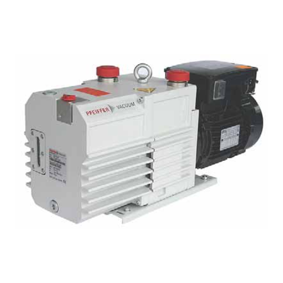
Product description 4.2 Function ® The vacuum pumps of the DuoLine are dual stage rotary vane pumps and are used primarily for rough and medium vacuum applications. The pumps are fitted with a hydraulically controlled vacuum safety valve which, when the pump is at a stillstand, closes the vacuum chamber vacuum tight and at the same time vents the pump. -
Page 10: Installation
Installation 5 Installation 5.1 Setting up the pump Installation location Observe the following requirements when setting up the pump: • Note the load-bearing capacity of the mounting surface. • Maximum installation altitude 2000 m (above mean sea level) • Permissible ambient temperature: +12 ... +40°C •... -
Page 11: Connecting The Exhaust Side
Installation 5.3 Connecting the exhaust side CAUTION High pressure in the exhaust line! Danger of damage to the seals and danger of the pump bursting. Install the line without shut-off valves on the exhaust side. If there is danger of a build-up of excess pressure (> 1500 mbar abs.) in the lines, observe all official accident prevention safety regulations. - Page 12 Installation WARNING Danger of injury from moving parts! After power failure or motor shutdown due to overheating, the motor may restart auto- matically. Secure the motor so that it cannot be switched on while any work is being performed on the pump. If necessary, dismantle the pump from the installation for inspection.
- Page 13 Installation Rocker switch in the terminal box for changing the voltage range Switch position: 200 ... 230 V/50 Hz 100 ... 110 V/50 Hz Voltage range: 200 ... 240 V/60 Hz 100 ... 120 V/60 Hz Motor protection To protect the motor in case of malfunction, carry out fuse protection in accor- dance with the regional regulations.
- Page 14 Installation Control voltage OFF button ON button RESET button, external F1 - F3 K1 Contactor F1 ... F4 Fuses T1... T3 PTC resistor sensor H1 Tripping indicator Motor, 3-phase AC 220 ... 240 V Only for devices with two relay outputs Only for MSR type T1...T3 Only for order no.:...
-
Page 15: Filling Up The Operating Fluid
Pumps for special applications (e.g. for pumping corrosive gases) can be operated with other operating fluids. These must be defined in accordance with Pfeiffer Vacuum specifications before initial assembly and ordered separately. Permissible operating fluids • P3 (Standard operating fluid) •... -
Page 16: Operations Monitoring (Option)
Installation 5.6 Operations Monitoring (Option) A pressure switch can be installed on the side of the support to monitor the oil pressure of the rotary vane pump during operations. By pressure drop and when the pump is at rest, the contact of the pressure switch opens. The signal can be used to control external valves. -
Page 17: Operation
Operation 6 Operation 6.1 Before switching on the pump Check the operating fluid level in the sightglass. Compare the voltage and frequency information on the rating plate with the mains voltage and frequency values. Check that the exhaust connection allows free flow (max. permissible pressure 1.5 bar absolute). - Page 18 Set the amount of flushing gas on site. Connect flushing gas at the flushing gas connection. Set flushing gas pressure; maximum pressure 1.5 bar (absolute). – Select the type and amount of flushing gas depending on the process; consult Pfeiffer Vacuum if necessary.
-
Page 19: Switching Off The Pump
Operation 6.4 Switching off the pump The pump can be switched off in any pressure range. Rotary vane pumps have an integrated safety valve on the intake side. If the differ- ential pressure between the exhaust side and the intake side is ≥ 250 mbar, then the valve closes automatically and vents the pump when the pump is switched off. -
Page 20: Maintenance
Maintenance 7 Maintenance 7.1 Precautions WARNING Danger of injury from moving parts! After power failure or motor shutdown due to overheating, the motor may restart auto- matically. Secure the motor so that it cannot be switched on while any work is being performed on the pump. -
Page 21: Changing The Operating Fluid
Check list for inspec- Certain repair and overhaul work should only be performed by Pfeiffer Vacuum Service (PV). Pfeiffer Vacuum will be released from all warranty and liability claims tions, maintenance if the required intervals for inspection, maintenance, or overhaul are exceeded or... - Page 22 Fill up with operating fluid and check the filling level (see p. 15, chap. 5.5). NOTE Request safety data sheets for operating fluids and lubricants from Pfeiffer Vacuum or download them from the Internet. Dispose of operating fluid according to the local regulations.
-
Page 23: Cleaning Or Changing The Silencer
Maintenance 7.3 Cleaning or changing the silencer The silencer 44 is a nozzle inside the pump housing and cannot be altered; when dirty it should either be cleaned or replaced. Dismantling Unscrew 2 cheesehead screws 182 from the gas ballast valve housing. Remove the gas ballast valve housing 42 from the casing 28;... -
Page 24: Shutdown
Visually inspect the inner of the pump before taking it into operation. If there is ev- idence of rust on the parts of the pump which form the housing then do not take it into operation and contact Pfeiffer Vacuum Service. With reference to DIN 7716 and the manufacturer's specifications we recommend replacing the installed elastomer parts after 2 years. -
Page 25: Malfunctions
Malfunctions 9 Malfunctions Please note the following instructions should the pump malfunction: DANGER Strong magnetic field in the vicinity of the drive system! Danger to life for persons with cardiac pacemakers when the drive system is disas- sembled. Persons with cardiac pacemakers must not enter the area of the magnetic field. Disassembled magnetic couplings must be kept away from computers, data storage media and other electronic components. -
Page 26: Troubleshooting
Service if necessary NOTE Service work should only be carried out by qualified personal! Pfeiffer Vacuum is not liable for any damage to the pump resulting from work carried out improperly. Take advantage of our service training programs; additional information at www.pfeiffer-vacuum.net. -
Page 27: Service
Returning contaminated vacuum pumps Units which are microbiologically, explosively or radioactively contaminated will not be accepted by Pfeiffer Vacuum as a matter of principle. Hazardous substances are substances and compounds in accordance with the hazardous goods directive (current version). Should pumps be contaminated or the contamination declara- tion be missing, Pfeiffer Vacuum will decontaminate the pumps at your cost. -
Page 28: Spare Parts
The spare parts packages listed here are only applicable for standard models. Please state all information on the rating plate when ordering spare parts. Other spare parts than those described in this manual must not be used without the agreement of Pfeiffer Vacuum. Spare parts Pump type Revision Article no. - Page 29 Spare parts Exploded view DUO 20 M Rotor Hydraulic pump Pump cylinder Support plate Bearing cover Vanes, rough stage Vanes, medium stage Hydraulic vane Compression spring, vanes (138/ 18 Magnetic coupling, 141/ 2 x 220 148) drive side 2 x 220/ 20 Magnetic coupling, 2 x 208 154/158...
-
Page 30: Accessories
Accessories 12 Accessories Further detailed accessories are contained in the Pfeiffer Vacuum printed Cata- logue or the Online Catalogue. Description Size Number Comments/ (relevant manual) Dust separator STP 025 DN25 ISO-KF PK Z60 106 PK 0120 BN Oil mist filter ONF 25 L... -
Page 31: Technical Data
Technical data 13 Technical data Technical data DUO 20 M DUO 20 MC Flange (in) DN 25 ISO-KF DN 25 ISO-KF Flange (out) DN 25 ISO-KF DN 25 ISO-KF Pumping speed at 50 Hz 20 m 20 m Pumping speed at 60 Hz 24 m 24 m ≤... -
Page 32: Declaration Of Conformity
DIN EN ISO 12100-1/2 EN 294 EN 60335-1, 41 EN 61010 EN 60204 EN 50081-1, -2 EN 1012-2 Signatures: Pfeiffer Vacuum GmbH Berliner Straße 43 35614 Asslar Germany (M.Bender) (Dr. M. Wiemer) CE/2007 Managing Director Managing Director... - Page 33 Roots pumps Dry compressing pumps Leak detectors Valves Components and feedthroughs Vacuum measurement Gas analysis System engineering Service Pfeiffer Vacuum Technology AG · Headquarters/Germany Tel. +49-(0) 64 41-8 02-0 · Fax +49-(0) 64 41-8 02-2 02 · info@pfeiffer-vacuum.de · www.pfeiffer-vacuum.net...
Need help?
Do you have a question about the DuoLine DUO 20 M and is the answer not in the manual?
Questions and answers