Table of Contents
Advertisement
Advertisement
Table of Contents

Related Manuals for DX Engineering DXE-NCC-2


Summary of Contents for DX Engineering DXE-NCC-2
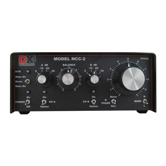
- Page 1 Receive Antenna Phasing Controller DXE-NCC-2 DXE-NCC-2-INS Rev 1b © DX Engineering 2017 1200 Southeast Ave. - Tallmadge, OH 44278 USA Phone: (800) 777-0703 ∙ Tech Support and International: (330) 572-3200 Fax: (330) 572-3279 ∙ E-mail: DXEngineering@DXEngineering.com - 1 -...
-
Page 2: Table Of Contents
Table of Contents Introduction Features Functions and Technical Description Understanding Noise and Interference Reducing Noise and Interference Selecting Antennas Receive Antennas Antenna Polarization Antenna Feedlines Antenna Sensitivity Antenna Bandwidth Combining Antennas to Improve Signal-to-Noise Ratio Use with a Receive Loop or Other Low Noise Antennas Phased Verticals and Beverage Systems Front Panel Controls and Switches Rear Panel Connections... -
Page 3: Introduction
NCC-2 and the Receive Preamp. The NCC-2 is fully compatible with DX Engineering Active Receive Antennas for excellent, low- noise reception from 300 kHz to 30 MHz. A pair of Active Receive Verticals, DXE-ARAV3-2P separated by one-quarter wavelength on the lowest band provides a steerable, optimized unidirectional pattern with a single null. - Page 4 The NCC-2 is also fully compatible with the DX Engineering Active Magnetic Loop; model DXE- RF-PRO-1B, for phasing with a directional low-noise antenna. The NCC-2 can be used with many other combinations of receiving antennas including Single and Reversible Beverage and Beverage On the Ground Antennas, Receive Four-Square and Eight Circle Arrays, K9AY Loops, and more.
-
Page 5: Features
DX Engineering NCC-2 Features RTR system supports phasing a transmit antenna with a separate receive antenna RTR system supports transceivers without a separate receive antenna input Enhanced Phase control – adjusts through 360 degrees within primary design frequency range 500 kHz to 15 MHz. -
Page 6: Functions And Technical Description
NCC-2 Functions and Technical Description The DX Engineering NCC-2 is a multi-purpose two-channel phasing controller that features high signal level handling and very low internal noise. Taking advantage of the time-delay of signal arrival between two antennas spaced by a significant fraction (1/10) of a wavelength or greater, the antenna array creates a directional pattern. - Page 7 NCC-2 Functions and Technical Description (continued) Following the input modules slots, the NCC-2 maintains complete RF isolation between the two channels, beginning with dual, voltage controlled attenuators. They maintain high-stability phasing with low noise receive antennas, as the voltage controlled step attenuators and cross-channel Balance control offers consistent operation for repeatable settings.
- Page 8 In Figure A, the NCC-2 is in MAIN ANT mode or transmit mode, the MAIN ANT IN is internally connected to the RADIO when the power is turned Off. The unit stays in the MAIN ANT mode and the RTR LED goes to Red when: ...
- Page 9 IMPORTANT NOTE: There are three crucial uses of the NCC-2 MAIN ANT OUT: 1. When using the NCC-2 to phase the transmit antenna with a receive antenna, the included BNC patch cable MUST be installed to connect the MAIN ANT OUT into the CH A RX ANT IN.
-
Page 10: Understanding Noise And Interference
Understanding Noise and Interference Before we can use the NCC-2, we need to understand the challenges for operations on HF. Noise limits our ability to hear a weak signal on the lower bands. Noise is often an accumulation of many unwanted signals. -
Page 11: Selecting Antennas
The phasing method of signal enhancement or rejection has several advantages. Interference much stronger than a desired signal can be completely removed without affecting the signal. The NCC-2 can be effective with all types of interference and all modes. ... -
Page 12: Antenna Polarization
The MAIN ANT IN and the RADIO connectors are 50 ohm SO-239 connectors. DX Engineering carries 75 ohm CATV style cable and weather-tight connectors as well as 50 ohm BNC to BNC cable assemblies. 75 ohm antenna systems and feedlines are supported with the optional Internal 50 ohm to 75 ohm Transformer (DXE-IT-PM) module. -
Page 13: Antenna Bandwidth
Antenna Bandwidth Wider bandwidth antennas produce the most stable and reliable performance. Very narrow bandwidth antennas do not work as well. A small resonant loop will be very narrow in response and will shift phase rapidly with frequency changes. This means temperature changes and frequency changes will both require more frequent readjustment of the NCC-2 controls. -
Page 14: Use With A Receive Loop Or Other Low Noise Antennas
The NCC-2 generally works best when both antennas have similar patterns, polarization, and S/N ratios. You may have to experiment to find the best antenna, but successful operation occurs more often with similar antennas. The best system is often found by planning, although it is often worth experimenting. When using any of these directional phased antenna arrays you may record phase settings to null stations from known directions. -
Page 15: Phased Verticals And Beverage Systems
Phased Verticals and Beverage Systems The NCC-2 is an adjustable phasing network that combines two antenna input ports. Antennas can be combined to change or improve directional patterns. Pattern changes can be used to improve signal-to- noise ratio even in the absence of strong noise. It is possible to combine almost any type of receiving antennas into a large array. -
Page 16: Front Panel Controls And Switches
Front Panel Controls and Switches POWER: Turns power ON and OFF. LED is Yellow when the POWER switch is Off but the NCC-2 is connected to an active power supply LED is Green when POWER switch is turned On RTR Switch: When the RTR functionality is used and POWER is LED is Blue with the RADIO PTT line is properly connected to the radio for RX Enable and switch in Norm position LED is RED when radio is in transmit mode and when switched to... - Page 17 Front Panel Controls and Switches (continued) BALANCE: Provides fine adjustment of opposite channel attenuation. It is used to balance or equalize signal levels from CH A and CH B. The BALANCE control provides anywhere from zero to 8 dB attenuation on either A or B. This control has the similar “feel” and operation as the balance controls on conventional stereo systems.
-
Page 18: Rear Panel Connections
Rear Panel Connections MAIN ANT IN: SO-239 connector. Connects to primary transmit antenna. 50 ohm impedance, nominal. This connector goes to a linear amplifier RF Input, if one is used. RADIO: SO-239 connector. Connects NCC-2 to Transceiver. 50 ohm impedance, nominal. -
Page 19: More On Radio Ptt - Rx Enable Failsafe Feature
More On RADIO PTT – RX ENABLE Failsafe Feature The proven design of the RADIO PTT-RX ENABLE failsafe feature used in the RTR-1 and is now improved for the NCC-2 and the RTR-2. In the NCC-2, the purpose of the RTR failsafe circuit is to allow phasing of a transmit antenna and a receive antenna while reducing, to nearly zero, the chances of accidentally transmitting into the phase combiner (the receive side of the NCC-2). -
Page 20: Dxe-Kwd-Rtr Cable Information
The DXE-KWD-RTR is available from DX Engineering. The DX Engineering special RTR to Kenwood cable assembly for Kenwood transceivers adds the shield to the chassis ground connection on the 7-pin DIN shell. Ground On Transmit and RX ENABLE are thereby both functional for the NCC-2, RTR-2 and RTR-1 units with the DXE- KWD-RTR cable. -
Page 21: Internal Jumpers
The NCC-2 has internal jumpers that configure the placement of DC power onto CH A RX ANT IN and CH B RX ANT IN independently. As delivered from DX Engineering, the NCC-2 internal jumpers are positioned for normal operation with no DC power on the antenna input connectors. -
Page 22: Bias Tee Enable
Bias Tee Enable In between the Option 1 and Option 2 areas of both boards there are headers with jumpers labeled “Bias Tee Enable” (one on both the Channel B and Channel A boards. The factory default for these two jumpers is open (NOT jumpered together). For passive receive antennas both of the “Bias Tee Enable”... -
Page 23: Bias Tee Always On
Bias Tee Always On The front panel on the NCC-2 has one header with a jumper labeled “Bias Tee Always On” as shown below. The factory default for this jumper is open - the header pins are NOT connected together). When this jumper is connected (both pins on the header are shorted together with the jumper), Bias Tee voltage is present regardless of transmit and receive keying. -
Page 24: Installation
Installation Please read the following section carefully. The best location for this unit is at the operating position with easy access to the controls since you will be using the S-Meter and listening to your receiver while adjusting the NCC-2. Connections Make connections to the NCC-2 as follows: ... - Page 25 The DX Engineering TVSU-1A programmable sequencer can also be used to provide the proper transmit/receive switching for an amplifier, transceiver, and the NCC-2. Refer to Interconnection Diagram 6 for the high power installation connection diagram. Connect the RADIO jack to a transceiver antenna jack for use on radios that lack a RX ANT IN or the transceiver receive-only antenna port, or receiver antenna input.
-
Page 26: Operation
Operation For two antennas with approximately equal desired signal levels, or for two antennas with approximately equal undesired signals or noise levels. 1. Connect the NCC-2 to your station and a suitable power source. 2. Set the front panel controls as follows: A. -
Page 27: Using The Ncc-2
The PHASE NORM-REV switch will normally turn a NULL point into a PEAK point. Adjust for a null as above, and then reverse the B PHASE switch. Multiple nulls may be found in either switch position depending upon antenna combinations and frequency. ... -
Page 28: Phase Nulling With A Transmit Antenna
J. Change PHASE Norm-Rev to opposite position. The signal should now be strong. Note: Any signal being nulled or peaked must be adjusted to the same level as seen at the receiver from both channels or the NCC-2 Phase Control will not work as expected. Phase Nulling with a Transmit Antenna As described throughout this manual, the primary advantage of using receiving antennas for phase nulling of unwanted signals is to enhance the signal to noise ratio (S/N) of the desired weak signal. -
Page 29: Interconnection Diagrams
Interconnection Diagrams Diagram 1 - Phasing a Transmit Antenna with a single Active Receive Antenna using the RTR function Diagram 1 shows connections for phasing a Transmit antenna signal with a single Active Receive Antenna using the RTR function on a transceiver that does not have a RX ANT INPUT. When the NCC-2 front panel RTR switch is in the Norm position, the RADIO is connected to listen to the phasing of the MAIN ANT and the RX Antenna. - Page 30 Diagram 2 - Phasing a Transmit Antenna with a single Active Receive Antenna not using the RTR function Diagram 2 shows connections for phasing a received signal from a transmit antenna signal that is available at the RX ANT OUT of transceivers so equipped. NCC-2 front panel RTR switch is in the Norm position for the RADIO to listen to the phased combination of the transmit antenna and the CH A receive antenna.
- Page 31 Diagram 3 - Phasing Two Active Receive Antennas not using the RTR function Diagram 3 shows connections for two Active Receive Antennas not using the RTR Main Ant In. Connections are direct phased receive antenna only, fed into RX ANT IN on the transceiver so equipped.
- Page 32 Diagram 4 - Phasing a Transmit Antenna with a single Active Receive Antenna using the RTR function and sharing transmit signals with a SDR Diagram 4 shows connections for phasing a Transmit Antenna with a single Active Receive Antenna using the RTR function and sharing transmit signals with a second receiver. RX ANT IN on transceiver is not used so that an external splitter can share transmit antenna signals with a second receiver for SDR/panadapter display and NCC-2 CHA A RX ANT for simultaneous phased reception on RADIO with the RTR switch in the Norm position.
- Page 33 Diagram 5 - Phasing a Two Active Receive Antennas using the RTR function and Amplifier Diagram 5 shows the connections for a transceiver without RX ANT INPUT. The NCC-2 front panel RTR switch is in the Norm position and connects RADIO to the phasing of only the receive antennas.
- Page 34 Diagram 6 - Phasing dual Active Receive Antennas on a system with a Transmit Antenna, Sequencer and an Amplifier Diagram 6 shows the DXE-NCC-2 for phasing two Active Receive Vertical antennas in a high power transmit system using the RTR function on a transceiver that does not have an RX ANT INPUT.
-
Page 35: Internal Optional Modules
Appendix A Internal Optional Modules The NCC-2 has positions for optional modules (Receiver Guard, Pre Amp, 50-75 ohm Transformer) for each RX ANT CH A and RX ANT CH B. Remove the cover from the NCC-2. Looking at the rear of the unit from the inside, you will see the three Bypass Plug-In boards installed in each channel as shown below. -
Page 36: Removing - Installing Optional Modules Or Bypass Plug-In Boards
Removing - Installing Optional Modules or Bypass Plug-in Boards The NCC-2 has Bypass Plug-In Boards installed at the factory. When installing the optional modules, the Bypass Plug-In boards must be removed. Remove the cover from the NCC-2. Looking at the rear of the unit from the inside, you will see the three Bypass Plug-In boards installed in each channel as shown below. -
Page 37: Specifications
Specifications Useable Frequency Range: 300 kHz to 30 MHz The NCC-2 is primarily designed for 500 kHz to 15 MHz use, although useful operating range extends from below 300 kHz to above 30 MHz. Third Order Output Intercept: +32 dBm each Input, +38 dBm both inputs combined ... -
Page 38: User Notes
User Notes: - 38 -... -
Page 39: User Diagram
User Diagram Use this page to draw in your set up for future reference. - 39 -... -
Page 40: Technical Support
All products manufactured by DX Engineering are warranted to be free from defects in material and workmanship for a period of one (1) year from date of shipment. DX Engineering’s sole obligation under these warranties shall be to issue credit, repair or replace any item or part thereof which is proved to be other than as warranted; no allowance shall be made for any labor charges of Buyer for replacement of parts, adjustment or repairs, or any other work, unless such charges are authorized in advance by DX Engineering.
Need help?
Do you have a question about the DXE-NCC-2 and is the answer not in the manual?
Questions and answers