Table of Contents
Advertisement
Quick Links
Advertisement
Table of Contents

Related Manuals for DX Engineering DXE-RFS-TS2P


Summary of Contents for DX Engineering DXE-RFS-TS2P
- Page 1 Receive Four Square System DXE-RFS-2P DXE-RFS-TS2P DXE-RFS-2P-INS Revision 2 DXE-RFS-TS2P Components Shown © DX Engineering 2008 P.O. Box 1491 · Akron, OH 44309-1491 Phone: (800) 777-0703 · Tech Support and International: (330) 572-3200 Fax: (330) 572-3279 · E-mail: DXEngineering@DXEngineering.com...
-
Page 2: Table Of Contents
Table 1 - Array 1500 Watt ERP Safety Distance Table 2 - Array Side Lengths Figure 2 - Layout of the DXE-RFS-TS2P Four Square System Figure 3 - Active Element L1MF Jumper Locations Table 3 - Examples of DLY3 Required Length... -
Page 3: Introduction
Excellent directivity in a small space for better signal-to-noise ratio • Switchable in four 90 degree spaced directions • Directivity over a very wide frequency range using DX Engineering active receive • elements DXE-ARAV2-4P Less physical space required than a Beverage antenna and active elements need only a •... -
Page 4: Dxe-Rfs-Ts2P Complete Receive Four Square Array Package
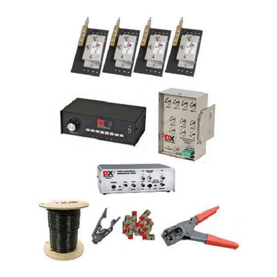
Reduced susceptibility to high angle signals compared to EWE, Flag, Pennant, or K9AY • arrays DXE-RFS-TS2P is a complete Receive Four Square Array Package for Close spacing to transmit antenna which includes: (1) DXE-ARAV2-4P Package of four Active Receive Vertical Antennas w/ Internal •... -
Page 5: System Overview
• Excellent directivity in a small space for better signal-to-noise ratio • Switching of four 90 degree spaced directions • Directivity over a very wide frequency range using DX Engineering’s Active Receive Antennas • Requires less space than a Beverage antenna. Active elements need only a minimal ground system •... -
Page 6: Prerequisite
Prerequisite This manual covers both the DXE-RFS-2P stand-alone unit and the DXE-RFS-TS2P system. This manual will describe the DXE-RFS-TS2P total system package in detail. The DXE-RFS-2P includes the DXE-RFS-2 Receive Four Square Switching Unit and the DXE-CC-8 Control Console. The DXE-RFS-2 includes just the Receive Four Square Switching Unit. The stand-alone DXE-RFS-2 unit must be connected with the appropriate power and switching voltages as defined in the Control &... -
Page 7: Example Of Array Performance
A test array, constructed at DX Engineering using the ARAV Active Elements and a side length of 35 feet, showed excellent performance across a wide frequency range. This side length is optimal for 40m, according to Table 2. - Page 8 In a different test array with 50 ft side lengths, optimum performance occurred between 3 and 4 MHz. Performance on 7 MHz was also excellent. Amplification was used below 2 MHz. The highest usable frequency was 10 MHz. This array also produced usable F/R ratios down to the lower end of the AM broadcast band (600 kHz).
-
Page 9: Site Selection
The DXE-ARAV2-1P Active Elements are bypassed to ground when power is turned off. A programmable sequencer, such as the DXE-TVSU-1, is required for close spacing requirements. The DXE-TVSU-1 is included in the DXE-RFS-TS2P complete Receive Four Square Array Package. -
Page 10: Topographical Considerations
For example, transmitting legal-limit power output (1500 watts) into an ideal four square transmitting antenna produces about 6,000 watts ERP (6 dB gain). Because of the increased radiated power level, nearly 1/2 wavelength minimum spacing between the transmitting and receiving antenna arrays is required. -
Page 11: Ground System
Consult lightning protection and station grounding information in the ARRL handbooks, or by referring to the NEC (National Electric Code). The DX Engineering website also has technical and product information listed under “Lightning Protection and Grounding.” Use lightning surge... -
Page 12: Sizing The Array
Sizing the Array When using active elements, the array side length can be as small as 1/10 wavelength and up to about 1/2 wavelength on the highest frequency to be used. Sizes below 1/10 wavelength result in unusable array sensitivity in the most desired bands. Making side lengths larger than 1/2 wavelength on the highest frequency will split the main lobe and cause pattern and front-to-back degradation. -
Page 13: Four Square Layout
• Performance of the RFS-2 can noticeably decrease if structures radiating even small amounts of noise or signals are within 1-wavelength of the array Figure 2 - Layout of the DXE-RFS-TS2P Four Square System • Measure side-to-side and then corner-to-corner to ensure the element locations are square. -
Page 14: Installation
1" to 2" O.D. pipe. The controller can also be mounted on a sturdy wooden post, but provision for grounding the DXE-RFS-2 unit must be made. The DXE-RFS-2 is designed to be used with the DX Engineering Active Vertical Antennas or it can be used with passive elements. The user manual included with the active elements has instructions for assembly and installation. -
Page 15: Station Feedline, Active Antenna Feedline And Delay Lines
Flooded cable also prevents shield contamination and can be direct-buried. DX Engineering offers an inexpensive preparation tool, part number DXE-CPT-659, that readies the coax for connectors in one operation and comes with an extra cutting cartridge. To ensure weather tight connections, use DXE-SNS6-25 Snap-N-Seal compression style connectors. -
Page 16: Active Antenna Feedlines
If you do not know the VF of the coax you are using, you must directly measure the electrical length of the coax you have or obtain cable with a known VF. The DX Engineering DXE-F6-1000 75 Ω coax has a nominal VF of 0.85. For best performance, the coax for the delay lines should be from the same batch or spool. - Page 17 For Example: An array with 90 foot side spacing, the diagonal length is 127.3 feet. The 0.95 factored physical length for DLY3 electrical length is 120.9 ft. Multiply 120.9 ft. by 0.85 (the VF of DX Engineering 75 Ω coax). The correct physical length for DLY3 is 102.77 feet, or 102 feet 9 inches.
-
Page 18: Control And Power Connections
It is important to use 75 Ω feedline to the operating position from the DXE-RFS-2. Do not use amplifiers, combiners, filters or splitters that are not optimized for 75 Ω systems. Control and Power Connections Prior to installation, you should decide if you want to use the factory configuration or an alternate one. -
Page 19: Default Configuration
Default Configuration The DXE-RFS-2 default configuration uses terminals A & B for the BCD directional control interface and terminal C for operational and active element power. The DXE-CC-8 provides the operational power as well as the 2-bit BCD interface used for directional control. A user-supplied 4- conductor cable is needed to connect the DXE-RFS-2 and the DXE-CC-8. -
Page 20: Dxe-Rfs-Ts2P Default Connection Diagram Using Factory Jumper Settings
DXE-RFS-TS2P Default Connection Diagram Using Factory Jumper Settings Shown with optional PPC-IS-75B/18 DC Pass Through Lightning Protection, optional DXE- RFCC-1 Feedline Current Choke, and optional DXE-RPA-1 HF Preamplifier... -
Page 21: Alternate Configurations
Alternate Configurations The DXE-RFS-2 can be configured to use the coaxial feedline for power or directional control, but not simultaneously. Diagram 2 illustrates one way to use the feedline for directional control with optional hardware. Other configurations are possible. Do not make contradictory jumper settings. Any alternate configuration requires changing the internal jumpers from their default settings. -
Page 22: Diagram 2 - Alternate Configuration
Diagram 2 - Alternate Configuration All Element feedlines, delay lines and station feedlines must be 75 Ohm coaxial cable. Element feedlines can be any length, but must be equal. (Not drawn to scale) RFS-2 Alternate Configuration, Requires Internal Jumper Changes Uses Optional DXE-FVC-1 to control direction using the feedline Uses DXE-CC-8 BCD interface to control the FVC-1 (may also use ground closure) Power to the RFS-2 uses terminal C of the CC-8 (switch positions 5 to 8) -
Page 23: Diagram 3 - Alternate Configuration
Diagram 3 - Alternate Configuration All Element feedlines, delay lines and station feedlines must be 75 Ohm coaxial cable. Element feedlines can be any length, but must be equal. (Not drawn to scale) RFS-2 Alternate Configuration, Requires Internal Jumper Changes Uses optional DXE-FVC-1 to control direction using feedline. -
Page 24: Dxe-Rfs-2 And Active Element Power
DXE-RFS-2 and Active Element Power The DXE-RFS-2 phasing unit uses and distributes the voltage to power the active antenna elements. For all four active elements, a nominal +12-15 Vdc at 200 mA current is required. The default configuration uses Terminal C on the 5-position plug for power. The DXE-CC-8 uses positions 5 through 8 to power and control the DXE-RFS-2. -
Page 25: Internal Jumper Selection
Forward Rear Voltage on Coax or Direction Direction Direction J12 Term C Shift Element 1 Element 3 None 0° Element 2 Element 4 +12 Vdc 90° Element 3 Element 1 -12 Vdc 180° Element 4 Element 2 12 Vac 270° Table 5 - Differential Voltage Control Matrix Internal Jumper Selection To access the DXE-RFS-2 jumper blocks, remove the 6 screws holding the connector plate of the... -
Page 26: Powering Through The Feedline
Powering Through the Feedline To power the DXE-RFS-2 from the feedline, move the JMP1 jumper block from the top and middle pins of the header to the lower and middle pins. When the feedline is used for power, you can use either Terminal C on J12 for directional control using differential voltages, or Terminals A &... -
Page 27: Front-To-Rear (Null) Optimizing
the noise along with the signal. It is always best to use the least gain possible. Depending on conditions, a preamplifier can cause receiver overload; this may require an attenuator or bypassing the preamplifier. The DXE-RPA-1 HF Preamplifier has better dynamic range than most receivers and can be used to compensate for the decrease in array signal output. -
Page 28: Optional Items
If you wish to reduce feedline radiation and improve reception, a Feedline Current Choke is recommended if your SWR is already low. Adding a DX Engineering Feedline Current Choke at the point where the feedline exits the area of the antenna will substantially reduce unwanted feedline radiation or reception without the need for improved station grounding. - Page 29 PPC-IS-75FB/18 - PolyPhaser Lightning Protector, 75 ohm, 18V DC Pass, Type F Connectors The IS-75FB/18 was chosen to compliment the line of receive only antennas from DX Engineering. This is a 75 ohm lightning protector that has type F connectors and passes 18 VDC for control/power at the antenna units.
- Page 30 That's the vinegar smell. The acetic acid causes the corrosion. DX Engineering has located a Neutral Cure RTV made right here in Ohio that is non-corrosive and is safe for sealing those baluns and other electronic gear that are going to be out in the weather.
- Page 31 DXE-900031 - Automatic Wire Stripper/Crimper/Cutter, 24-10 Ga. Our DX Engineering wire stripper uses a spring-loaded design to make quick work of wires ranging from 24 to 10 gauge. Just insert the wire, squeeze the handle, and listen for the click. That’s the sound of another perfect wire stripping job performed in about 2 seconds- a fraction of the time it takes your pocket knife to do the same job.
-
Page 32: Technical Support And Warranty
All products manufactured by DX Engineering are warranted to be free from defects in material and workmanship for a period of one (1) year from date of shipment. DX Engineering’s sole obligation under these warranties shall be to issue credit, repair or replace any item or part thereof which is proved to be other than as warranted; no allowance shall be made for any labor charges of Buyer for replacement of parts, adjustment or repairs, or any other work, unless such charges are authorized in advance by DX Engineering.
Need help?
Do you have a question about the DXE-RFS-TS2P and is the answer not in the manual?
Questions and answers