Table of Contents
Advertisement
Quick Links
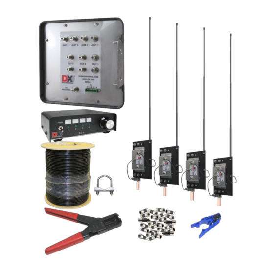
Receive Four Square System
DXE-RFS-SYS-4S
U.S. Patent No. 7,423,588
DXE-RFS-4S-INS Revision 0c
DXE-RFS-SYS-4S Components Shown
© DX Engineering 2020
1200 Southeast Ave. - Tallmadge, OH 44278 USA
Phone: (800) 777-0703 ∙ Tech Support and International: (330) 572-3200
Fax: (330) 572-3279 ∙ E-mail:
DXEngineering@DXEngineering.com
Advertisement
Table of Contents

Related Manuals for DX Engineering DXE-RFS-SYS-4S


Summary of Contents for DX Engineering DXE-RFS-SYS-4S
- Page 1 Receive Four Square System DXE-RFS-SYS-4S U.S. Patent No. 7,423,588 DXE-RFS-4S-INS Revision 0c DXE-RFS-SYS-4S Components Shown © DX Engineering 2020 1200 Southeast Ave. - Tallmadge, OH 44278 USA Phone: (800) 777-0703 ∙ Tech Support and International: (330) 572-3200 Fax: (330) 572-3279 ∙ E-mail:...
-
Page 2: Table Of Contents
Default Configuration Figures Figure 1 - Site Selection Clear Distance Figure 2 - Layout of the DXE-RFS-SYS-4S Four Square System Figure 3 - Active Element L1MF Jumper Locations Figure 4 - Array Diagonal Dimension Figure 5 - Jumper Locations showing Default Settings... -
Page 3: Introduction
Low current DC powered control console allows system operation without AC power mains DXE-RFS-SYS-4S (U.S. Patent No. 7,423,588) is a complete Receive Four Square Array Package which includes: (1) DXE-ARAV4-4P Active Receive Vertical Antennas (4) w/ Internal Antenna Disconnect Relays ... -
Page 4: System Overview
System Overview The DXE-RFS-SYS-4S is an advanced four square receiving system that uses four symmetrically spaced elements to provide switching for a 4-direction receiving antenna system. This unique system uses time delay phasing rather than the single band phase shifting used in traditional four squares. -
Page 5: Additional Parts Required
4-direction selectivity and you still would be limited to one or two bands. The DXE-RFS-SYS-4S system occupies less space, is much easier to install, is less conspicuous and operates over a wider frequency range with similar or better performance. - Page 6 Increasing the array size increases its sensitivity on the lower frequencies, sliding the performance curve toward the low frequencies and potentially eliminating the need for amplification.
-
Page 7: Site Selection
Site Selection Site selection is important. The DXE-RFS-SYS-4S system can be positioned as close as 1/10 wavelength to transmitting antennas. The DXE-ARAV4 Active Elements are bypassed to ground when power is turned off. A programmable sequencer, such as the optional DXE-TVSU-1B will be required with the DXE-RFS-SYS-4S, for close spacing requirements. -
Page 8: Topographical Considerations
60 ft Table 1 - Array Safety Distance Minimums at 1500 watts For any DX Engineering Receive Four Square, using the optional DXE-TVSU-1B Time Variable Sequencer Unit to sequence Active antenna power will ensure that transmitted energy will not cause damage to the receive system. -
Page 9: Ground System
Noise that limits the ability to hear a weak signal on the lower bands is generally a mixture of local ground wave and ionosphere propagated noise sources. Some installations suffer from a dominant noise source located close to the antennas. Noise level differences between urban and rural locations can be more than 30 dB during the daytime on 160 meters. -
Page 10: Sizing The Array
Consult lightning protection and station grounding information in the ARRL handbooks, or by referring to the NEC (National Electric Code). The DX Engineering website also has technical and product information listed under “Lightning Protection and Grounding.” Use lightning surge protectors for the coaxial cable feedline and control lines. -
Page 11: Four Square Layout
If you mount the RFS-3 on a wood post, it should be grounded to a separate ground rod Figure 2 - Layout of the DXE-RFS-SYS-4S Four Square System System Operational Overview The DXE-RFS-SYS-4S system is comprised of the DXE-EC-4 BCD Control Console and the DXE-RFS-3 Control Unit. These units interconnect and work together using factory default settings. -
Page 12: Installation
Seize must be used on all clamps, bolts and stainless steel threaded hardware to prevent galling and to ensure proper tightening. The DXE-RFS-3 is designed to be used with the DX Engineering Active Vertical Antennas. It can also be used with passive elements. The user manual included with the active elements has... -
Page 13: Active Antenna Elements
If the resistance of the shield increases due to contamination, the active elements may not function properly. Any splices in the feedline should be high quality and entirely weather tight. Do not use splices in the delay line cables. The DXE-RFS-SYS-4S system has been designed to use only 75 Ω coaxial cable. -
Page 14: Active Antenna Feedlines
Included with the DXE-RFS-SYS-4S package is the coaxial cable preparation tool, part number DXE-CPT-659, that readies the coaxial cable for connectors in one operation and comes with an extra cutting cartridge. To ensure weather tight connections, use DXE-EX6XL-25 compression style F connectors are also included. DXE- EX6XL-25 contains 25 compression F connectors, enough for the entire array plus some spares. - Page 15 DLY3 electrical length is 120.9 ft. Multiply 120.9 ft. by 0.82 (the VF of DX Engineering 75 Ω quad shield coaxial cable). The correct physical length for DLY3 is 99.14 feet, or 99 feet 1-5/8 inches.
-
Page 16: Control And Power Connections
Control and Power Connections If you have the DXE-RFS-SYS-4S system, with the DXE-EC-4 Control Console, no other equipment is needed for powering the DXE-RFS-SYS-4S, the active elements or controlling the receive direction of the DXE-RFS-SYS-4S. The DXE-RFS-SYS-4S has been factory-set to work with the DXE-EC-4 using four conductor control cable such as COM-CW4. - Page 17 TVSU-1B, the wiring connections are shown in Diagram 1 - Default Configuration. Control lines (usually BCD ) can normally use good quality CAT5e cable (4 twisted pairs of 24 AWG wire) for runs up to 1000 feet. Typical DX Engineering BCD control lines requirements are +12 VDC at 25 milliamps.
-
Page 18: Default Configuration
Default Configuration The DXE-RFS-SYS-4S default configuration, as shown in Diagram 1, uses terminals A & B for the BCD directional control interface and terminal C for operational and active element power. The DXE-EC-4 provides the operational power as well as the 2-bit BCD interface used for directional control. -
Page 19: Diagram 1 - Default Configuration
Diagram 1 - Default Configuration for the DXE-RFS-SYS-4S Shown with optional items. Power connections not shown for clarity. -
Page 20: Optimizing The Array
Optimizing the Array To determine if the antenna system output level is the limiting factor, tune the receiver to the lowest band at the quietest operating time. This is usually when propagation is poor but some signals are heard. Disconnect the antenna and set the receiver to the narrowest selectivity you expect to use. Receiver noise power is directly proportional to receiver bandwidth (going from 2.5 kHz selectivity to 250 Hz selectivity reduces noise by 10 dB). -
Page 21: Normal Receive Four Square Operation
DX operations. Receive Four Square Troubleshooting There are several possible causes for a malfunction of a DX Engineering Receive Four Square System. Testing the system is not difficult and can be completed in an hour or so. Separate circuits for directional switching, Active Vertical Antenna power, and antenna phasing can each be affected by a variety of cabling, connection and or component problems. - Page 22 Start 80% of all Receive Four Square malfunctions are caused by Check Internal A, B or C Jumpers Animals, Chewed, Green Connector may have Punctured, Stretched broken a wire or is tightened Broken/Shorted or Broken. against insulation - not bare wire. Conductors Check all F connector center conductor...
- Page 23 C) Shorted or opened conductors caused by water migration into a control line or a feedline. Over 80% of all Receive Four Square malfunctions have been caused by the above system problems. A thorough inspection and subsequent testing of each control cable, RF cable, and their respective connections, will uncover the cause of most RFS troubles.
- Page 24 4) If the EC-4 has only a couple LEDs lit with the control cable disconnected, then it may have sustained lightning pulse damage and will need to be repaired or replaced. A new DXE-EC-4 is available from DX Engineering. Continue troubleshooting the array control with a good EC-4 or by using a 1A fused power source.
- Page 25 RFS unit may require service or replacement. At this point, the problem in your system should have been identified. If you need additional assistance from DX Engineering, feel free to call or e-mail. Detailed discussions of system function, connections, and troubleshooting is best handled by telephone,...
-
Page 26: Appendix A - Alternate Configurations
Appendix A Alternate Configurations An alternate configuration which uses the feedline coaxial cable for either the operational power or the directional control voltages, but not simultaneously, can be used. This configuration requires internal jumper changes in the DXE-RFS-3, along with additional hardware to couple the proper voltage to the feedline. -
Page 27: Directional Control Using The Feedline
Differential voltages (+/–12 Vdc & 12 Vac) using terminal C. This can be done using a 1 or 2 conductor cable. Economically priced COM-CW-4 is a 4 conductor control wire which may See Table 5 for the control matrix. The optional DXE-FVC-1 can be used to be used. -
Page 28: Diagram 2 - Alternate Configuration
Diagram 2 - Alternate Configuration All Element feedlines, delay lines and station feedlines must be 75 Ω coaxial cable. RFS-3 internal jumper changes are required. Element feedlines can be any length, but must be equal. Power lines not shown for clarity. -
Page 29: Diagram 3 - Alternate Configuration
Diagram 3 - Alternate Configuration Using a manual switch connected to the optional DXE-FVC-1 for directional control All Element feedlines, delay lines and station feedlines must be 75 Ω coaxial cable. Requires RFS-3 internal jumper changes. Element feedlines can be any length, but must be equal. Power lines not shown for clarity. -
Page 30: Dxe-Rfs-3 And Active Element Power
DXE-RFS-3 and Active Element Power The DXE-RFS-3 phasing unit uses and distributes the voltage to power the active antenna elements. For all four active elements, a nominal +12-15 Vdc at 250 mA current is required. The default configuration uses Terminal C on the 5-position plug for power. The DXE-EC-4 is used to power and control the DXE-RFS-3. -
Page 31: Default Jumper Configuration
Default Jumper Configuration Settings Figure 5 shows the default jumper settings for the DXE-RFS-3. For JMP1 & JMP2 the center and top pins of both are shorted. For JMP3 & JMP4, the center and bottom pins of both are shorted. Figure 5 - Jumper Locations showing Default Settings JMP1 Selects Power Voltage Source: Coax or J12 - Shown in default position, voltage from J12 JMP2 Selects Direction Voltage Source: Coax or J12 - Shown in default position, voltage from J12... -
Page 32: Technical Support And Warranty
Warranty All products manufactured by DX Engineering are warranted to be free from defects in material and workmanship for a period of one (1) year from date of shipment. DX Engineering’s sole obligation under these warranties shall be to issue credit, repair or replace any item or part thereof which is proved to be other than as warranted;...
Need help?
Do you have a question about the DXE-RFS-SYS-4S and is the answer not in the manual?
Questions and answers