Advertisement
Hi-Z Antennas
Manual Directional Control Console
for the Receive 8 Circle Array 8PRO
HIZ-MDC-8PRO
HIZ-MDC-8PRO-INS-Revision 0
© DX Engineering 2024
1200 Southeast Ave. - Tallmadge, OH 44278 USA
Phone: (800) 777-0703 Technical Support and International: (330) 572-3200
E-mail: DXEngineering@DXEngineering.com
- 1 -
Advertisement
Table of Contents

Related Manuals for DX Engineering HIZ-MDC-8PRO


Summary of Contents for DX Engineering HIZ-MDC-8PRO
- Page 1 Manual Directional Control Console for the Receive 8 Circle Array 8PRO HIZ-MDC-8PRO HIZ-MDC-8PRO-INS-Revision 0 © DX Engineering 2024 1200 Southeast Ave. - Tallmadge, OH 44278 USA Phone: (800) 777-0703 Technical Support and International: (330) 572-3200 E-mail: DXEngineering@DXEngineering.com - 1 -...
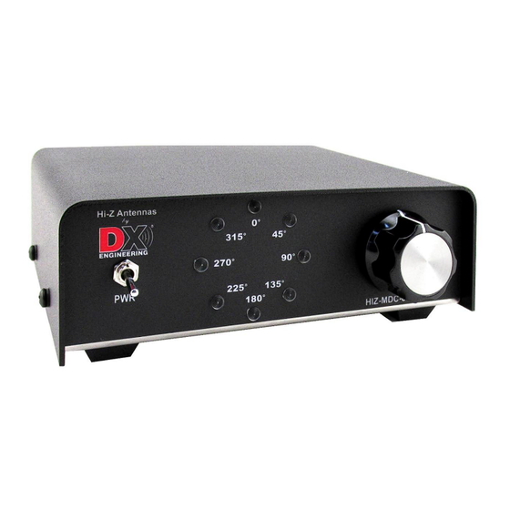
- Page 2 Introduction Hi-Z Antennas HIZ-MDC-8PRO Manual Directional Control Console features a large eight position rotary switch and eight LEDs arranged as array directional azimuth indicators with corresponding compass bearing degree markings on the front panel. This specialized “low-side” BCD grounding switch is specifically designed to operate the Hi-Z Antennas PC-8PRO Phasing Combiner relay unit.
-
Page 3: Front And Rear Panels
Front and Rear Panels On/Off toggle switch Control Wire Feed Through Eight Green LEDs Power Connection 8 Position Rotary Switch Power Cord The DC Input used is +13.8 Vdc. A 2.1 mm power cord is supplied with the unit. The wire with the white stripes is the +13.8 Vdc (Connected to center pin). - Page 4 Interior Control Wire Connections 1. Open the unit by removing the four (two per side) Phillips head screws to remove the cover. 2. Push the end of the cable through the control wire grommet on the rear of the unit. 3.
- Page 5 Control Cable Requirement Table - HIZ-MDC-8PRO 8 Circle Array Voltage Supplied by designated cable lengths and conductor sizes Based on +13.8 VDC input at maximum 550mA system current draw Ω/ft.
-
Page 6: Wiring Example
Wiring Example MDC-8PRO 8PRO Combiner +13.8 Vdc +13.8 Vdc When connecting the cable to the Hi-Z 8PRO Phasing Combiner, ensure your cable is wired the same way at each end to avoid unnecessary troubleshooting. Record which color wire you used to connect to each terminal on both the MDC-8 switch console and the Hi-Z 8PRO Phasing Combiner. -
Page 7: Truth Table
Truth Table The selected position uses the logic as shown in the chart below. Switch Position BCD Out 0° 45° 90° 135° 180° 225° 270° 315° 1 (A) GND GND GND GND 2 (B) GND GND GND GND 3 (C) Notes: - 7 -... -
Page 8: Technical Support
All products manufactured by DX Engineering are warranted to be free from defects in material and workmanship for a period of one (1) year from date of shipment. DX Engineering’s sole obligation under these warranties shall be to issue credit, repair or replace any item or part thereof which is proved to be other than as warranted;...
Need help?
Do you have a question about the HIZ-MDC-8PRO and is the answer not in the manual?
Questions and answers