Table of Contents
Advertisement
Quick Links
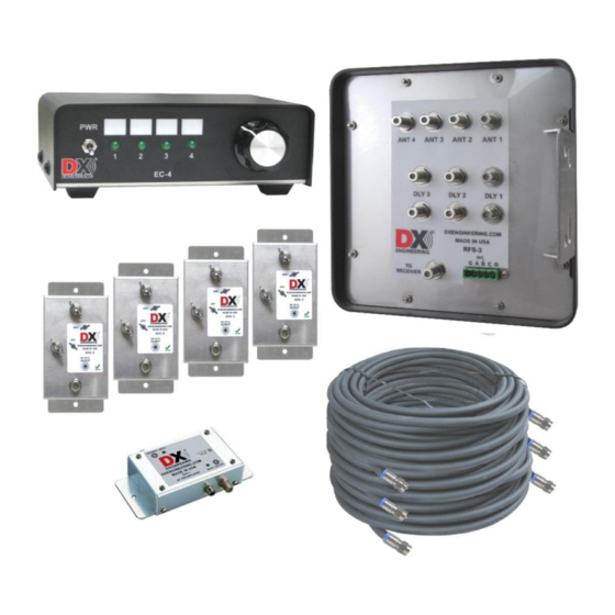
Receive Four Square System
for 160, 80, 40 Meters
DXE-RFS-SYS-3P
U.S. Patent No. 7,423,588
DXE-RFS-SYS-3P-INS Revision 2a
© DX Engineering 2017
1200 Southeast Ave. - Tallmadge, OH 44278 USA
Phone: (800) 777-0703 ∙ Tech Support and International: (330) 572-3200
Fax: (330) 572-3279 ∙ E-mail:
DXEngineering@DXEngineering.com
Advertisement
Table of Contents

Related Manuals for DX Engineering DXE-RFS-SYS-3P


Summary of Contents for DX Engineering DXE-RFS-SYS-3P
- Page 1 Receive Four Square System for 160, 80, 40 Meters DXE-RFS-SYS-3P U.S. Patent No. 7,423,588 DXE-RFS-SYS-3P-INS Revision 2a © DX Engineering 2017 1200 Southeast Ave. - Tallmadge, OH 44278 USA Phone: (800) 777-0703 ∙ Tech Support and International: (330) 572-3200 Fax: (330) 572-3279 ∙ E-mail:...
- Page 2 This patented (US Patent Number 7,423,588) system array configuration embodies unique phase and time shifted combining for stable broadband performance. The DXE-RFS-SYS-3P is a sophisticated receiving system that is designed to be used with four identical vertical symmetrically spaced elements to provide switching for a 4-direction receiving antenna system.
- Page 3 Directivity over a very wide frequency range when using DX Engineering Active Matching unit equipped vertical elements Less physical space and maintenance required than a Beverage antenna and active elements need only a minimal ground system Enhanced relay contact reliability ...
- Page 4 4-direction selectivity and you still would be limited to one or two bands. The DXE-RFS-SYS-3P system occupies far less space, is much easier to install and maintain, is less conspicuous and operates over a wider frequency range with similar or better performance.
- Page 5 The minimum distance to any transmitting antenna from the Four Square perimeter is 1/10-wavelength. Greater than 1/2- wavelength is the distance to prevent coupling to other antennas and the introduction of broadband noise into the receive system. Figure 1 - Site Selection Clear Distance Proximity to Transmitting Antennas The DXE-AVA-2 Active Matching Units with customer supplied vertical elements, or the DXE- ARAV3-1P Receive Antenna Active Vertical with Relay active elements and your transmitting...
-
Page 6: Ground System
Site Selection in Relation to Noise Sources Because the array is directional across its corners, use this example as a guide: If you have a noise source and if your primary listening area is northeast, locate the array northeast of the dominant noise source. -
Page 7: Lightning Protection
Consult lightning protection and station grounding information in the ARRL handbooks, or by referring to the NEC (National Electric Code). The DX Engineering website also has technical and product information listed under “Lightning Protection and Grounding.” Use lightning surge protectors for the coaxial feedline and control lines. -
Page 8: System Operational Overview
If you mount the RFS-3 on a wood post, it should be grounded to a separate ground rod. System Operational Overview The DXE-RFS-SYS-3P system is comprised of the DXE-EC-4 BCD Control Console and the DXE-RFS-3 Control Unit. These units interconnect and work together. - Page 9 Figure 3 - Active Element L1MF Jumper Locations Station Feedline, Active Antenna Feedline and Delay Lines The weakest link in an antenna system, such as the DXE-RFS-SYS-3P, is often the coaxial cable connections. All connections must be high quality and weather tight to prevent contamination and corrosion, which can cause the feedline impedance to change.
- Page 10 The DXE-RFS-SYS-3P includes three sets of custom made delay lines. Made for array side spacing of 70 feet, their electrical length is critical and careful measurements were made when manufacturing these delay lines using high quality 75 Ω...
- Page 11 The DXE-EC4 BCD Control Console uses an internal terminal plug labeled “G 1 2 3”. DXE-EC-4 DXE-RFS-3 Wire connections between the DXE-EC-4 and DXE-RFS-3 The switch position on the DXE-EC-4 controls the directivity of the received signal in the DXE- RFS-SYS-3P.
- Page 12 Control lines (usually BCD ) can normally use good quality CAT5e cable (4 twisted pairs of 24 AWG wire) for runs up to 1000 feet. Typical DX Engineering BCD control lines requirements are +12 VDC at 25 milliamps, well filtered and fused.
- Page 13 DXE-RFS-SYS-3P Connection Diagram Shown with optional DXE-RFCC-1 Feedline Current Choke, Control Cable, Coaxial Cables and Customer supplied vertical antenna elements...
-
Page 14: Internal Jumper Selection
Internal Jumper Selection To access the DXE-RFS-3 jumper blocks, remove the screws holding the cover of the DXE-RFS-3 unit. The jumper blocks should be visible and oriented as shown in Figure 5. Important Note: You cannot use the coaxial cable with the provided items for voltage control functions. -
Page 15: Operation
Optimizing the Array To determine if the antenna system output level is the limiting factor, tune the receiver to the lowest band at the quietest operating time. This is usually when propagation is poor but some signals are heard. Disconnect the antenna and set the receiver to the narrowest selectivity you expect to use. Receiver noise power is directly proportional to receiver bandwidth (going from 2.5 kHz selectivity to 250 Hz selectivity reduces noise by 10 dB). - Page 16 DX operations. Receive Four Square Troubleshooting There are several possible causes for a malfunction of a DX Engineering Receive Four Square System. Testing the system is not difficult and can be completed in an hour or so. Separate circuits for directional switching, Active Vertical Antenna power, and antenna phasing can each be affected by a variety of cabling, connection and or component problems.
- Page 17 Start 80% of all Receive Four Square malfunctions are caused by Check Internal A, B or C Jumpers Animals, Chewed, Green Connector may have Punctured, Stretched broken a wire or is tightened Broken/Shorted or Broken. against insulation - not bare wire. Conductors Check all F connector center conductor...
- Page 18 C) Shorted or opened conductors caused by water migration into a control line or a feedline. Over 80% of all Receive Four Square malfunctions have been caused by the above system problems. A thorough inspection and subsequent testing of each control cable, RF cable, and their respective connections, will uncover the cause of most RFS troubles.
- Page 19 4) If the EC-4 has only a couple LEDs lit with the control cable disconnected, then it may have sustained lightning pulse damage and will need to be repaired or replaced. A new DXE-EC-4 is available from DX Engineering. Continue troubleshooting the array control with a good EC-4 or by using a +12V, 1A, well filtered, fused power source.
- Page 20 RFS unit may require service or replacement. At this point, the problem in your system should have been identified. If you need additional assistance from DX Engineering, feel free to call or write. Detailed discussions of system function, connections, and troubleshooting is best handled by telephone,...
-
Page 21: Optional Items
Optional Items DXE-WP-102 - 102 inch Stainless Steel Whip This 102'' whip antenna is made from the finest 17-7 ph tapered stainless steel which resists bending and kinking. This material is so tough it can be bent 180 degrees and will spring back to its original shape. Dissipation tip to reduce unwanted static buildup. Fits all 3/8 x 24 threaded mounts. - Page 22 SUM-900031 - Automatic Wire Stripper/Crimper/Cutter, 24-10 Ga. Our DX Engineering wire stripper uses a spring-loaded design to make quick work of wires ranging from 24 to 10 gauge. Just insert the wire, squeeze the handle, and listen for the click. That’s the sound of another perfect wire stripping job performed in about 2 seconds- a fraction of the time it takes your pocket knife to do the same job.
- Page 23 If you wish to reduce feedline radiation and improve reception, a Feedline Current Choke is recommended if your SWR is already low. Adding a DX Engineering Feedline Current Choke at the point where the feedline exits the area of the antenna will substantially reduce unwanted feedline radiation or reception without the need for improved station grounding.
-
Page 24: Technical Support
All products manufactured by DX Engineering are warranted to be free from defects in material and workmanship for a period of one (1) year from date of shipment. DX Engineering’s sole obligation under these warranties shall be to issue credit, repair or replace any item or part thereof which is proved to be other than as warranted; no allowance shall be made for any labor charges of Buyer for replacement of parts, adjustment or repairs, or any other work, unless such charges are authorized in advance by DX Engineering.
Need help?
Do you have a question about the DXE-RFS-SYS-3P and is the answer not in the manual?
Questions and answers