Advertisement
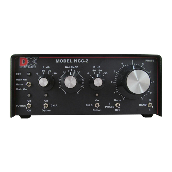
Receive Antenna Phasing Controller
PLEASE - Read this guide completely before applying power or transmitting RF.
You can cause serious damage to the NCC-2 and your receive antenna system by making incorrect
connections to this unit. This type of damage is NOT covered by warranty.
If after reading this guide and the complete NCC-2 manual you still have any questions about the
hook up of the NCC-2 for your system, please call DX Engineering for technical assistance.
Make these connections first then perform the Transmit Safety Test
Make connections to the NCC-2 as follows:
Connect a standard shielded audio style cable between the RADIO PTT Phono
connector and a transceiver keying output that provides a 'ground on transmit'
connection. Some modern transceivers have a rear panel amplifier control jack typically
labeled as "TX", "AMP", "Send" or "TX GND" that pulls low when the transceiver is
keyed. (Check the user manual for your radio). Note: Kenwood transceivers have a 7-pin
DIN labeled "REMOTE". Use the DXE-KWD-RTR cable.
ACC PTT connector on the NCC-2 is a keying pass-through used for keying another
accessory such as an amplifier or sequencer. Do not use this connector for a transceiver keying
line. See warning on second page of this guide.
Connect the NCC-2 RADIO jack to a transceiver antenna jack with a standard coaxial cable.
When using two receiving antennas, connect the first one to the CH A RX ANT IN BNC or F
Connector.
When phasing a receive only antenna with a transmit antenna, connect the included BNC patch
cable between MAIN ANT OUT and CH A RX ANT IN.
Connect the second receiving antenna (or local noise source antenna) to the CH RX B ANT IN
BNC or F Connector.
Connect a well filtered, fused power source of +13.8 to +21 Vdc 2A minimum
to the MAIN PWR jack to the NCC-2 using the supplied 2.1 mm plug. Input DC
line should be fused at 3 amps to protect circuitry. Power will be fed through the
bias tee circuitry to A and B Ports if individually enabled.
See the manual for jumper settings.
Proceed to the Transmit Safety Test on page 2.
NEVER connect the MAIN ANT OUT connector of the NCC-2 to a transceiver RF output!
Quick Start Guide for the NCC-2
described on page 2 of this guide.
--------------------------------
- Page 1 of 2 -
DXE-NCC-2
DXE-NCC-2-Quick Start -INS Rev 0b
Advertisement
Table of Contents

Related Manuals for DX Engineering DXE-NCC-2


Summary of Contents for DX Engineering DXE-NCC-2
- Page 1 If after reading this guide and the complete NCC-2 manual you still have any questions about the hook up of the NCC-2 for your system, please call DX Engineering for technical assistance. Make these connections first then perform the Transmit Safety Test described on page 2 of this guide.
- Page 2 Transceiver ground on transmit on the center conductor AND a transceiver chassis-grounded shield on the keying cable connected to RADIO PTT connector of the NCC-2 are required for proper RTR relay operation. ©DX Engineering 2018 DX Engineering 1200 Southeast Ave. - Tallmadge, OH 44278 USA Phone: (800) 777-0703 ∙...
Need help?
Do you have a question about the DXE-NCC-2 and is the answer not in the manual?
Questions and answers