Table of Contents
Advertisement
Quick Links
Advertisement
Table of Contents

Related Manuals for DX Engineering DXE-RFS-SYS-2P


Summary of Contents for DX Engineering DXE-RFS-SYS-2P
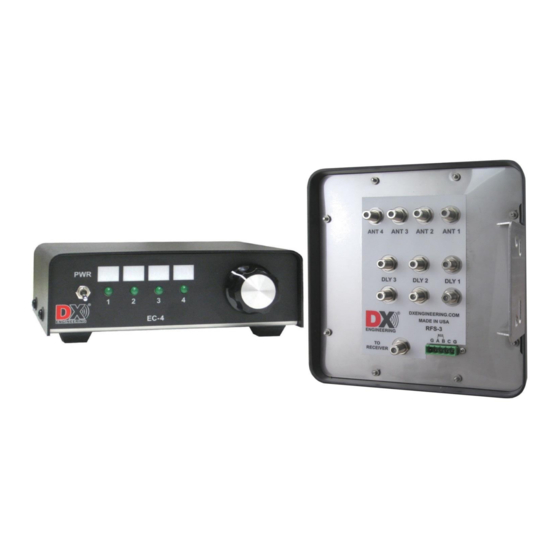
- Page 1 Receive Four Square System DXE-RFS-SYS-2P U.S. Patent No. 7,423,588 DXE-RFS-SYS-2P-INS Revision 2a © DX Engineering 2017 1200 Southeast Ave. - Tallmadge, OH 44278 USA Phone: (800) 777-0703 ∙ Tech Support and International: (330) 572-3200 Fax: (330) 572-3279 ∙ E-mail: DXEngineering@DXEngineering.com...
- Page 2 This patented (US Patent Number 7,423,588) system array configuration embodies unique phase and time shifted combining for stable broadband performance. The DXE-RFS-SYS-2P is a sophisticated receiving system that is designed to be used with four identical vertical symmetrically spaced elements to provide switching for a 4-direction receiving antenna system.
- Page 3 Feedline connections must have good integrity and be weather resistant. We recommend Snap-N-Seal type F connectors. The complete DXE-RFS-SYS-2P system, including feedline connections, requires 16 type F connectors. DXE-SNS6-25 contains 25 Snap-N-Seal connectors, enough for the entire array plus nine spare connectors.
-
Page 4: Site Selection
4-direction selectivity and you still would be limited to one or two bands. The DXE-RFS-SYS-2P system occupies less space, is much easier to install, is less conspicuous and operates over a wider frequency range with similar or better performance. - Page 5 With 1500 watts output and a unity gain (0 dB) antenna, the closest active element can be 1/10 wavelength from the transmitting antenna at the lowest transmitting frequency. Doubling the protection distance quadruples safe power levels. See Table 1. Band Unity (0 dB) Gain 3 dB Gain (2x) 6 dB Gain (4x)
-
Page 6: Ground System
Noise that limits the ability to hear a weak signal on the lower bands is generally a mixture of local ground wave and ionosphere propagated noise sources. Some installations suffer from a dominant noise source located close to the antennas. Noise level differences between urban and rural locations can be more than 30 dB during the daytime on 160 meters. -
Page 7: Lightning Protection
Consult lightning protection and station grounding information in the ARRL handbooks, or by referring to the NEC (National Electric Code). The DX Engineering website also has technical and product information listed under “Lightning Protection and Grounding.” Use lightning surge protectors for the coax feedline and control lines. -
Page 8: System Operational Overview
DXE-RFS-3 unit must be made. The DXE-RFS-3 is designed to be used with the DX Engineering Active Vertical Antennas or, it can be used with passive elements. The active elements should be installed as close to the ground as possible but above any standing water line. - Page 9 Manual for more information about additional peak response jumper settings. Station Feedline, Active Antenna Feedline and Delay Lines The weakest link in an antenna system, such as the DXE-RFS-SYS-2P, is often the coax cable connections. All connections must be high quality and weather tight to prevent contamination and corrosion, which can cause the feedline impedance to change.
- Page 10 If you do not know the VF of the coax you are using, you must directly measure the electrical length of the coax you have or obtain cable with a known VF. The DX Engineering DXE-F6-1000 75 Ω coax has a nominal VF of 0.85. For best performance, the coax for the delay lines should be from the same batch or spool.
- Page 11 Element 1. Element 3 is the rear or null direction. Control and Power Connections The DXE-RFS-SYS-2P system, with the DXE-EC-4 BCD Control Console, no other equipment is needed for powering the DXE-RFS-3, the active elements or controlling the receive direction.
- Page 12 Control lines (usually BCD ) can normally use good quality CAT5e cable (4 twisted pairs of 24 AWG wire) for runs up to 1000 feet. Typical DX Engineering BCD control lines requirements are +12 VDC at 25 milliamps. Depending on the number of control lines needed (usually 3 or 4) you can double up the twisted pairs of CAT5e cable, or use control wire that is at least 22 AWG, allowing runs up to 1500 feet.
- Page 13 Approximate Active Antenna Power Line Lengths (4 active antennas on at any one time). Minimum Copper Length Wire Gage (AWG) 300 Feet 500 feet 1,200 feet 2,000 feet DXE-RFS-SYS-2P Connection Diagram Shown with optional DXE-RFCC-1 Feedline Current Choke, DXE-RPA-1 HF Preamplifier and DXE-ARAV3-4P Active Vertical Receive Antenna units.
-
Page 14: Internal Jumper Selection
Internal Jumper Selection To access the DXE-RFS-3 jumper blocks, remove the screws holding the cover of the DXE-RFS-3 unit. The jumper blocks should be visible and oriented as shown in Figure 5. Important Note: You cannot use coax for multiple functions. If you are going to use the coax for directional control, then you cannot use the coax for powering active elements. -
Page 15: Operation
If the array is used on 160m or below, the Active Antenna internal jumper should be set as shown in the Installation Section of this manual. If the array still lacks sensitivity on the lower bands, then a preamplifier with high dynamic range should be used to compensate for the low signal level. Using a preamplifier when sufficient signal is already present may result in amplification of the noise along with the signal. - Page 16 There are several possible causes for a malfunction of a DX Engineering Receive Four Square System. Testing the system is not difficult and can be completed in an hour or so. Separate circuits for directional switching, Active Vertical Antenna power, and antenna phasing can each be affected by a variety of cabling, connection and or component problems.
- Page 17 Start 80% of all Receive Four Square malfunctions are caused by Check Internal A, B or C Jumpers Animals, Chewed, Green Connector may have Punctured, Stretched broken a wire or is tightened Broken/Shorted or Broken. against insulation - not bare wire. Conductors Check all F connector center conductor...
- Page 18 C) Shorted or opened conductors caused by water migration into a control line or a feedline. Over 80% of all Receive Four Square (RFS) malfunctions have been caused by the above system problems. A thorough inspection and subsequent testing of each control cable, RF cable, and their respective connections, will uncover the cause of most RFS troubles.
- Page 19 4) If the EC-4 has only a couple LEDs lit with the control cable disconnected, then it may have sustained lightning pulse damage and will need to be repaired or replaced. A new DXE-EC-4 is available from DX Engineering. Continue troubleshooting the array control with a good EC-4 or by using a well filtered 1A fused power source.
- Page 20 RFS unit may require service or replacement. At this point, the problem in your system should have been identified. If you need additional assistance from DX Engineering, feel free to call or write. Detailed discussions of system function, connections, and troubleshooting is best handled by telephone,...
-
Page 21: Optional Items
Optional Items DXE-WP-102 - 102 inch Stainless Steel Whip This 102'' whip antenna is made from the finest 17-7 ph tapered stainless steel which resists bending and kinking. This material is so tough it can be bent 180 degrees and will spring back to its original shape. Dissipation tip to reduce unwanted static buildup. Fits all 3/8 x 24 threaded mounts. - Page 22 DX Engineering’s Active Receive Antenna system offers excellent receiving performance from 100 kHz to 30 MHz using a whip antenna element 102 in. long. DX Engineering’s unique design makes it vastly superior to traditional active antennas in both strong signal handling and feedline decoupling.
- Page 23 If you wish to reduce feedline radiation and improve reception, a Feedline Current Choke is recommended if your SWR is already low. Adding a DX Engineering Feedline Current Choke at the point where the feedline exits the area of the antenna will substantially reduce unwanted feedline radiation or reception without the need for improved station grounding.
-
Page 24: Technical Support
All products manufactured by DX Engineering are warranted to be free from defects in material and workmanship for a period of one (1) year from date of shipment. DX Engineering’s sole obligation under these warranties shall be to issue credit, repair or replace any item or part thereof which is proved to be other than as warranted; no allowance shall be made for any labor charges of Buyer for replacement of parts, adjustment or repairs, or any other work, unless such charges are authorized in advance by DX Engineering.
Need help?
Do you have a question about the DXE-RFS-SYS-2P and is the answer not in the manual?
Questions and answers