Table of Contents
Advertisement
Advertisement
Table of Contents

Related Manuals for SKF TKSA 20


Summary of Contents for SKF TKSA 20
- Page 1 SKF Shaft Alignment Tool TKSA 20 Instructions for use...
-
Page 3: Table Of Contents
Alignment report ....................22 Advanced use ....................24 5.1 Limited rotation ......................24 5.2 Trouble shooting ......................24 5.2.1 The system does not switch on ...............24 5.2.2 No laser lines .....................24 5.2.3 No measurement values ..................24 5.2.4 Fluctuating measurement values ..............24 5.2.5 Incorrect measuring results................25 5.2.6 Measurement results cannot be repeated ............25 Maintenance....................25 6.1 Handle with care ......................25 6.2 Cleanliness ........................25 6.3 Batteries of the display unit ..................25 6.4 Replacement of measuring units or display unit ............25 6.5 Spare parts and accessories ..................26 SKF TKSA 20... -
Page 4: Ec Declaration Of Conformity
EC Declaration of conformity We, SKF Maintenance Products, Kelvinbaan 16, 3439 MT Nieuwegein, declare that SKF Shaft Alignment Tool TKSA 20 has been designed and manufactured in accordance with EMC DIRECTIVE 2004/108/EC as outlined in the harmonized norm for Emission: EN 61000-6-3:2007 Immunity: EN 61000-6-2:2005, EN 61000-4-2, -3 Directive RoHS, 2002/95/EC The laser is classified in accordance with the EN 60825-1:2007. The laser complies with 21 CFR 1040.10 and 1040.11 except for deviations pursuant to Laser Notice No. 50, dated June 24, 2007. The Netherlands, March 2010 Sébastien David Manager Product Development and Quality SKF TKSA 20... -
Page 5: Safety Recommendations
Safety recommendations • Always turn off the power of the drive machine before you start working. • Do not expose the equipment to rough handling or heavy impacts. • Always read and follow the operating instructions. • The tool uses two laser diodes with an output power below 1 mW. Still, never stare directly into the laser transmitter. • Calibrate the equipment regularly. • Never aim the laser line into someone’s eyes. • Opening the housing of the measuring unit may result in hazardous light exposure and voids warranty. • The equipment should not be used in areas where there is a risk for explosion. • Do not expose the equipment to high humidity or direct contact with water. • All repair work should be taken care of by an SKF repair shop. SKF TKSA 20... -
Page 6: Introduction
1.1 Principle of operation The TKSA 20 system uses two measuring units both provided with a laser diode and a positioning detector. As the shafts are rotated through 180° any parallel misalignment or angular misalignment causes the two laser lines to deflect from their initial relative position. The measurements from the two positioning detectors automatically enter the logic circuitry inside the display unit, which calculates the misalignment of the shafts and advises on corrective alignments of the machine feet. Fig. 1. Parallel misalignment Fig. 2. Angular misalignment After a straightforward measuring procedure, the tool immediately displays the misalignment of the shafts and the necessary corrective adjustments of the feet of the machine. Since the calculations are done in real time the progress of the alignment can be followed live. 1.2 Machine configuration During the alignment procedure we will refer to the part of the machinery which will be adjusted as the “Movable machine”. The other part we will refer to as the “Stationary machine”. Fig. 3. Stationary and Movable machine SKF TKSA 20... -
Page 7: Measuring Positions
1.3 Measuring positions To define the various measuring positions during the alignment procedure we use the analogy of a clock as viewed from behind the Movable machine. The position with the measuring units in an upright position is defined as 12 o’clock while 90° left or right is defined as 9 and 3 o’clock. Fig. 4. The analogy of a clock Stationary Movable Movable machine SKF TKSA 20... -
Page 8: Shaft Alignment Tool
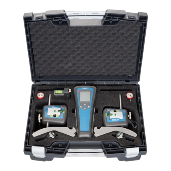
2. Shaft alignment tool The following components are included with the TKSA 20 tools: • Display unit • 2 measuring units with spirit levels • 2 mechanical shaft fixtures • 2 locking chains • Measuring tape • Quick start guide • Certificate of calibration • CD ROM, including: - Instructions for use - Quick start guide - Demonstration video - Shaft alignment report • Batteries • Carrying case Fig. 5. Tool components SKF TKSA 20... - Page 9 1 Connector for measuring unit on Stationary machine 2 Connector for measuring unit on Movable machine 3 LCD Display /mils 4 ON/OFF button 5 Increase (+) button 6 Next button 7 Decrease (-) button 8 Previous button 9 Machine dimensions (A,B and C) / Measured values (S and M) 10 Rear feet values 11 Front feet values 12 Indication of parallel coupling value direction 13 Indication of angular coupling value direction 14 Position (9/12/3 o’clock) of measuring units 15 Low battery 16 Imperial or metric units Fig. 6. Display unit SKF TKSA 20...
- Page 10 Fig. 7. Mechanical fixture with measuring unit Laser emission Release / tightening knob Laser warning signal Connection rod Laser detector Chain fixation screw Vertical fine adjustment Locking chain Spirit level Mechanical fixture SKF TKSA 20...
-
Page 11: Technical Data
Display unit Housing material ABS plastic Display type LCD 35 x 48 mm (1.4 x 1.9 in) Battery type 2 x 1.5V LR14 Alkaline Operating time 20 hours continuous operating Auto power off after 1 hour if no keys are pressed Displayed resolution 0.01 mm (0.1 mil with “inch” setting) Dimensions 215 x 83 x 38 mm (8.4 x 3.2 x 1.4 in) Weight 300 g (10.5 oz Complete system Shaft diameter range 30 - 150 mm (1.2 - 5.9 in) Optional chain 150 - 500 mm (5.9 - 20 in) Accuracy of system <2% +/-0.01mm Temperature range 0-40 °C (32 - 104 °F) Operating humidity < 90% Carrying case dimensions 390 x 310 x 147 (15.3 x 12.2 x 5.7 in) Total weight (incl. case) 3.6 kg (7.9 lb) Calibration certificate valid for two years Warranty 12 months SKF TKSA 20... -
Page 12: Instructions For Use
Metric or imperial sizes The tool is delivered with a pre-selection for measurements in millimeter. In case you want to change into inches, press the minus sign simultaneously to switching the tool on. To revert back to millimeter press the plus sign when switching on. The last setting will always be remembered. 3.2 Feet on the ground If there is any doubt whether the machine is resting equally on all feet please check for so called “soft foot”. The procedure for this operation is described in chapter 3.10. 3.3 Attachment of measuring units a) Use the fixtures to attach the measuring units to the shafts. Make sure that the M-marked unit is attached to the Movable machine and the S-marked unit to the Stationary machine. For diameters larger than 150 mm, an accessory extension chain (TMEA C2) is required. Fig. 8. Attachment of mechanical fixture with chain If it is not possible to attach the fixtures directly to the shafts (e.g. in case of space problems) the fixtures can be attached to the coupling. Note! It is highly recommended to position the measuring units at equal distance from the middle of the coupling. SKF TKSA 20... -
Page 13: Switch On
Connect the measuring units to the display unit. Make sure that the marking on the cables corresponds to the marking of the ports in the display unit (fig. 9). Fig. 9. Connection of the measuring units 3.4 Switch on Switch on the display unit by pressing the ON/OFF button. You will now be prompted to enter the machine dimensions as per chapter 3.6. If no button is pressed within 60 minutes, the unit will turn off automatically. 3.5 Aiming the laser lines a) Put the two measuring units in the 12 o’clock position with the help of the spirit levels (fig. 10). Fig. 10. The 12 o’clock position SKF TKSA 20... - Page 14 Aim the laser lines so that they hit in the centre of the target of the opposite measuring unit (fig. 11). Fig. 11. Hit the target A Laser line c) For coarse adjustment release the measuring unit by unlocking the knob on the side of the unit (fig. 12). This allows the measuring unit to slide up and down the rod at the same time as it can swivel freely. For the fine adjustment in height use the adjustment wheels on the measuring units. Fig. 12. Adjustment mechnism Vertical positioning of measuring unit Horizontal rotation of measuring unit Vertical fine adjustment of laser SKF TKSA 20...
- Page 15 If the horizontal alignment is very poor the laser lines might travel outside the detector areas. If this happens a rough alignment must be done. Do this by aiming the laser lines at the positioning detectors in the 9 o’clock position. Turn the measuring units to the 3 o’clock position when the lines will hit outside the detector areas. Adjust the lines to the position half-way between the detector centre and the actual position by means of the adjustment mechanism as per fig. 13. Align the Movable machine until the lines hit the centre of the positioning detector. Fig. 13. Rough alignment The beam moves outside the detector area Adjust the beam to half the travel Direct the machine to hit the centre SKF TKSA 20...
-
Page 16: Machine Dimensions
3.6 Machine dimensions The configuration of the machinery is defined by three dimensions. A: The distance between the two measuring units, as measured between the fixture centre marks. B: The distance between the M-marked measuring unit and the front pair of feet of the Movable machine. C: The distance between the front feet and the rear feet of the Movable machine. Fig. 14. Machine dimensions a) Measure the A, B and C distances. The default values for these three distances are: A = 200 mm (8 in) B = 200 mm (8 in) C = 400 mm (15 in) b) Adjust each value by using the + and - buttons. c) Confirm the setting of each value by pressing the “next” button. Note! If you need to go back and change values already entered use the “previous” button. Fig. 15. Distances A, B and C SKF TKSA 20... -
Page 17: Measuring Sequence
Display guides you to the 9 o’clock position a) Adjust the measuring units to the 9 o’clock position with the aid of the spirit levels (fig. 17). b) Confirm the measurement by pressing Fig. 17. Adjust to the 9 o’clock position c) Follow the circle symbol on the display and rotate the measuring units to the 3 o’clock position (fig. 18). d) Confirm the measurement by pressing Note! By pressing the “previous” button , you will reverse the process in order to repeat any of the measurement steps or to adjust any of the machine dimensions Fig. 18. Rotate to the 3 o’clock position SKF TKSA 20... -
Page 18: Alignment Results
Coupling values The coupling value on top of the display shows the angle between the centre lines of the two shafts in the measurement plane (measured in mm/100 mm or 0.001”/1”). The value below on the display shows the parallel off-set of the two centre lines in the measurement plane. These two values are the coupling values in the measurement plane. Feet values The values F1 and F2 on the display indicate the relative positions of the Movable machine in the measurement plane. Fig. 19. Measured misalignment The F1 value indicates the relative position of the front pair of feet of the Movable machine. The F2 value indicates the relative position of the rear pair of feet of the Movable machine. 3.8.2 Vertical alignment Adjust the measuring units to the 12 o’clock position (fig. 20) with the aid of the spirit levels. Observe the coupling and feet values live adjustment. Fig. 20. The 12 o’clock position SKF TKSA 20... - Page 19 0.05 4000 - 6000 0.05 0.03 a) If the measured coupling values are within the tolerances, the Movable machine does not have to be adjusted. Correct the horizontal misalignment. Continue to chapter 3.8.3 Horizontal alignment. b) If the measured coupling values are higher than the acceptable tolerances check the recommended corrections of the feet. The F1 and F2 values on the display indicate the relative positions of the Movable machine when viewed from the side (fig. 21). Fig. 21. Display vertical alignment A positive value means that the feet are too high and need to be lowered while a negative value means the opposite (fig. 22). Loosen the feet of the movable machine. Use the shims included with the tool to adjust the height of the machine. Observe the coupling and feet values live adjustment and compare them with the values in table 1. Fig. 22. Vertical alignment After having carried out the vertical alignment proceed to the horizontal alignment (chapter 3.8.3). SKF TKSA 20...
-
Page 20: Horizontal Alignment
3.8.3 Horizontal alignment Move the measuring units to the 3 o’clock position (fig. 23). Observe the coupling and feet values live adjustment. Fig. 23. The 3 o’clock position Machine misalignment should be within the manufacturer’s specified tolerances. In case such tolerances are missing, table 1 can again be used as a general recommendation. a) If the measured coupling values are within the tolerances, no sideways adjustment is necessary. b) If the measured coupling values are higher than the acceptable tolerances check the recommended correction on the feet. Fig. 24. Horizontal alignment SKF TKSA 20... -
Page 21: Verify Alignment
The F1 and F2 values indicated on the display give the relative positions of the Movable machine when viewed from above (fig. 25). The F1 value for the front pair of feet, the F2 value is for the rear pair of feet. The alignment values indicate the necessary corrective sideways movement of the Movable machine (when viewed from behind the Movable machine). A negative value means that the feet have to be moved to the right. A positive value means that the feet have to be moved to the left (fig. 26). Observe the coupling and feet values live adjustment while moving the movable machine sideways and compare them with the values in table 1. The alignment is complete. Tighten the feet of the Fig. 25. Display horizontal alignment movable machine. Fig. 26. Horizontal alignment 3.9 Verify alignment To verify the alignment of the machinery, it is recommended to execute the measuring procedure once again. To do so, go back by using the previous button until you reach the first measuring step (9 o’clock position) and continue as per chapter 3.7. SKF TKSA 20... -
Page 22: Soft Foot
Fig. 27. Soft foot A Soft foot 3. Press + and - simultaniously to reach the soft foot /mils mode. The text “soft foot” should now be visible on the screen as shown on the figure 28. 4. Position the measuring units in the 12 o’clock position. 5. Press Next to zero the display values Fig. 28. Soft foot display 6. Loosen one of the bolts and monitor the change of the displayed values. Monitor the changes of the F1 value for a front foot, and of the F2 value for a rear foot. • If the deviations are less than 0.05 mm (2 mils), the foot has a good support. Tighten the bolt and go to the next foot. • If any of the deviations is larger than 0.05 mm (2 mils), the foot or its diagonally opposed foot is a soft foot. Tighten the bolt and check the diagonally opposed foot. • If the deviation is larger than the previously tightened foot, then this is the soft foot. • If not, tighten the bolt and go back to the previous diagonally opposed foot. It is normally worthwhile to try to improve the support of the soft foot by adding shims. Add the amount of shims corresponding to the larger deviation measured. SKF TKSA 20... -
Page 23: Alignment Report
Maximum acceptable off-set of centre lines (see table 1, Ch. 3.8.2) i) Selection of metric or imperial dimensions j) Machine configuration; distances A, B and C k) Soft foot correction done l) Vertical alignment: resulting angular error m) Vertical alignment: resulting parallel offset n) Horizontal alignment: resulting angular error o) Horizontal alignment: resulting parallel offset p) Vertical alignment: resulting height position of the front feet q) Vertical alignment: resulting height position of the rear feet r) Height of shims to be added or removed under front feet (excluding soft foot correction) s) Height of shims to be added or removed under rear feet (excluding soft foot correction) t) Horizontal alignment: resulting sideways position of the front feet u) Horizontal alignment: resulting sideways position of rear feet v) Remaining vertical angle w) Remaining vertical off-set x) Remaining horizontal angle y) Remaining horizontal off-set z) Space for own notes SKF TKSA 20... - Page 24 SKF TKSA 20...
-
Page 25: Advanced Use
Replace the batteries. Use principally Alkaline batteries for a better life span. 5.2.2 No laser lines a) Make sure that the display unit is switched ON. b) Check the cables and connectors. Assure that all cables are properly connected. c) Check to see if the measuring units’ warning LEDs flash. d) Replace the batteries. 5.2.3 No measurement values a) Check the cables and connectors. b) Assure that the laser lines hit the positioning detectors. c) Assure uninterrupted travel of the laser lines. 5.2.4 Fluctuating measurement values a) Assure tight attachment of fixtures and measuring units. b) Assure that the laser lines hit the detectors. c) Assure that air turbulence does not influence the measurement. d) Assure that direct bright light or obstructed laser lines do not influence the measurement results. SKF TKSA 20... -
Page 26: Incorrect Measuring Results
Check if there are any loose mechanical parts, play in bearing or movements in the machinery. c) Check the status of foundation, base plate, bolts and existing shims 6. Maintenance 6.1 Handle with care The measuring units are equipped with sensitive electronic and optical parts. Handle them with care. 6.2 Cleanliness For best function the system should be kept clean. The optics near the laser and detector should be free of finger prints. If necessary clean with cotton cloth. 6.3 Batteries of the display unit The display unit is powered by two LR14 (C) batteries. Most LR14 (C) batteries can be used, but Alkaline batteries have the longest life. If not using the system for a long period, remove the batteries from the display unit. Flat batteries will be indicated by the battery signal on the display. 6.4 Replacement of measuring units or display unit Both measuring units are calibrated in pairs and hence they must be replaced as a pair. SKF TKSA 20... -
Page 27: Spare Parts And Accessories
6.5 Spare parts and accessories Designation Description TKSA 20-DU Display unit (TKSA 20 system) TKSA-MU Set of measuring units Movable and Stationary (TKSA and TMEA 2 system) TMEA C1 Locking chains, set (500 mm) + tightening tool TMEA C2 Extension chains set (1020 mm) TMEA F2 1 chain fixture, complete TMEA F7 Set with 3 pairs of connection rods (short: 150 mm, standard: 220 mm, long: 320 mm) TMAS 340 Complete kit of 340 pre-cut machinery shims TMAS 360 Complete kit of 360 pre-cut machinery shims TMAS 510 Complete kit of 510 pre-cut machinery shims TMAS 720 Complete kit of 720 pre-cut machinery shims SKF TKSA 20... - Page 28 SKF Maintenance Products ® SKF is a registered trademark of the SKF Group. © SKF 2010/03 www.mapro.skf.com www.skf.com/mount...
Need help?
Do you have a question about the TKSA 20 and is the answer not in the manual?
Questions and answers