Samsung SCX-4216F Service Manual
Digital
Hide thumbs
Also See for SCX-4216F:
- User manual (225 pages) ,
- Service manual (135 pages) ,
- Getting started (72 pages)

Related Manuals for Samsung SCX-4216F


Summary of Contents for Samsung SCX-4216F
-
Page 1: Table Of Contents
DIGITAL LASER MFP SCX-4216F SCX-4116 SCX-4016 SERVICE Manual DIGITAL LASER MFP CONTENTS 1. Precautions 2. Reference Information 3. Specifications 4. Summary of product 5. Disassembly and Reassembly 6. Alignment and Adjustments 7. Troubleshooting 8. Exploded Views and Parts List 9. Block Diagram... - Page 2 This service manual is also provided on the web, © Samsung Electronics Co.,Ltd. March 2003 the ITSELF system f Samsung Electronics Co., Ltd. Printed in Korea. http://itself.sec.samsung.co.kr VERSION NO. : 1.00 CODE : JC-0095A...
- Page 3 Copyright(c) 2003.03...
-
Page 4: Precautions
VARNING - OSYNLIG LASERSTR LNING N R DENNA DEL R PPNAD OCH SP RREN R URKOPPLAD. BETRAKTA EJ STR LEN. STR LEN R FARLIG. VARO! - AVATTAESSA JA SUOJALUKITUS OHITETTAESSA OLET ALTTIINA N KYM TT M LLE LASER- S TEILYLLE L KATSO S TEESEEN. Service Manual Samsung Electronics... -
Page 5: Caution For Safety
A fire can occur if unit is used under these conditions. (13) Do not insert steel or metal pieces inside/outside of the machine. Do not put steel or metal piece into the ventila-tor. An electric shock can occur. Service Manual Samsung Electronics... - Page 6 (4) Do use formal parts and same standardized goods when replacing parts. Must check the product name, part code, rated voltage, rated current, operating temperature, etc. (5) Do not use excessive force when looening or tightening of plastic parts. (6) Be careful not to drop small parts or objects in the machine. Service Manual Samsung Electronics...
-
Page 7: Esd Precautions
9. Minimize bodily motions when handling unpackaged replacement ESDs. Normal motions, such as the brushing together of clothing fabric and lifting one’s foot from a carpeted floor, can generate static electric- ity sufficient to damage an ESD. Service Manual Samsung Electronics... -
Page 8: Reference Information
Standard : For general home use, for medical service. Electronic Scale Standard: Equipment to check the weight of consumables supplied by Samsung Electronics. (The gram unit can be mea- sured.) Cleaning Equipments a IPA (Isopropyl Alcohol)dry cloth or a soft stuff neutral detergent. -
Page 9: Acronyms And Abbreviations
Enhanced Parallel Port Read Only Memory firmware Second Cassette Feeder graphics device interface SMPS Switching Mode Power Supply ground SPGP Samsung Printer Graphic Processor Host Based Printing Samsung Printer Language Hard Disk Drive Spool Simultaneous Peripheral Operation Online high voltage Switch HVPS... - Page 10 The sample pattern shown in below is the standard pattern used in a factory. The contents of the life span and the printing speed are measured with the pattern shown in below. (The picture in the manual is 70% size of the actual A4 size.) 2.3.1 A4 5% Pattern Service Manual Samsung Electronics...
- Page 11 R E F E R E N C E I N F O R M AT I O N 2.3.2 A4 2% Pattern Service Manual Samsung Electronics...
- Page 12 R E F E R E N C E I N F O R M AT I O N 2.3.3 A4 IDC 5% Patten Service Manual Samsung Electronics...
- Page 13 R E F E R E N C E I N F O R M AT I O N Service Manual Samsung Electronics...
-
Page 14: Specifications
3.1 General Specifications Items Descriptions Remarks Major Features SCX-4016 Copier, Print, Scan Without ADF SCX-4116 Copier, Print, Scan With ADF SCX-4216F Copier, Print, Scan, Fax With ADF Size (W*D*H) SCX-4016 474x436x353mm SCX-4216F/4116 474x436x417mm Weight SCX-4016 11.7 Kg (25.8 lbs) With Toner Cartridge SCX-4216F/4116 13 Kg (28.8 lbs) - Page 15 256 level Scan Method Color CCD ITU-T #1 Chart *Scan Speed Up to 25 Sec Text/Mixed Mode : (seconds/scan) (SCX-4216F/4116) B/W Letter & 300dpi. (USB) Up to 72 Sec Photo Mode : Gray Letter & 300dpi. (USB) Platen Up to 23 Sec...
-
Page 16: Copy Specification
25% to 400 % Multi Copy 1~99 Preset Contrast Control 3 level(by LED) Copy Mode TEXT/MIXED/PHOTO Collation Copy Yes(300dpi only) SCX-4216F/4116 Auto return to default mode Yes(after 1 minute) N-up copy 2-up, 4-up SCX-4216F/4116 AutoFit Copy Platen Only Clone Platen Only... - Page 17 Specifications 3.5 Telephone Specification (SCX-4216F Only) Items Descriptions Remarks Handset On hook Dial Search Yes (Phone Book) 1-Touch Dial 10EA (3*4 Numeric Key) Auto dial 100 locations (Using 3*4 buttons) TAD I/F Tone/Pulse Selectable in Tech Mode Pause Auto Redial...
- Page 18 Specifications 3.6 Fax Specification (SCX-4216F Only) Items Descriptions Remarks Compatibility ITU-T G3 Communication System PSTN/PABX Modem Speed 33.6 Kbps TX Speed Approx. 3 sec Compression MH/MR/MMR/JPEG Resolution Up to 203 x 98 DPI effective output Fine Up to 203 x 196 DPI effective output S.Fine...
-
Page 19: Paper Handling
Remarks Compatibility Win 3.x Win 95 Win 98&WinME Win NT 4.0 Win 2000 Win XP WHQL for Printer Only Mac Printer Only Linux Driver Printer TWAIN PC-FAX PC Fax is only avail- able through PC Modem Service Manual Samsung Electronics... - Page 20 Remarks Type Single Cartridge How to install Front door open and front loading Toner Life Up to 1,000 Sheets Initial toner life could Up to 3,000 Sheets be different accroding to country Level Sensor Toner Count Service Manual Samsung Electronics...
- Page 21 Specifications Service Manual Samsung Electronics...
-
Page 22: Summary Of Product
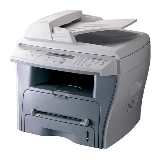
4.1 Printer Components 4.1.1 Front View Document Document Cover Guides Automatic Document Document Feeder Input Tray (for SCX-4116/4216F) Document Glass Document Output Tray Control Panel Front Cover Paper Output Extension Paper Tray Paper Level Indicator Bypass Tray Service Manual Samsung Electronics... -
Page 23: Rear View
SUMMARY OF PRODUCT 4.1.2 Rear View Rear Cover Rear Output Slot (Face up) Parallel Power Switch Telephone Line Connector Connector AC Power Cord (for SCX - 4216F) Connector Connector Service Manual Samsung Electronics... -
Page 24: Control Panel
SUMMARY OF PRODUCT 4.1.3 Control Panel < SCX-4216F > Adjusts the brightness of the documents for the current copy job. Selects the document type for the current copy job. Allows you to use special copy features, such as Clone, Collation, Auto fit, 2-side, N-up (multiple pages on a sheet) and Poster copying. - Page 25 Allows you to save on toner by using less toner to print a document. Allows you to save on call costs by sending a fax at a preset toll-saving time. Using this feature, you can take advantage of lower long distance rates at night, for example. Service Manual Samsung Electronics...
- Page 26 N-up (multiple pages on a sheet) and Poster copying. Makes a copy smaller or larger than the original. Selects the number of copies. Allows you to save on toner by using less toner to print a document. Service Manual Samsung Electronics...
-
Page 27: System Layout
The pressure roller mounted right under the heat roller is made of the silicon resin, and the surface of the roller is coated with Teflon to fuse the toner on the paper when paper passes between the heat roller and the pressure roller. 4.2.4.5 Safety Relevant Facts Service Manual Samsung Electronics... - Page 28 • Image Processor Specification 1.Operating frequency: 66MHz 2.Image sensor interface: 200/300/600 dpi CIS or CCD 3.Line time: Copy, FAX, Binary (Lineart, Halftone) PC Scan: 1.5ms/Line Color PC Scan (Grey, 256 Color, True Color): 4.5ms/Line 4.A/D conversion: 10bit conversion Service Manual Samsung Electronics...
- Page 29 /HS YNC signal to arrange the vertical line of the image on the paper. After detecting the /HS YNC signal, the image data is sent to the LSU to arrange the its left margin on the paper. The one side of the polygon mirror is one line for scanning. Service Manual Samsung Electronics...
-
Page 30: Toner Cartridge
- Management of disusable toner: Collect the toner by using electric static (Clenerless Type- No disusable toner) - OPC Drum protecting Shutter: None - Classifying device for toner cartridge: ID is classified by interruption of the frame channel. Service Manual Samsung Electronics... - Page 31 74LVX161284 ASIC SUPER1284 BUFFER EXPANSION I/O MODEM CLOCK MOTOR DIRVE IC (INVERTER) (HCT273) U44/ CN13 U43/ U41 CN14 OSC2 OSC3 CN12 U75/ CN10 CN7 CN9 U118 U113/U114 OSC5 U95/ U125 U115 U135 U134 U120 U123 Service Manual 4-10 Samsung Electronics...
-
Page 32: Flash Memory
SUMMARY OF PRODUCT 4.3.1 ASIC (Chorus2) Samsung’s S3C46Q0X 16/32-bit RISC micro controller is designed to provide a cost-effective, low power, small die size and high performance micro-controller solution for MFP. The S3C46Q0X is developed using ARM7TDMI core, 0.18(m CMOS standard cell, and memory cell. -
Page 33: Sensor Input Circuit
The motor driving circuit is formed when the Driver IC is selected. The A3977 (Motor driver IC) is used in this case. The resistance Rs value of sensing and the voltage value of the V reference can be changed by the motor driving voltage value. Service Manual 4-12 Samsung Electronics... - Page 34 The HVPS part takes the 24V and outputs the high voltage for THV/MHV/BIAS, and the outputted high voltage is supplied to the toner, OPC cartridge, and transfer roller. Service Manual 4-13 Samsung Electronics...
- Page 35 - Error: 1. If SUP is GND, a density is dramatically going down. 2. If SUP is floating due to instable contacting point of terminal, and etc., a density is signif- icantly going down as much as it cannot be recognized with eyes. Service Manual 4-14 Samsung Electronics...
- Page 36 AVG : 95 Wh PRINTING 1.5 A 0.5A 1.5 A 1.0 A AVG : 350 Wh Sleep-Mode 0.3A 0.0A 0.0A 0.06A AVG : 20 Wh 4) Length of Power Cord : 1830 ± 50mm 5) Power Switch : Service Manual 4-15 Samsung Electronics...
-
Page 37: Fuser Ac Power Control
1) Triac (THY1) feature - 12A,600V SWITCHING 2) Phototriac Coupler (PC3) - Turn On If Current : 15mA ~ 50mA(Design: 16mA) - High Repetive Peak Off State Voltage : Min 600V Service Manual 4-16 Samsung Electronics... - Page 38 AD converter. The voltage value for impressing to the transfer roller is decided by the changed value. Service Manual 4-17 Samsung Electronics...
- Page 39 Error Description Polygon motor error When the polygon motor’s speed doesn’t become a normal Hsync error The polygon motor’s speed is normal, but the Hsync signal is not created. Service Manual 4-18 Samsung Electronics...
-
Page 40: Ope Pba
OPE board is consisted of various function keys and LCD to display an operation of key. MICOM creates a circuit with using HT48R50 MICOM of HOLTEC CO. and applies LED and LCD. A communication method with a CPU of a main board is UART, and related signals are /Reset, TXD, and RXD. Service Manual 4-19 Samsung Electronics... -
Page 41: Disassembly And Reassembly
3. Unplug the power cord. 4. Use a flat and clean surface. 5. Replace only with authorized components. 6. Do not force plastic-material components. 7. Make sure all components are in their proper position. Service Manual Samsung Electronics... -
Page 42: Rear Cover
3. Unlatch the (Cover Face Up) securing the Rear cover, as shown below.Then lift the (Cover Face Up) out. Cover Face Up 2. Remove the Rear Cover from the Frame Ass'y and Scanner Ass'y. Rear Cover Service Manual Samsung Electronics... - Page 43 3. Lift the LH and RH Side Cover out in the direction of should remove: arrow. - Rear Cover (see page 5-2) Side Cover(LH) 2. Unplug the Speaker Harness, as shown below. Speaker Harness Side Cover(RH) Service Manual Samsung Electronics...
-
Page 44: Front Cover
Disassembly and Reassembly 5-4 Front Cover 1. Take out the Cassette. 3. Unlatch the Front Cover securing the Frame Ass'y. Then remove the Front Cover, as shown below. Cassette 2. OPen the Front Cover. Front Cover Service Manual Samsung Electronics... - Page 45 2. Remove the two screws securing the Scanner Ass'y, as shown below. 5. Pull the Platen Cover upward and remove it.. 3. Unplug the 6 connectors from the Connector PBA , as shown below. Connection Board Connection Board Service Manual Samsung Electronics...
- Page 46 7. Lift the OPE Unit out. Then unplug the two connec- 9. Unlatch the Window Cover securing the Scan Lower tors from the OPE Unit and remove it. Ass'y Then pull the Window Cover upward and remove it.. Window Cover Service Manual Samsung Electronics...
- Page 47 Scanner Module CCD Cable CCD Shaft Belt Holder 11. Push the Belt Holder and take out the Belt, as shown 13. Remove the Reduction Gear and Idle Gear, as below. shown below. Reduction Gear Belt Idle Gear Service Manual Samsung Electronics...
- Page 48 14. Remove the two screws and take out the Motor 16. Unlatch the Open Sensor and remove it, as shown Bracket. below. Motor Bracket Open Sensor 15. Unplug the one connector from the Open Sensor Ass'y. Service Manual Samsung Electronics...
- Page 49 3. Remove the Open Cover, as shown below. Open Cover 6. Unplug the one connector and remove four screws securing the ADF Motor Ass'y. Then take out the ADF Motor Ass'y. ADF Motor Ass’y ADF Lower Ass’y Service Manual Samsung Electronics...
-
Page 50: Ope Unit
- Scanner Ass’y (see page 5-5) 2. Remove the six screws securing the OPE PBA from the OPE Cover. OPE Cover Key Pad OPE PBA 3. Remove the Contact Rubber from the OPE Cover. Contact Rubber Service Manual 5-10 Samsung Electronics... - Page 51 .5. Remove the Exit Gear and Bearing, as shown below. Exit Gear Bearing Exit Roller 3. Unlatch the Top Cover Securing the Frame Ass'y, using a proper tool as shown below. Then lift the Top Cover out. Top Cover Service Manual 5-11 Samsung Electronics...
- Page 52 - Side Cover(LH, RH) (see page 5-3) - Scanner (see page 5-5) 2. Remove the two screws securing and unplug the FPC cabble From the Main PBA.. Then reomve the LIU LIU PBA Engine Shield Ass’y 2. Unplug two connector Service Manual 5-12 Samsung Electronics...
-
Page 53: Main Pba
- Side Cover(LH, RH) (see page 5-3) - Scanner (see page 5-5) - Engine Shield Ass’y(see page 5-10) 2. Unplug the one connector and remove the five screws securing the Main PBA. Then lift the Main PBA out, as shown below. Service Manual 5-13 Samsung Electronics... - Page 54 SMPS - Engine Shield Ass’y(see page 5-12) 2. Remove the three screws securing the Inlet Bracket and remove it Inlet Bracket 2. Unplug the one connector and remove the one screw securing the Engine Shield. Service Manual 5-14 Samsung Electronics...
- Page 55 Idle Gear 3. Remove the two screws securing the Thermostat. Then lift the Thermostat out Thermostat 6. Remove the four screws securing the Fuser Cover and remove it, as shown below. Claw Fuser Cover Service Manual 5-15 Samsung Electronics...
- Page 56 Disassembly and Reassembly 7. Unwrap the Thermister Harness, as shown below. 8. Remove the one screw securing the Thermister and remove it, as shown below. Thermister Harness Thermister Service Manual 5-16 Samsung Electronics...
- Page 57 1. Before you remove the Fan, you should remove: 2. Unplug the connector from the SMPS and remove the - Rear Cover (see page 5-2) one screw. Then take out the Fan. - Side Cover (RH) (see page 5-3) DC Fan Service Manual 5-17 Samsung Electronics...
- Page 58 3. Take out the Drive Ass'y, then unplug the connector remove: from the Main PBA, as shown below. - Rear Cover (see page 5-2) - Side Cover (LH) (see page 5-3) 2. Remove the six screws securing the Drive Ass'y. Drive Ass’y Service Manual 5-18 Samsung Electronics...
- Page 59 - LSU (see page 5-18) 2. Remove the three screws securing the Transfer Earth and remove it. Transfer Earth 4. Unlatch the Bushing and remove it. Then lift the Transfer Roller out, as shown below. Transfer Roller Bushing Service Manual 5-19 Samsung Electronics...
- Page 60 Guide paper 5. Remove the Idle Gear and Feed Gear2. Feed Gear2 3. Pull up the Feed Idle Bushing and Feed Idle Shaft, as shown below. Feed Idle Idle Gear Shaft Bushing Service Manual 5-20 Samsung Electronics...
- Page 61 Disassembly and Reassembly 6. Remove the Feed Gear1 Ass'y. 7. Pull up the Feed Roller and Feed Roller1. Feed Roller Feed Gear1 Ass’y Feed Roller1 Service Manual 5-21 Samsung Electronics...
- Page 62 5. Remove the two screws securing the Manual Solenoid and Pick up Solenoid. Then remove Manual Solenoid and Pick up Solenoid. 3. Remove the Pick up Gear Ass,y. (Pick up) Solenoid Pick up Gear (Manual) Ass’y Solenoid Service Manual 5-22 Samsung Electronics...
-
Page 63: Alignment And Adjustments
ALIGNMENT & ADJUSTMENTS 6. Alignment and Adjustments This chapter describes the main functions for service, such as the product maintenance method, the test output related to maintenance and repair, DCU using method, Jam removing method, and so on. 6.1 Paper path Scanner Part ADF-Roller Pickup-Roller... -
Page 64: Printer Paper Path
ALIGNMENT & ADJUSTMENTS 6.1.1 Copy & Scan Document Path Scanner Part Doc. Paper (30 Sheets) Pickup Roller ADF Roller Sensor - Doc. White-Sheet White-Sheet Sensor - Regi Sensor - Scan CCD-Module Feed Roller Exit Roller 6.1.2 Printer Paper Path 1) After receiving print job, the printer feeds the printing paper from the cassette or manual feeder. 2) The fed paper passes the paper feeding sensor. - Page 65 ALIGNMENT & ADJUSTMENTS 6.2 Clearing Paper Jams Occasionally, paper can be jammed during a print job. Some of the causes include: • The tray is loaded improperly or overfilled. • The tray has been pulled out during a print job. •...
-
Page 66: Clearing Document Jams
ALIGNMENT & ADJUSTMENTS 6.2.1 Clearing Document Jams If a document jams while it is feeding through the ADF (Automatic Document Feeder),“DOCUMENT JAM ” appears on the display. 6.2.1.1 Input Misfeed 1) Open the ADF top cover. 3) Close the ADF top cover.Then load the documents back into the ADF. - Page 67 ALIGNMENT & ADJUSTMENTS 6.2.1.2 Exit Misfeed 1) Open the document cover and turn the release knob to remove the misfed documents from the exit area. 2) Close the document cover.Then load the documents back into the ADF. 6.2.1.3 Roller Misfeed 1) Open the document cover.
- Page 68 ALIGNMENT & ADJUSTMENTS 6.2.2 Clearing Paper Jams If paper jams occur,“PAPER JAM ” appears on the display. Refer to the table below to locate and clear the paper jam. PAPER JAM 0 : In the paper feed area PAPER JAM 2 : In the paper exit area PAPER JAM 1 : In the fuser area or around the toner cartridge...
- Page 69 ALIGNMENT & ADJUSTMENTS 6.2.2.2 JAM 2 (In the Paper Exit Area) 1) Open and close the front cover.The jammed paper 4) Remove the jammed paper by gently pulling it automatically exits the machine. straight out. If the paper does not exit,continue to Step 2. 2) Gently pull the paper out of the front output tray.
- Page 70 ALIGNMENT & ADJUSTMENTS 6.2.2.3 JAM1 (In the Fuser Area of Around the Toner Cartridge Area) NOTE : The fuser area is hot.Be careful when removing paper from the machine. 1) Open the front cover and remove the toner cartridge. 3) Replace the toner cartridge and close the front cover. Printing automatically resumes.
-
Page 71: Tips For Avoiding Paper Jams
ALIGNMENT & ADJUSTMENTS 6.2.2.4 BYPASS JAM (In the Bypass Tray) “BYPASS JAM ” appears on the display when the machine does not detect paper in the Bypass tray due to no paper or improper paper loading when you try to print using the Bypass tray. “BYPASS JAM ”... -
Page 72: Paper Setting
ALIGNMENT & ADJUSTMENTS 6.3 User Mode(SCX-4116 & SCX-4016) The table in the bellow explains the possible setting functions by user. The details about the ways to use are explained in the user manual. In the service manual, the items are about the possible set-up by user. 6.Reports 1.Paper Setting 2.Copy Setup... -
Page 73: User Mode
ALIGNMENT & A D J U S T M E N T S 6.3 User Mode The table in the bellow explains the possible setting functions by user. The details about the ways to use are explained in the user manual. In the service manual, the items are about the possible set-up by user. -
Page 74: Tech Mode
ALIGNMENT & A D J U S T M E N T S 6.4 Tech Mode 6.4.1 How to Enter Tech Mode In service (tech) mode, the technician can check the machine and perform various test to isolate the cause of a malfunction. -
Page 75: Modem Speed
ALIGNMENT & A D J U S T M E N T S 6.4.3 Data Setup SEND LEVEL You can set the level of the transmission signal. Typically, the Tx level should be under -12 dBm. Caution : The Send Fax Level is set at the best condition in the shipment from factory. Never change settings arbitrarily. - Page 76 ALIGNMENT & ADJUSTMENTS FLASH UPGRADE The Firmware Upgrade function and has two methods, Local and Remote. (1) Local Machine • RCP(Remote Control Panel) mode This method is for Parallel Port.or USB Port Connect to PC and activate RCP(Remote Control Panel) to upgrade the Firmware.
- Page 77 ALIGNMENT & ADJUSTMENTS 6.5.4 Machine Test SWITCH TEST Use this feature to test all keys on the operation control panel. The result is displayed on the LCD window each time you press a key. MODEM TEST Use this feature to hear various transmission signals to the telephone line from the modem and to check the modem.
- Page 78 ALIGNMENT & ADJUSTMENTS 6.5.5 Report PROTOCOL LIST This list shows the sequence of the CCITT group 3 T.30 protocol during the most recent sending or receiving operation. Use this list to check for send and receive errors. If a communication error occurs while the machine is in TECH mode, the protocol list will print automatically.
- Page 79 ALIGNMENT & ADJUSTMENTS 6.6 Engine Test Mode The Engine Tests Mode supplies useful functions to check the condition of the engine. It tests the condition of each device and displays the result of the test on the LCD. It is classified into 5 functions )0~4), and are shown below.
- Page 80 ALIGNMENT & ADJUSTMENTS 6.7 Identify Sale Date This function confirms the date that consumer bought product and used the product for the first time. When the consumer first operate the machine, it will start a scan and page count. The time the machine was first used is remembered. These settings are are remembered after memory delete (Clear All Memory).
-
Page 81: Consumables And Replacement Parts
ALIGNMENT & ADJUSTMENTS 6.8 Consumables and Replacement Parts The cycle period outlined below is a general guideline for maintenance. The example list is for an average usage of 50 transmitted and received documents per day. Environmental conditions and actual use will may vary. The cycle period given below is for reference only. -
Page 82: Abnormal Image Printing And Defective Roller
ALIGNMENT & ADJUSTMENTS 6.9 Abnormal Image Printing and Defective Roller If abnormal image prints periodically, check the parts shown below. L S U Fuser Toner Cartridge MP Sensor Transfer Roller OPC Drum Heat Roller Charge Roller Pressure Roller Supply Roller Developing Roller Roller Abnormal image period... -
Page 83: Error Messages
ALIGNMENT & ADJUSTMENTS 6.10 Error Messages The display on the front panel shows the messages to indicate the printer ’s status or errors.Refer to the tables below to understand the message ’s meaning and clear the problem if necessary.Messages and their meanings are listed in alphabetical order,with numbered messages following. - Page 84 ALIGNMENT & ADJUSTMENTS NO ANSWER Meaning : The remote machine was not answered after all the redial attempts. Solution : Try again. Make sure the remote machine is OK. NO CARTRIDGE Meaning : When the machine detected the toner cartridge has not been installed. Solution : Install the Cartridge.
-
Page 85: Troubleshooting
Shaft-Pickup. shaft-pickup and housing-pickup become open or is broken away. 5. If the paper feeds into the printer rand Jam 0 occurs, perform DCU to check feed-sensor of the engine board. Service Manual Samsung Electronics... - Page 86 3. Remove the jammed paper after disas- sembling the fuser : Clean the surface of the pressure roller with dry gauze. • Remove the toner particles stained on the rib. • Check the assemblage and perfor- mance of the exit. Service Manual Samsung Electronics...
-
Page 87: Paper Rolled In The Fuser
(Background, Hot off set) Heat-roller and Thermistor and remove the foreign matter off of the pressure roller. 2. If background appears badly in the printing, fix it by referring to the solutions for background. (See 4.5.8 Background) Service Manual Samsung Electronics... - Page 88 1. Replace the contaminated or damaged part. aged. 2. Check if the document sensors of OPE ASS'Y 2. If you cannot confirm the damaged part with the (2 paper sensors) are normal. naked eye, try to replace the OPE ASS'Y. Service Manual Samsung Electronics...
- Page 89 2. Confirm to catch a click sound, while a key on the OPE 2. Even after the key has been replaced, it is still wrong, panel is pressed on. try to replace the OPE ASS'Y and the Main B'D in sequence. Service Manual Samsung Electronics...
-
Page 90: Paper Empty
1. Bending or deformation of the actuator of the paper sen- 1. Replace the defective actuator. sor. 2. The function of the engine board is defective Perform. 2. Replace the engine board. DCU mode : Perform DCU diagnostic code 8. Service Manual Samsung Electronics... -
Page 91: Cover Open
1. Check the insertion of the Cover Open S/W department in the Main Control board. Perform DCU Connect. mode : If Error state '64' occurs, Check the related codes of the Cover Open Error 2. Replace the Main Control board or Cover Open S/W. Service Manual Samsung Electronics... -
Page 92: Defective Motor Operation
1. Replace the power supply cord or SMPS. 2. Check for defective of LED-Panel on the front-cover if the 2. Replace the control board. LED of Panel does not appear after normal warming-up. 3. Replace the LED-panel. Service Manual Samsung Electronics... -
Page 93: Vertical Line Getting Curved
1. If the supply of +24v is unstable in the Main Control board 1. Replace LSU. linking with LSU, check drive by DCU Mode: LSU Check -05- LSU Motor on. 2. Replace the Main Control board. Service Manual Samsung Electronics... -
Page 94: Printing Quality Problems
4. No. 4. : Open the front cover and check odically at the top of a black image. ribs that corresponds to the position of the voids. Remove if found. 5. If the problems are not solved, replace the developer cartridge. Service Manual 7-10 Samsung Electronics... -
Page 95: Horizontal Black Band
1, take measures as to replace the develop- er cartridge and try to print out. 5. Clean the inside of the set against the paper particles and foreign matter in order not to cause the trouble. Service Manual 7-11 Samsung Electronics... -
Page 96: Light Image
HVPS. in the side of the Developer and charge terminal of HVPS. 3. If steps 1 and 2 above did not corrtct the problem, replace the HVPS . Service Manual 7-12 Samsung Electronics... -
Page 97: Uneven Density
2. The life of the Developer has expired. Digital Printer 3. Clean the busings on the transfer roller. 3. The up-to-down movement of the trans- fer roller is swift? 4. The HVPS is normal? 4. Replace the HVPS. Service Manual 7-13 Samsung Electronics... - Page 98 Digital Printer mal paper or transparencies such as OHP, the software application and after use, we rec- Digital Printer higher transfer voltage is required. ommend returning to the original mode. Digital Printer Digital Printer Digital Printer Service Manual 7-14 Samsung Electronics...
- Page 99 2. If the transfer roller is contaminated, run PC on the face of page will occur. Cleaning Mode Print 2 or 3 times. Digital Printer And perform Self-Test 2 or 3 times to remove contamination. Service Manual 7-15 Samsung Electronics...
- Page 100 Solenoid is normal.(refer to code 06) 3. If not solved by the above directions 1-2, Replace the engine board. 4. Turn the power off, clear the print job on the computer, and try printing again. Service Manual 7-16 Samsung Electronics...
-
Page 101: No Dial Tone
3. Check the connection of HARNESS between the LIU and the Main PBA. 3. The problem still persists, then replace the LIU and the main B'D in sequence. Notes: Product supports the MF DIAL type only. Service Manual 7-17 Samsung Electronics... - Page 102 2. Check the RECEIVE condition by trying to forward a FAX to another fax machine from the forwarding side FAX. 3. Check if the telephone line connected to the Product is contaminated or gets stripped off or down. Service Manual 7-18 Samsung Electronics...
- Page 103 Solution Check if the RECEIVE mode is TEL MODE or FAX Even when the RECEIVE mode is changed to FAX MODE. MODE, it cannot receive, then replace the LIU and the Main B'D in sequence. Service Manual 7-19 Samsung Electronics...
- Page 104 1. If the RECEIVE mode is set to the TEL MODE, reset it MODE. to the FAX MODE. 2. Even after the RECEIVE mode is changed to the FAX mode, it cannot receive, then try to replace the LIU and the Main B'D in sequence. Service Manual 7-20 Samsung Electronics...
-
Page 105: Copy Problems
3. Clean the OPC drum try again. 3. Clean the OPC drum. 4. After confirming the CIS waveform and cleaning the OPC drum, if the vertical black lines still occur, then try to replace the Main B'D. Service Manual 7-21 Samsung Electronics... -
Page 106: Scanning Problems
2. Check if the resolution is set too low in PC Scan 2. If the resolution is set to low, let the user be acquaint- options. (Refer to User's Manual.) ed with the using method well. Service Manual 7-22 Samsung Electronics... - Page 107 7.7 Toner Cartridge Service It is not guaranteed for the default caused by using other toner cartridge other than the cartridge supplied by the Samsung Electronic or caused by non-licensed refill production. 7.7.1 Precautions on Safe-keeping of Toner Cartridge Excessive exposure to direct light more than a few minutes may cause damage to the cartridge.
- Page 108 (1)Check whether foreign sub- stances or toner are stuck to the terminal (contact point) of the developer. (2)Check whether the state of the terminal assembly is normal. 3. If it cannot be recycled: Replace the developer. Service Manual 7-24 Samsung Electronics...
- Page 109 2 times. (2)Check whether the state of (2)If toner nearly being expired the terminal assembly is nor- are collected to use, it is mal. judged as the recycled devel- oper. Service Manual 7-25 Samsung Electronics...
- Page 110 Clean the terminals of the (point of contact) of the developing roller, then recheck it. developer and the state of assembly. (Especially check the devel- oping roller terminal.) Service Manual 7-26 Samsung Electronics...
-
Page 111: Exploded Views And Parts List
8.1 Main Assembly Exploded view ................page(8-2) 8.2 Rx Drive Ass’y Exploded view ................page(8-5) 8.3 ADF Assembly Exploded view ................page(8-6) 8.4 OPE Assembly Exploded view(SCX-4216F) ............page(8-10) 8.5 OPE Assembly Exploded view(SCX-4116/4016) ............ page(8-12) 8.6 Scanner Assembly Exploded view ................. page(8-14) 8.7 Middle Cover Assembly Exploded view .............. -
Page 112: Main Assembly
8.1 Main Assembly Service Manual Samsung Electronics... - Page 113 Main Assembly Parts List SA : Service Available O : Service available X : Service not available Description SEC.Code Q’ty Remark SCX-4216F / SCX-4116 / SCX-4016 ELA HOU-UNIT SCAN Refer to Info. SCX-4216F ELA HOU-UNIT SCAN(4116) Refer to Info. SCX-4116 ELA HOU-UNIT SCAN Refer to Info.
- Page 114 Q’ty Remark 17-1 ROLLER-TRANSFER ROLLER JC66-00528A 17-2 GEAR-TRANSFER JC66-00395A 17-3 PPR-SPACER_TR JC72-00851A CBF SIGNAL-LIU JC39-00270A SCX-4216F Only PBA SUB-LIU_USA_EXT Refer to Info. SCX-4216F Only ELA-TONER UNIT PLATE-P-CHANNEL JC61-00606A PBA SUB-CONN JC81-01718A CBF HARNESS-ENGINE JC39-00240B BRACKET-P-INLET, ROCKY JC61-00693A MEA UNIT-SHIELD ENGINE...
- Page 115 O : Service available X : Service not available Description SEC.Code Q’ty Remark ELA UNIT-RX DRIVE JC96-02733A BRACKET-P-GEAR 1400 GEAR-RDCN 53/26 JC66-00388A GEAR-RDCN 113/33 JC66-00391A GEAR-RDCN 57/18 JC66-00389A WASHER-PLAIN BRACKET-P-MOTOR 1400 GEAR-RDCN 103/41 JC66-00390A GEAR-RDCN 90/31 JC66-00392A MOTOR STEP-HUMMINGBIRD JC31-00028A PMO-IMPELLER_DRV Service Manual Samsung Electronics...
-
Page 116: Adf Assembly
8.3 ADF Assembly 1-3-4 1-3-1 1-3-2 1-3-3 2-16 3-18 3-11 3-18 3-16 3-15 3-14 2-11 3-17 3-10 3-16 3-20 3-13 3-18 3-16 3-19 2-15 3-13 3-12 3-19 2-15 2-17 2-19 2-12 2-18 2-11 2-10 2-11 2-13 2-19 2-14 Service Manual Samsung Electronics... - Page 117 4-3-2 4-3-5 4-3-4 4-3-3 4-3-1 Service Manual Samsung Electronics...
- Page 118 RING-C 2-19 GUIDE-STACKER SUB JC61-00712A SCREW-TAPTITE 6003-000196 ELA HOU-ADF MOTOR JC81-01701A BRACKET-GEAR JC61-00776A MOTOR BLOWER-ADF JC31-00023A GEAR-CLUTCH 29 JB66-00101A PMO-WHITE CLUTCH SUB 29 JB72-00844A GEAR-CLUTCH 39 JC66-00322A RING-C 6044-000159 GEAR-IDLE 35 ADF JC66-00458A GEAR-40/21 ADF JC66-00456A Service Manual Samsung Electronics...
- Page 119 PMO-ROLL PINCH JG72-40663A SHAFT-STACKER JC66-00594A MEA UNIT-HINGE JC97-01707A RPR-ROLLER EXIT IDLE JC73-00091A ICT-SHAFT PINCH JF70-40521B SCREW-TAPTITE 6003-000196 MEA UNIT-COVER OPEN(LEX) JC97-01706A COVER-M-OPEN(LEX) JC63-00147A PMO-GUIDE PAPER JB72-00843A MEA UNIT-PICKUP JC97-01705A PMO-BUSHING WHITE JF72-41306A GEAR-ADF 38 JB66-00103A RING-C 6044-000159 Service Manual Samsung Electronics...
- Page 120 8.4 OPE Unit Assembly(SCX-4216F) Service Manual 8-10 Samsung Electronics...
- Page 121 OPE Unit Assembly Parts List(SCX-4216F) SA : Service Available O : Service available X : Service not available Description SEC.Code Q’ty Remark ELA HOU-OPE Refer to Info. COVER-M-OPE(4IN1) JC63-00153A KEY-M-RESOLUTION JC64-00059A KEY-M-COPY JC64-00054A KEY-M-SCROLL JC64-00056A KEY-M-STOP JC64-00055A KEY-M-START JC64-00057A KEY-M-TEL...
- Page 122 8.5 OPE Unit Assembly(SCX-4116/4016) Service Manual 8-12 Samsung Electronics...
- Page 123 Refer to Info. SCX-4016 COVER-M-OPE(3IN1) JC63-00135A KEY-M-RESOLUTION(3IN1) JC64-00059A KEY-M-COPY(3IN1) JC64-00054A KEY-M-SCROLL JC64-00056A KEY-M-STOP JC64-00055A KEY-M-START(3IN1) JC64-00057B KEY-M-TONER SAVE(3IN1) JC64-00058A RUBBER-COPY(3IN1) JC73-00139A RUBBER-SCROLL JC73-00137A SHEET-LCD(4116) JC63-00155D SCX-4116 SHEET-LCD(3IN1) JC63-00155B SCX-4016 PBA SUB-OPE JC92-01503A RUBBER-IMAGE(3IN1) JC73-00135A SCREW-TAPTITE 6003-000196 Service Manual 8-13 Samsung Electronics...
-
Page 124: Scanner Assembly
8.6 Scanner Assembly 1-3-1 1-3-2 1-3-3 1-3-4 2-12 2-11 2-15 2-10 2-15-4 2-15-3 2-13 2-15-7 2-15-6 2-15-5 2-15-1 2-16 2-14 2-15-2 Service Manual 8-14 Samsung Electronics... - Page 125 0604-001095 2-13 CBF HARNESS-OPE/FLAT_COVER JC39-00267A 2-14 BELT-TIMING GEAR 6602-001067 2-15 ELA HOU-SCAN MOTOR JC81-01705A 2-15-1 BRACKET-M-SCAN MOTOR 2-15-2 MOTOR STEP-SCAN JB31-00011A 2-15-3 GEAR-REDUCTION 2-15-4 GEAR-IDLE 2-15-5 GEAR-TIMING 2-15-6 PMO-HOLDER BELT 2-15-7 RING-E 2-16 DUMPER-CCD JC66-00665A Service Manual 8-15 Samsung Electronics...
- Page 126 O : Service available X : Service not available Description SEC.Code Q’ty Remark MEA UNIT-COVER MIDDLE JC97-01723A COVER-M-MIDDLE PMO-STACKER_RX(SEC) RING-CS GEAR-IDLE 23 PMO-GEAR_EXIT_DRV16 GEAR-EXIT F/DOWN MEC-BEARING,EXIT JC75-10529A ROLLER-EXIT F/DOWN RMO-RUBBER EXIT PMO-BUSHING_F/DOWN SPRING-CS HOLDER-M-EXIT F/DOWN PMO-ROLLER_EXIT,MAIN PMO-ROLLER_EXIT,FR WASHER-PLAIN COVER-M-REAR UPPER ROLLER-M_DECURL Service Manual 8-16 Samsung Electronics...
- Page 127 8.8 Frame Assembly Service Manual 8-17 Samsung Electronics...
- Page 128 AS-PICK UP JC81-01693A 27-1 BUSH-M-PICK_UP L 27-2 SHAFT-P-PICK_UP 27-3 STOPPER-PICK_UP 27-4 PMO-IDLE PICK_UP JC72-00982A 27-5 SPONGE-ROLLER PICK_UP JC72-01231A 27-6 BUSH-M-PICK_UP R JC61-00587A 27-7 HOUSING-M-PICK_UP JC61-00591A IPR-P-EARTH TRANSFER JC70-00307A HOLDER-PTL JC61-00583A LENS-PTL JC67-00027A BUSH-M-TR L JC61-00588A Service Manual 8-18 Samsung Electronics...
- Page 129 PMO-HUB CLUTCH JC72-00981A 47-5 SHAFT-FEED ELA HOU-FUSER 220V, ROCKY JC81-01696B 220V GUIDE-P-PAPER JC61-00718A GEAR-FEED 2 JC66-00394A GEAR-IDLE 23 JC66-00396A SPRING-TS SPRING-TS IPR-P-TERMINAL DEVE KEY CBF HARNESS-OPC_FUSE PBA MAIN-PTL JC92-01440B SCREW-TAPTITE 6003-000119 SCREW-TAPTITE 6003-000196 SCREW-ASS’Y TAPT 6006-001078 Service Manual 8-19 Samsung Electronics...
- Page 130 8.9 Fuser Assembly Service Manual 8-20 Samsung Electronics...
- Page 131 220V (BLACK) GEAR-FUSER, Z37 JC66-00564A BUSH-M-HR L ROLLER-HEAT JC66-00601A BUSH-M-HR R JC61-00590A LAMP-HALOGEN 4713-001183 220V ROLLER-M-EXIT F/UP ROLLER-PRESSURE JC66-00600A BEARING-PRESSURE/R SPRING-CS PMO-BUSHING TX HOLDER-ACTUATOR PMO-ACTUATOR_EXIT JC72-00987A IPR-P-FRAME_FUSER GUIDE-M-INPUT SPRING-TS RMO-RUBBER_EXIT NUT-HEXAGON LABEL(P)-CAUTION, HOT_FUSER COVER-M-EXIT LOWER PLATE-P-CLAW Service Manual 8-21 Samsung Electronics...
- Page 132 8.9 Cassette Assembly Service Manual 8-22 Samsung Electronics...
- Page 133 PMO-EXTENSION LARGE JC72-00970A PMO-EXTENSION SMALL JC72-00971A PLATE-P-KNOCK_UP SPRING-CS Spring-Knock_up HOLDER-M-PAD SPRING ETC-EXIT ROLL FD ROLLER-M-IDLE FEED SPRING-ES Spring-Feed PMO-PLATE_LOCKER SPRING ETC-LOCKER,PLATE ADJUST-M-CASSETTE_L JC70-00300A ADJUST-M-CASSETTE_R JC70-00301A GEAR-PINION INDICATOR-M-LEVER INDICATOR JC64-00040A RPR-FRICTION PAD JC73-00140A IPR-PLATE PAD RPR-PAD CASSETTE Service Manual 8-23 Samsung Electronics...
- Page 134 Service Manual 8-24 Samsung Electronics...
- Page 135 Appendix (Parts code) BUYER MODEL CODE ELA HOU-UNIT SCAN ELA HOU-OPE PBA SUB-LIU SCX-4016/TEG JC96-02788B JC81-01698A SCX-4216F/TEG JC96-02669D JC96-02658B JC92-01481B SCX-4016/XEC JC96-02788F JC96-02784F SCX-4216F/XEC JC96-02669F JC96-02658F JC92-01481B SCX-4016/XEF JC96-02788E JC96-02784E SCX-4116/XEF JC96-02790D JC96-02785D SCX-4216F/XEF JC96-02669E JC96-02658E JC92-01481B SCX-4016/XEG JC96-02788B JC81-01698B...
-
Page 136: Block Diagram
B LOCK DIAG R A M 9. Block Diagram Service Manual Samsung Electronics... -
Page 137: Connection Diagram
C O N N E C T I O N D I AG R A M 10. Connection Diagram Service Manual 10-1 Samsung Electronics...
Need help?
Do you have a question about the SCX-4216F and is the answer not in the manual?
Questions and answers