Table of Contents
Advertisement
Advertisement
Table of Contents

Related Manuals for Dea REV Series


Summary of Contents for Dea REV Series
- Page 1 Operating Instructions Downee Tech Support...
-
Page 2: Table Of Contents
24V models Electrical Connections Product Disposal for 230V models Standard Programming Product Conformity DEA System guarantees the conformity of the product to European Directives 2006/42/CE regarding “machinery safety”, 2004/108/CE “electromagnetic compatibility” and 2006/95/CE “low voltage electrical equipment”. See Declaration of Incorpo- ration. 1 WARNINGS SUMMARY Read these warnings carefully; failure to respect the following warnings may cause risk situations. WARNING Using this product under unusual conditions not foreseen by the manufacturer can create situations of danger, and for this reason all the conditions prescribed in these instructions must be respected. -
Page 3: Product Description
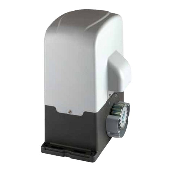
2 PRODUCT DESCRIPTION Models and contents of the package The name REV identifies a series of electromechanical operators for sliding gates with different features as to motor and control board power supply voltage, capacity, mechanical adjustment of force, electronic clutch and built-in limit switch. All automated mo- dels involve the use of advanced control units (NET series) equipped with anti-crushing sensor, built-in 433 MHz radio receiver, speed control and slow down in opening and closing. The REV models are intended primarily for residential / condominium and Semi- intensive/intensive use depending on the duty cycle foreseen for the automation. REV is completed by a set of accessories listed in the “PRODUCT ACCESSORIES” table (page 114). REV is composed of a mechanical gear motor which rotates the driving gear; This gear, coupled to the rack properly installed on the gate, converts the circular motion of the gear motor into rectilinear motion thus allowing the movement of the gate on its own guide. Inspect the “Contents of the Package” (Pic. 1) and compare it with your product for useful consultation during assembly. Transport REV is always delivered packed in boxes that provide adequate protection to the product, however, pay attention to all informa- tion that may be provided on the same box for storage and handling. 3 TECHNICAL DATA OPERATOR REV220 - REV220/M - REV220/RF - REV220/RFM - REV24/F - REV24/M - REV220/IB REV220/RF/IB REV24/IB Motor power supply voltage (V) 230 V ~ ±10% (50/60 Hz) 24 V... -
Page 4: Installation And Assembly
• Tighten the lock nuts of REV in a robust way (Fig. 7) and cover with plastic caps. 4.3 How to unlock the operator Once you open the lock on the handle (protected by a plastic cover), the lever must be turned in the direction shown in Fig 8, at this point the operator is unlocked and the gate, in the absence of other obstacles is free in his movements. The reverse process, turn the lever until it stops and closing of the lock (remember to protect the lock with the proper cover), keeps REV in working condition. 4.4 Limit-switches Adjustment of the limit-switches Some REV models provides a limit-switch whose intervention must be adjusted for each installation. DEA System provides two limit switches cams (Fig. 9) that are installed on the rack of the gate and subsequently regulated in such a way as to ensure the functio- nality and safety distances in opening and closing of the gate. Keep in mind that when the limit switches trigger, the door will move to another 2-3 cm, and it’s therefore suggested to fix the end of stroke brackets at a sufficient distance from the mechanical stops. Adjustment of the magnetic limit switch Attach the mounting brackets to the magnets as shown in Figure 11, making sure to mount the LIGHT BLUE magnet at the closing limit switch, the GREEN magnet at the end of the opening limit switch (Fig. 12). Connect the cable of the magnetic sensor which is colored... -
Page 5: For 24V Models
5.1 ELECTRICAL CONNECTIONS FOR 24V MODELS Execute the wiring following the directions of “Table 1” and diagrams on page 23. WARNING To ensure an appropriate level of electrical safety always keep the 230V power supply cables apart (minimum 4mm in the open or 1 mm through insulation) from low voltage cables (motors power supply, controls, electric locks, aerial and auxiliary circuits power supply), and fasten the latter with appropriate clamps near the terminal boards. WARNING Connect to the power supply 230 V ~± 10% 50 Hz through a multi pole switch or a different device that can ensure multi pole disconnection from the power supply, with a contact opening of 3 mm. WARNING To connect the encoder to the control panel, use only a dedicated cable 3x0,22mm Table 1 “terminal board connections” +24 V power supply output for auxiliary devices 200mA 22 V ~ transformer power supply input 24 V battery power supply or photovoltaic accumulator Green Energy input (follow carefully polarity indications). Operator 1 output Connection of motors metallic parts 10-11 Operator 2 output (if present) 12-13... - Page 6 OPEN GATE WARNING LIGHT 24V 15w N.O. N.C. BLUE...
-
Page 7: Electrical Connections For 230V Models 24
5.2 ELECTRICAL CONNECTIONS FOR 230V MODELS Execute the wiring following the directions of “Table 2” and diagrams on page 25. WARNING To ensure an appropriate level of electrical safety always keep the 230V power supply cables apart (minimum 4mm in the open or 1 mm through insulation) from low voltage cables (motors power supply, controls, electric locks, aerial and auxiliary circuits power supply), and fasten the latter with appropriate clamps near the terminal boards. WARNING Connect to the power supply 230 V ~± 10% 50 Hz through a multi pole switch or a different device that can ensure multi pole disconnection from the power supply, with a contact opening of 3 mm. WARNING To connect the encoder to the control panel, use only a dedicated cable 3x0,22mm Tabella 2 “collegamento alle morsettiere” 230 V ~ ±10% (50/60 Hz) power supply input 3-4-5 Operator 1 output 230 V ~ max 600W 6-7-8 Operator 2 output 230 V ~ max 600W (if present) 9-10 230 V ~ max 150 W output for open gate warning light (if P052=0) or courtesy light (if P052>1) 11-12 Flashing light output 230 V ~ max 40W “Boost” output for electric-lock, max 1 x art. 110 (if P062=0), 24V pulse output, max 5W (if P062=1), 13 (-) - Page 8 OPEN GATE WARNING LIGHT 230V max 150W N.O. N.C. BROWN OMNIPOLAR CIRCUIT BRAKER GRAY POWER SUPPLY BLACK 230V~ 50Hz ±10% 3 x 1,5 mm...
-
Page 9: Standard Programming
6 STANDARD PROGRAMMING Power Supply Give power supply, the display shows the following symbols “ ”, “ ”, “ ” and then “----”. If the control panel has already been programmed and the power fails or is switched off - once power is returned and a START command is given, the position reset procedure is performed (see “rESP” in the table “WORKING STATUS MESSAGES” on page 31. Visualisation of inputs and operations-counter status 1. Press the key for 15 seconds; 2. The display will show respectively: Inputs status (check it’s correct); Total operations counter (* see P064): i.g.: = 3x100* = 3000 operations performed Maintenance operations-counter (* see P065): i.g.: = 5*x500 = 2500 operations remaining before the maintenance intervention request ( manoeuvres-counter disabled) 3. Hold down the key to display a cyclic 3 options, or release the button to exit the parameter. ! IMPORTANT ! Selection type of operators 1. Scroll down the parameters with and keys until you vi-... - Page 10 Selection of direction of motion 1. Scroll down the parameters with and keys until you visualise P063; 2. Access the parameter by pressing the key; 3. Acting on and keys, set: - d000=motor in standard position (on the left of the gap); - d001=motor in inverted position (on the right of the gap); 4. Confirm your choice by pressing the key (di- splay returns again to P063). Warning: The parameter automatically reverses the motors output open/close and any limit switch input open/close.
- Page 11 9.2 Learning 1. Scroll down the parameters with and keys until you visualise P005; 2. Confirm by pressing on the key; 3. When the symbol “ ” appears, press on any key of the transmitter you want to memorize; 4. The display visualizes the number of the transmitter just memorized and then “ ”; 5. Memorize all necessary transmitters repeat- ing this procedure from step 3; 6. Wait 10 seconds before quitting the memo- rization mode, display shows now “----“.
-
Page 12: Advanced Programming
7 ADVANCED PROGRAMMING Here are some added programming procedures relating to remotes memory management and advanced configuration of the control inputs. Deletion of memorized transmitters 1.1 Deletion of all transmitters 1. Scroll down the parameters until you visualize P004; 2. Confirm by pressing on the key; 3. When “ ” is flashing, press the key for a few seconds; 4. Release the key as soon as “ ” stops flashing; 5. All memorized transmitters have been deleted (display shows again P004). - Page 13 3.2 Unlocking access to programming 1. Scroll through the parameters with the buttons and until the display shows P008; 2. Access the parameter by pressing the button 3. The display shows alternately the writing to indicate that the control board is waiting for the transmission of the unlocking code; 4. Within 10 sec. press the CH1 of the “TX Mas- ter”, the display shows before returning to the list of parameters; 5. Access to programming is unlocked. 3.3 Unlocking access to programming and global reset WARNING! This procedure involves the loss of all stored settings.
-
Page 14: Messages Shown On The Display
- Make sure that operators and encoders connections are well done. - Check that jumpers J5 and J9 are well positioned as shown on the electric wiring Operators mouvement not detected. (for 24V only). - If this error appears again, replace the control panel. 9 START-UP The start-up phase is very important to ensure maximum security and compliance to regulations, including all the requirements of EN 12445 standard which establishes the test methods for testing the automation for gates. DEA System reminds that all installation, maintenance, cleaning or repair operations on any part of the system must be performed exclusively by qualified personnel who must be responsible of all texts requie by the eventual risk; 9.1 Installation test The testing operation is essential in order to verify the correct installation of the system. DEA System wants to summarize the proper testing of all the automation in 4 easy steps: • Make sure that you comply strictly as described in paragraph 2 “WARNINGS SUMMARY”; • Test the opening and closing making sure that the movement of the leaf match as expected. We suggest in this regard to perform various tests to assess the smoothness of the gate and defects in assembly or adjustment; • Ensure that all safety devices connected work properly; • Perform the measurement of impact forces in accordance with the standard 12445 to find the setting that ensures compliance with the limits set by the standard EN12453. WARNING Using spare parts not indicated by DEA System and/or incorrect re-assembly can create a risk to people, animals and property and also damage the product. For this reason, always use only the parts indicated by DEA System and scrupulously follow all assembly instructions. 9.2 Unlocking and Manual operation In the event of malfunctions or simple power failure, release the motor (Pic. 8) and perform the operation manually. The knowledge of the unlocking operation is very important, because in times of emergency the lack of timeliness in acting on such a device can be dangerous. WARNING The efficancy and safety of manual operation of the automation is guaranteed by DEA System only if the installation has been installed correctly and with original accessories. -
Page 15: Maintenance
6 months Consult the TROUBLE-SHOOTING” table whenever anoma- checking of release mechanism operation 6 months lies are observed in order to find the solution to the problem and contact DEA System directly whenever the solution required is not electric brake cleaning 6 months provided. TROUBLE-SHOOTING Description Possible solutions When the opening or closing command is activated the The operator is not receiving correct power supply. Check all connections, fuses, and the... - Page 16 PROGRAMMING PROCEDURES INPUTS CONFIGURATION PARAMETERS...
- Page 17 OPERATORS CONFIGURATION OPERATING PARAMETERS PARAMETERS...
- Page 18 OPERATING PARAMETERS...
- Page 19 OPERATING PARAMETERS...
- Page 22 500 - 600...
- Page 24 FCC 1 FCA 1 Finecorsa magnetico di chiusura (azzurro) Finecorsa magnetico di apertura (verde) Closing magnetic limit switch (light blue) Opening magnetic limit switch (green) Fin de course magnétique de fermeture (bleu) Fin de course magnétique d’ouverture (vert) Final de carrera magnético de cierre (azul) Final de carrera magnético de apertura (verde) Fim-de-curso de fecho magnético (azul) Fim-de-curso de abertura magnético (verde)
- Page 25 Tabella “ACCESSORI PRODOTTO”, Table “PRODUCT ACCESSORIES”, Tableau “ACCESSOIRES PRODUITS”, Tabla “ACCESORIOS PRODUCTO”, Tabela “ACESSÓRIOS DO PRODUTO”, Tabell “AKCESORIA DODATKOWE”. Descrizione, Description, Description, Article Descripción, Descrição, Opis Code Cremagliera in NYLON NYLON rack Crémaillère NYLON Cremallera NYLON 619000 Cremalheira NYLON Listwa zębata NYLONOWA Cremagliera ZINCATA 22x22 ZINC PLATED rack 22x22 Crémaillère ZINGUÉE 22x22...
- Page 26 Downee Customer Service (03) 9364 8288 Tech Support See downee.com.au for your state office Telephone: 1800 241 733 Tech Support 1800 241 733 techsupport@downee.com.au Tech Support Hotline: 0419 599 982 downee.com.au Email: techsupport@downee.com.au...
Need help?
Do you have a question about the REV Series and is the answer not in the manual?
Questions and answers