
Subscribe to Our Youtube Channel
Related Manuals for Emerson Digitax ST


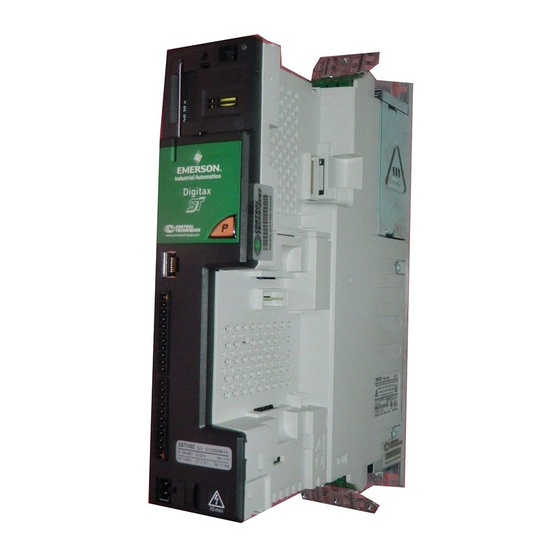
Summary of Contents for Emerson Digitax ST
- Page 1 User Guide AC variable speed drive for servo motors Part Number: 0475-0001-05 Issue: 5...
- Page 2 This may also apply to drives returned from an Emerson Industrial Automation Service Centre or Repair Centre. If there is any doubt please contact the supplier of the product.
- Page 3 How to use this guide This User Guide provides information for operating the drive from start to finish. The information is in logical order, taking the reader from receiving the drive through to fine tuning the performance. NOTE There are specific safety warnings throughout this guide, located in the relevant sections. In addition, Chapter 1 Safety Information on page 6 contains general safety information.
-
Page 4: Table Of Contents
4.15 Encoder connections ...........37 9.24 Advanced features ..........94 4.16 Encoder terminals ..........38 9.25 Advanced cyclic data configuration ....96 4.17 Safe Torque Off ...........42 9.26 Internal shortcuts ..........97 9.27 Quick reference ..........98 Digitax ST User Guide Issue: 5... - Page 5 12.20 Menu 21: Second motor parameters ....164 12.21 Menu 22: Additional Menu 0 set-up ....165 12.22 Advanced features ..........166 Technical Data ........173 13.1 Drive technical data ..........173 13.2 Optional external EMC filters ......182 13.3 Overall EMC filter dimensions ......182 Digitax ST User Guide Issue: 5...
-
Page 6: Safety Information
The system designer is responsible for ensuring that the The STOP function does not remove dangerous voltages from the drive, complete system is safe and designed correctly according to the the motor or any external option units. relevant safety standards. Digitax ST User Guide Issue: 5... - Page 7 If the drive has failed in a manner that causes the display to go blank immediately, it is possible the capacitors will not be discharged. In this case, consult Emerson Industrial Automation or their authorized distributor.
-
Page 8: Product Information
200 % overload capability. When the Plus drives, an export feature is available that allows the user to import Digitax ST 120x is used with a single phase supply it is possible to applications into SYPTPro for further development. -
Page 9: Drive Model Numbers
Please read the manual before connecting Electric Shock Risk: Wait 10 mins between disconnecting supply and accessing terminals RoHS S/N: 3000005001 Serial IND. CONTROL Approvals EQUIPMENT Compliant number UL file: E171230 N1652 Designed in the U.K. Made in China Digitax ST User Guide Issue: 5... -
Page 10: Features Of The Drive
The drive is supplied with a SMARTCARD installed. Do not remove until after first power-up, as defaults are stored on the SMARTCARD. Be aware of possible live terminals when inserting the SMARTCARD. WARNING Static precautions must be taken when removing the Solutions Module slot covers. CAUTION Digitax ST User Guide Issue: 5... -
Page 11: Options
Diagnostics Information information installation installation started parameters motor interface Operation parameters Data information Options Figure 2-4 Options available with Digitax ST DST Keypad Internal braking SM-Keypad Plus resistor SMARTCARD* External footprint/ bookcase EMC filter Fieldbus CT Comms Automation cable I/O Expansion... - Page 12 2 x Analog outputs (current modes) Protected 4 x Digital input / outputs, 3 x Digital inputs, 2 x Relay outputs Applications Processor Automation Golden SM-Register processor for running position capture functionality with (Applications) brown CTNet support. Digitax ST User Guide Issue: 5...
- Page 13 Brown Red SM-EtherCAT EtherCAT adapter for communications with the drive SLM interface The SM-SLM allows SLM feedback to be connected directly to the Digitax ST drive and allows operation in either of the Orange SM-SLM following modes: • Encoder only mode •...
-
Page 14: Items Supplied With The Drive
An accessory box containing the items illustrated in Figure 2-5 is also provided. Figure 2-5 Accessory box contents Control connectors Digitax ST EtherCAT additional connector Digitax ST Plus additional connectors Relay connector Grounding bracket Ground screws Cable guides Ground screws Digitax ST User Guide Issue: 5... -
Page 15: Mechanical Installation
If the drive has failed in a manner that causes the display to go blank immediately, it is possible the capacitors will not be discharged. In this case, consult Emerson Industrial Automation or their authorized distributor. Drive Competence of the installer The drive must be installed by professional assemblers who are familiar with the requirements for safety and EMC. -
Page 16: Solutions Module / Keypad Installation / Removal
Figure 3-3 Installation of a Solutions Module NOTE The protective tab from the Solutions Module slot must be removed before attempting to install a Solutions Module. Be aware of possible live terminals when installing the keypad. WARNING Digitax ST User Guide Issue: 5... -
Page 17: Drive Dimensions
The labels should be removed before first drive. power up. Digitax ST User Guide Issue: 5... -
Page 18: External Emc Filter Rating
Data information Digitax ST can be mounted using a DIN rail, either fixed at the top or the bottom of the drive (as illustrated in Figure ). Two screws are required to fix the drive to the backplate at the opposite end to the DIN rail. -
Page 19: Optional Braking Resistor
If using an external braking resistor, the following Warning must be adhered to: Braking resistor: High temperatures and overload protection Braking resistors can reach high temperatures. Locate braking resistors so that damage cannot result. Use cable having insulation capable of withstanding the high temperatures. WARNING Digitax ST User Guide Issue: 5... -
Page 20: Terminal Torque Settings
Electrical Screw Ensure all screw terminals remain tight connections Crimp Ensure all crimp terminals remains tight – check for any terminals discoloration which could indicate overheating Cables Check all cables for signs of damage Digitax ST User Guide Issue: 5... -
Page 21: Electrical Installation
If the drive has failed in a manner that causes the display to go blank immediately, it is possible the capacitors will not be discharged. In this case, consult Emerson Industrial Automation or their authorized distributor. Equipment supplied by plug and socket... -
Page 22: Power Terminal Connections
* When using a 200 V drive on a single phase supply, the live and neutral conductors can be connected to any of the AC connections on the drive. ** This is not required if the optional internal braking resistor is used. Digitax ST User Guide Issue: 5... -
Page 23: Ground Connections
IV to category III. --------- - × ------ - × ----------- - 2πfI Where: I = drive rated input current (A) L = inductance (H) f = supply frequency (Hz) V = voltage between lines Digitax ST User Guide Issue: 5... -
Page 24: Dc Bus Design
Condition drives in parallel. In addition to this If the total rated bus power required exceeds the capability of 1 x Digitax ST rectifier then two or more Digitax Undervoltage trip level ST's can be connected with the AC & DC in parallel. If the AC supply is... -
Page 25: Ratings
Use 105 °C (221 °F) (UL 60/75 °C temp rise) PVC-insulated cable with A fuse or other protection must be included in all live connections to the copper conductors having a suitable voltage rating, for the following AC supply. power connections: Digitax ST User Guide Issue: 5... -
Page 26: Braking
Figure 4-3 Cable construction influencing the capacitance • The power rating of the resistor is only 50 W The internal braking resistor for Digitax ST is installed with a thermistor which must be connected to the drive whenever the internal braking resistor in installed. -
Page 27: Ground Leakage
Failure to observe the following information may damage the resistor. DST1402 The drive’s software contains an overload protection DST1403 CAUTION function for a braking resistor. On Digitax ST this function is DST1404 enabled at default to protect the internally mounted resistor. 21.7 DST1405 12.2 Below are the parameter settings. -
Page 28: Emc (Electromagnetic Compatibility)
• A shielded control cable, with shield clamped to the grounded metal panel via the grounding bracket. NOTE It is not necessary to remove the external EMC filter when using an IT supply. Digitax ST User Guide Issue: 5... - Page 29 AC supply contactor and External fuses or MCB controller Signal cables Plan for all signal cables to be routed at least 300mm (12in) from the drive and any power cable Digitax ST User Guide Issue: 5...
-
Page 30: Internal And External Conducted Emissions Conformity
IEC61000-6-2 Generic immunity standard for the EN61000-6- Complies industrial environment 2:2005 EN 61800- Product standard for adjustable Meets immunity 3:2004 speed power drive systems requirements for first and IEC61800-3 (immunity requirements) second environments Digitax ST User Guide Issue: 5... -
Page 31: Serial Communications Connections
Restricted distribution is defined as a mode of sales distribution in which the manufacturer restricts the supply of equipment to suppliers, customers or users who separately or jointly have technical competence in the EMC requirements of the application of drives. Digitax ST User Guide Issue: 5... -
Page 32: Control Connections
The 120 Ω Termination resistor network should be made up entirely of Digitax ST drives. RX TX If the CT Comms Cable is to be used, then pin 6 (TX enable) should be... - Page 33 Terminals 3 and 11 should be used for connecting the 0V common of analog signals and terminals 21, 23 and 30 for digital signals. This is to prevent small voltage drops in the terminal connections causing inaccuracies in the analog signals. Digitax ST User Guide Issue: 5...
-
Page 34: Control Terminals
II) For control terminal specification, refer to Chapter 4.14.1 Control terminal specification on page 35. NOTE If Terminal 31 is used as a Safe Torque Off function, the cable must be shielded or segregated. Digitax ST User Guide Issue: 5... - Page 35 Pr 1.36, Sampling period Pr 1.37 or Pr 3.22. Pr 1.37, Pr 3.22 or Pr 4.08. T8 analog input 3 has a parallel connection to terminal 15 of the drive input encoder connector. Digitax ST User Guide Issue: 5...
- Page 36 Pr 8.40. 250μs with devices Sample / Update period destinations as Pr 6.35 or Pr 6.36. 600μs with destination as Pr 6.29. 4ms in all other cases. 0V common Common connection for all external Function devices Digitax ST User Guide Issue: 5...
-
Page 37: Encoder Connections
0V alone at both drive and encoder end, when required. NOTE Ensure that feedback cables are kept as far away as possible from power cables and avoid parallel routing. Digitax ST User Guide Issue: 5... -
Page 38: Encoder Terminals
** The U, V & W commutation signals are required with an incremental type encoder when used with a servo motor. The UVW commutation Digitax ST User Guide Issue: 5... - Page 39 <2 unit loads 120 Ω (switchable) Line termination components Working common mode range +12 V to –7 V Absolute maximum applied ±25 V voltage relative to 0V Absolute maximum applied ±25 V differential voltage Digitax ST User Guide Issue: 5...
- Page 40 If a SINCOS is used as the source the buffered output is derived from the zero crossings of the sine waves and does not include interpolated For the SinCos encoder to be compatible with Digitax ST, the output information. The buffered encoder output provides an output with signals from the encoder must be a 1 V peak to peak differential voltage minimal delay from the drive encoder input (maximum delay is 0.5 µs).
- Page 41 0V common 0V common connection for digital I/O 4.16.3 Digitax ST Plus additional connections Input 1 Digital input 1 Figure 4-18 Digitax ST Plus terminals view Input 2 Digital input 2 Input 3 Digital input 3 Input 4 Digital input 4...
-
Page 42: Safe Torque Off
Safe Torque Off Engineering Guide available for download from system. The system must be subject to a risk assessment to http://www.emersonindustrial.com/en-EN/controltechniques/downloads/ confirm that the residual risk of an unsafe event is at an userguidesandsoftware/Pages/downloads.aspx. acceptable level for the application. Digitax ST User Guide Issue: 5... -
Page 43: Getting Started
Users who wish to maximize performance of the Digitax ST Indexer or There are six user interfaces available for the various drive variants. the Digitax ST Plus. SYPTPro allows the user to program in a choice of three languages, with a real-time multi-tasking environment •... -
Page 44: Keypad Operation
Understanding the display There are two keypads available for the Digitax ST. The Digitax ST Keypad has an LED display and the SM-Keypad Plus has an LCD display. The Digitax ST Keypad can be installed to the drive and the SM -Keypad Plus is remotely mounted on an enclosure door. - Page 45 When changing between menus the drive remembers which parameter was last viewed in a particular menu and thus displays that parameter. Digitax ST User Guide Issue: 5...
- Page 46 Carry out a drive reset through serial communications by setting The Access Level can be changed through the keypad even if the User Pr 10.38 to 100 (ensure that Pr. xx.00 returns to 0). Security has been set. Digitax ST User Guide Issue: 5...
-
Page 47: Displaying Parameters With Non-Default Values Only
PC or PLC if required. Therefore, it is (except Pr 0.49 and Pr 11.44 possible to control the drive entirely by serial communications without the need for a -keypad or other control cabling. The Digitax ST supports Pr 0.00 Pr 1.00 .... Pr 21.00 Pr 22.00 two protocols selected by parameter configuration: Pr 0.01... - Page 48 When the ANSI protocol is used the first digit is the group and the second digit is the address within a group. The maximum permitted group number is 9 and the maximum permitted address within a group is Digitax ST User Guide Issue: 5...
-
Page 49: Basic Parameters
L1 (0), L2 (1), Loc (2) RW Txt PT US 0.50 Software version { 11.29 } 1.00 to 99.99 RO Uni NC PT 0.51 Action on trip detection { 10.37 } 0 to 15 Digitax ST User Guide Issue: 5... - Page 50 Protected: cannot be used as a destination. User save: parameter saved in drive EEPROM when the user initiates a parameter save. Power-down save: parameter automatically saved in drive EEPROM when the under volts (UV) trip occurs. Digitax ST User Guide Issue: 5...
- Page 51 Safety Product Mechanical Electrical Getting Basic Running the EtherCAT SMARTCARD Onboard Advanced Technical UL listing Optimization Diagnostics installation Information information installation started parameters motor interface Operation parameters Data information Digitax ST User Guide Issue: 5...
- Page 52 A1.Pr Preset reference selectors A2.Pr Preset reference selectors Preset reference selectors Local/Remote Local/Remote Input Read-write (RW) 0.XX terminals parameter Read-only (RO) Output 0.XX parameter terminals The parameters are all shown in their default settings Digitax ST User Guide Issue: 5...
- Page 53 Speed-loop 0.15 0.09 derivative gain Ramp mode selector Motor speed 0.10 Power stage PWM switching 0.41 frequency Drive encoder Drive encoder 0.11 0.27 position Overspeed 0.26 threshold 15 way sub-D connector Resistor optional Digitax ST User Guide Issue: 5...
-
Page 54: Full Descriptions
0 to 5 A1.A2 (0) Transfer the user program in the SM-Applications Modules 17yyy And Motion Processors (Digitax ST Plus and Indexer) to data Use Pr 0.05 to select the required speed reference as follows: block number yyy on a SMARTCARD Setting... - Page 55 65,535. There are 65,536 units to one mechanical revolution. of which changes the demanded load current in the motor. As the controller regulates the DC bus voltage, the motor deceleration increases as the speed approaches zero speed. When the motor deceleration rate Digitax ST User Guide Issue: 5...
- Page 56 In modes 2 & 4 the analog input level goes to 0.0 % if the input current Pr 0.22 determines whether the reference is uni-polar or bi-polar as falls below 4 mA. follows: Pr 0.22 Function Unipolar speed/reference Bipolar speed/reference Digitax ST User Guide Issue: 5...
- Page 57 Modbus RTU protocol, but with an SM-Keypad Plus only This setting is used for disabling communications access when the SM- Keypad Plus is used as a hardware key. See the Keypad Plus User Guide for more details. Digitax ST User Guide Issue: 5...
- Page 58 ‘O.ht1’ trip. Every second the drive will attempt to restore the measurement test should be performed separately to a short low speed switching frequency to the level set in Pr 0.41. or normal low speed autotune. Digitax ST User Guide Issue: 5...
- Page 59 Enter the name-plate value for the motor rated current. disabled in 200 V drives only. Disable braking resistor temperature monitoring failure detection Digitax ST have an internal user install braking resistor with a thermistor 0.48 {11.31} User drive mode to detect overheating of the resistor. If the resistor is not installed the trip can be disabled by setting Pr 10.37 (0.51) to 8.
-
Page 60: Running The Motor
SINCOS encoder (with Stegmann Hiperface, EnDat or SSI communications protocols) • EnDat absolute encoder For Solutions Module terminal information see section 12.15 Menus 15 and 16: Solutions Module set-up on page 159 or the appropriate Solutions Module Option User Guide. Digitax ST User Guide Issue: 5... - Page 61 4500-0096 Comms cable Serial Comms Isolated serial Serial User Interface comms lead communications port Polarized signal connections SAFE TORQUE OFF(drive Encoder connector enable - T31) U V W 15 way D-type U V W Digitax ST User Guide Issue: 5...
- Page 62 Internal terminal screws (17.7 Ib in) braking * Torque tolerance = 10% resistor (optional) Polarized signal connections SAFE TORQUE OFF(drive Encoder connector enable - T31) U V W 15 way D-type U V W Digitax ST User Guide Issue: 5...
- Page 63 (optional) terminal screws (17.7 Ib in) input * Torque tolerance = 10% Polarized signal connections forward reverse SAFE TORQUE OFF(drive Encoder connector enable - T31) U V W 15 way D-type U V W Digitax ST User Guide Issue: 5...
-
Page 64: Quick Start Set-Up
0.04 Digitax ST is able to perform a short low speed, a normal low speed or a minimal movement autotune. The motor must be at a standstill before an autotune is enabled. A normal low speed autotune will measure the encoder phase offset angle and calculate the current gains. -
Page 65: Setting Up A Feedback Device
Setting up a feedback device This section shows the parameter settings which must be made to use each of the compatible encoder types with Digitax ST. For more information on the parameters listed here please refer to the Advanced User Guide. - Page 66 Absolute Sincos encoder with Hiperface or EnDat serial communications, or Absolute EnDat communications only encoder The Digitax ST is compatible with the following Hiperface encoders: SCS 60/70, SCM 60/70, SRS 50/60, SRM 50/60, SHS 170, LINCODER, SCS-KIT 101, SKS36, SKM36, SEK-53.
- Page 67 Initialization causes an encoder with communications to be re-initialized and auto-configuration to be performed if selected. After initialization Ab.SErVO, Fd.SErVO and Fr.SErVO encoders will use the UVW commutations signals to give position feedback for the first 120° (electrical) of rotation when the motor is restarted. Digitax ST User Guide Issue: 5...
-
Page 68: Setting Up A Buffered Encoder Output
Data information Setting up a buffered encoder output The Digitax ST has a buffered encoder output, which derives its position from the drive encoder input. The buffered encoder output is sourced from the drive encoder input and can be any incremental type or any SINCOS type. -
Page 69: Optimization
The drive can be put in to a controlled disable condition by removing the Safe Torque Off signal from terminal 31, setting the drive enable parameter Pr 6.15 to OFF (0) or disabling the drive via the control word (Pr 6.42 & Pr 6.43). Digitax ST User Guide Issue: 5... - Page 70 In some applications where it is necessary for the reference frame used by the drive to dynamically follow the flux very closely (i.e. high speed closed-loop induction motor applications) the integral gain may need to have a significantly higher value. Digitax ST User Guide Issue: 5...
- Page 71 Pr 5.32 - Motor torque per amp (Kt). Pr 3.18 - Motor and load inertia The drive can be made to measure the motor and load inertia by performing an inertia measurement autotune (see Autotune Pr 0.40, earlier in this table). Digitax ST User Guide Issue: 5...
-
Page 72: Ethercat Interface
EtherCAT interface information Network topology 9.3.1 Bus media Emerson Industrial Automation recommend implementing daisy chaining The EtherCAT interface incorporates two 100 BASE-TX RJ45 interfaces. on EtherCAT networks (see Figure 9-2). Other Ethernet network 9.3.2 Cabling considerations topologies can be used but care must be taken to ensure that the system To ensure long-term reliability it is recommended that any cables used to still operates within the constraints specified by the designer. - Page 73 Generic support is available • Index: 0x2000 + menu number through your supplier or local Emerson Industrial Automation centre. • Sub-index: 0x00 + parameter number Before contacting your supplier or local Emerson Industrial Automation •...
-
Page 74: Quick Start Flowchart
Values written to parameters over RxPDOs should now be viewable using the drive’s keypad so long as the master has put the slave into the operational state; also, parameter values changed using the drive keypad will be updated on the master. Digitax ST User Guide Issue: 5... -
Page 75: Saving Parameters To The Drive
Sub-index 0 for any menu will return the highest sub-index available for the object (i.e. the highest parameter number). Pr 17.00 in any drive can only be accessed as Pr 61. 01 (0x203D, sub-index changes to 1). NOTE The following SDO services are supported: Digitax ST User Guide Issue: 5... -
Page 76: Canopen Over Ethercat (Coe)
<default> Description: <description> This value will depend on the drive operating mode and/or type. On a Digitax ST, bit 17 will be set, while bits 16 and For entries having sub-indices 24 will be cleared. Table 9-10 Object description format with sub-indices Table 9-12 Identity object <index>... - Page 77 (each representing an object Bits 8 to 15: Sub-index of the mapped object. mapped to a PDO) defined in the XML configuration file. Bits 16 to 31: Index of the mapped object. Digitax ST User Guide Issue: 5...
- Page 78 Bits 0 to 7: Length of the mapped object in bits, e.g. a 32- Description: bit parameter would have a length of 32 or 0x20. Bits 8 to 15: Sub-index of the mapped object. Bits 16 to 31: Index of the mapped object. Digitax ST User Guide Issue: 5...
- Page 79 Sync manager 0 PDO assignment Sub-index 0 Access: RO Range: N/A Size: 1 byte Unit: N/A Default: Number of assigned PDOs. The mailbox received sync Description: manager can never have PDOs assigned to it. Digitax ST User Guide Issue: 5...
-
Page 80: Ethernet Over Ethercat (Eoe)
Figure 9-7 EoE Subnet mask format This protocol allows standard Ethernet messages and protocols to be tunnelled through the EtherCAT network. This provides users with the SM-EtherCAT EoE Subnet mask possibility of connecting to the Emerson Industrial Automation PC Tools subnet subnet subnet... -
Page 81: Drive Profile (Dsp-402) Support
EtherCAT interface. In the default state the primary NOTE: Automatic transition to Enable operation state after executing SWITCHED ON state functionality. interface will be provided by the drive. Pr 17.37 = OFF (default): Digitax ST User Guide Issue: 5... - Page 82 ‘SWITCH ON DISABLED’. When in the ‘OPERATION ENABLED’ or ‘QUICK STOP ACTIVE’ states it is not possible to change the mode_of_operation object. This is to ensure that the motor is stopped before changing the operation mode. Digitax ST User Guide Issue: 5...
- Page 83 These values are set once and not continuously forced. They are not reset when leaving the Operational state. In addition, the option starts to write parameters implicitly mapped by the CoE profiles, when moving to the Operational state. Digitax ST User Guide Issue: 5...
- Page 84 This object is used to control what action is performed if No mode change Description: there is a transition from the Operation Enabled state to vl velocity mode the Switched On state. Profile torque mode Homing mode Interpolated position mode Cyclic sync position mode Digitax ST User Guide Issue: 5...
- Page 85 It is also necessary to re-scale velocity limit values with the new factor. It is not possible to change these values cyclically (i.e. by mapping PDOs to them). Digitax ST User Guide Issue: 5...
- Page 86 Position_actual_value Range: 0 to Access: RO Size: signed 32 Unit: N/A 0xFFFFFFFF Default: This read only object provides the actual value of the Description: position feedback device. The value is given in internal units. Digitax ST User Guide Issue: 5...
-
Page 87: Interpolated Position Mode
On each interpolator time period, a value is read from this buffer. The correct number of data points for a specific interpolation mode are stored internally. When a new position command is loaded in, the oldest position command in the data set is discarded. Digitax ST User Guide Issue: 5... -
Page 88: Vl Velocity Mode
This object is used to configure the minimum and maximum velocity. which the system can operate. The value is given in rpm if the vl_dimension_factor has the value of 1, otherwise the value is in user units. Digitax ST User Guide Issue: 5... - Page 89 Example: To decelerate by 800 rpm in 10 s, possible values for delta speed and delta time are 8000 and 100 respectively. vl velocity deceleration = delta speed / delta time Digitax ST User Guide Issue: 5...
-
Page 90: Profile Torque Mode
(also for quick stop option codes 2 and 6 the 0x6049 vl_velocity_deceleration object will be used). Table 9-90 shows the objects that are supported: Table 9-90 Profile torque mode supported objects Index Name 0x6071 Target_torque 0x6075 Motor_rated_current 0x6078 Current_actual_value 0x6087 Torque_slope Digitax ST User Guide Issue: 5... -
Page 91: Homing Mode
(here: low). The position of home shall be at the first index pulse to the left of the position where the positive limit switch becomes inactive. Digitax ST User Guide Issue: 5... - Page 92 For example methods 19 and Homing procedure was completed successfully. 20 are similar to methods 3 and 4 as shown in Figure 9-17. Homing error occurred, velocity is not 0. Homing error occurred, velocity is 0. Reserved. Digitax ST User Guide Issue: 5...
- Page 93 All subsequent absolute moves shall be taken relative to this new zero position. This is illustrated in Figure 9-19. The value of this object shall be given in user- Digitax ST User Guide Issue: 5...
-
Page 94: Cyclic Sync Position Mode
0x60B1 Velocity offset This object provides the offset for the velocity value. The offset is given in user defined velocity units. In cyclic synchronous position mode this object contains the input value for velocity feed forward. Digitax ST User Guide Issue: 5... - Page 95 0 to 2 The EtherCAT interface should try to become Access synchronization master to clocks in other EtherCAT interfaces. Slave. The EtherCAT interface should become a synchronization slave to clocks in another EtherCAT interfaces. Digitax ST User Guide Issue: 5...
-
Page 96: Advanced Cyclic Data Configuration
EtherCAT interface error sub-code task which occurs upon a sync manager access. Default Pr 61.49 Range 0 to 255 Access This parameter provides more detailed information of the cause of the current EtherCAT interface error. Digitax ST User Guide Issue: 5... -
Page 97: Internal Shortcuts
1_Critical+90 task (Default). This is the task that commences 90μs after the critical task start, and finishes before the next critical task. 2 – Sync Manager task (default). This is the AL event task which occurs upon a sync manager access. Digitax ST User Guide Issue: 5... -
Page 98: Quick Reference
Section 9.20.8 on page 89 slope of the deceleration ramp for quick stop. This object is used to configure the numerator and denominator of 0x604B vl_setpoint factor Section 9.20.9 on page 89 the vl_setpoint_factor. Digitax ST User Guide Issue: 5... - Page 99 0x60C1 Interpolation data_record This object is used to specify the target position. Section 9.19.2 on page 87 0x60C2 Interpolation time_period The number of time units between interpolator re-starts. Section 9.19.3 on page 87 Digitax ST User Guide Issue: 5...
- Page 100 Section 14.14 on page 203 Pr 17.50 EtherCAT interface error code 0 to 255 Section 14.10 on page 201 Pr 17.51 EtherCAT interface firmware - subversion 0 to 99 Section 14.4.2 on page 199 Digitax ST User Guide Issue: 5...
-
Page 101: Smartcard Operation
The encoder phase angles in Pr 3.25 and Pr 21.20 are copied to the SMARTCARD when using any of the SMARTCARD transfer methods. WARNING Figure 10-1 Installation of the SMARTCARD NOTE When inserting the SMARTCARD, always ensure that ST SP0 arrow points upwards. Be aware of possible live terminals when inserting the SMARTCARD. WARNING Digitax ST User Guide Issue: 5... -
Page 102: Transferring Data
Data transfer to or from the SMARTCARD is indicated by one the 9666 Set SMARTCARD warning suppression flag following: 9777 Clear SMARTCARD read-only flag • Digitax ST: The decimal point after the fourth digit in the upper 9888 Set SMARTCARD read-only flag display will flash. 9999 Erase SMARTCARD •... - Page 103 EEPROM, i.e. this is equivalent to writing 6001 to Pr xx.00. All drive to behave in the same way at power-up as a file created with boot SMARTCARD trips apply. Once the parameters are successfully copied Digitax ST User Guide Issue: 5...
-
Page 104: Data Block Header Information
17yyy And Motion Processors (Digitax ST Plus and Indexer) to data parameter (Pr 11.40) shows the product identifier (2 = Digitax ST). block number yyy on a SMARTCARD If there is no data on the card Pr 11.37 can only have values of 0 or 1000... - Page 105 (0) = Inactive rEAd (1) = Read parameter set from the SMARTCARD Prog (2) = Programming a parameter set to the SMARTCARD Auto (3) = Auto save boot (4) = Boot mode Digitax ST User Guide Issue: 5...
-
Page 106: Smartcard Trips
An error has occurred when attempting to transfer a user program from a Solutions Module to a SMARTCARD and vice C.SLX versa See section 10.2.8 SM-Applications Modules And Motion Processors program to/from SMARTCARD transfer system on page 104 172,173,174 for more information. Digitax ST User Guide Issue: 5... - Page 107 10.2.4 Booting up For further information, please refer to section from the SMARTCARD on every power up (Pr 11.42 = 10.2.3 Auto saving parameter changes (Pr 11.42 = Auto boot (4)) . (3)) . Digitax ST User Guide Issue: 5...
-
Page 108: Onboard Plc
As the drive's processor becomes The Digitax ST has the ability to store and execute a 4KB Onboard PLC more heavily loaded, less time is spent executing the program. -
Page 109: Onboard Plc Trips
Check program number of times an Onboard PLC program download has taken place Onboard PLC program attempted write to a read- and is 0 on dispatch from the factory. The Digitax ST is rated for one UP ro only parameter hundred ladder program downloads. -
Page 110: Advanced Parameters
General drive set-up Threshold detectors and variable selectors Position control User PID controller 15, 16 Solutions Module slots Digitax ST indexer/plus parameters Application menu 1 Application menu 2 Application menu 3 Second motor parameters Additional Menu 0 set-up Default abbreviations: EUR>... - Page 111 Line power supply loss 6.03 10.15 10.16 5.05 Local position reference 13.20 to 13.23 Logic function 1 9.01 9.04 9.05 9.06 9.07 9.08 9.09 9.10 Logic function 2 9.02 9.14 9.15 9.16 9.17 9.18 9.19 9.20 Digitax ST User Guide Issue Number: 5...
- Page 112 Velocity feed forward 1.39 1.40 Voltage controller 5.31 Voltage mode 5.14 5.17 Voltage rating 11.33 5.09 5.05 Voltage supply 6.44 6.46 5.05 Warning 10.19 10.12 10.17 10.18 10.40 Zero speed indicator bit 3.05 10.03 Digitax ST User Guide Issue Number: 5...
- Page 113 Pr 5.07 is replaced with Pr 21.07 and Pr 5.10 is replaced with Pr 21.10. Maximum torque producing current TORQUE_PROD_CURRENT_MAX This is used as a maximum for torque and torque producing current parameters. It is [1000.0%] MOTOR1_CURRENT_LIMIT_MAX or MOTOR2_CURRENT_LIMIT_MAX depending on which motor map is currently active. Digitax ST User Guide Issue Number: 5...
- Page 114 AC output voltage, maximum controlled current and unity power factor. Therefore POWER_MAX = √3 x AC_VOLTAGE_MAX x DRIVE_CURRENT_MAX The values given in square brackets indicate the absolute maximum value allowed for the variable maximum. Digitax ST User Guide Issue Number: 5...
- Page 115 Safety Product Mechanical Electrical Getting Basic Running the EtherCAT SMARTCARD Onboard Advanced Technical UL listing Optimization Diagnostics installation Information information installation started parameters motor interface Operation parameters Data information Digitax ST User Guide Issue Number: 5...
-
Page 116: Menu 1: Speed Reference
Read-only (RO) Output 0.XX 1.18 parameter Memory terminals 1.19 Precision The parameters are all shown in their default settings reference trim *For more information, refer to section 12.22.1 Reference modes on page 166 Digitax ST User Guide Issue Number: 5... - Page 117 [1.06] Skip Skip Skip speed 1 speed 2 speed 3 Velocity feed-forward 1.05 1.30 1.32 1.34 [1.06] reference Skip speed Skip speed Skip speed reference band 1 band 2 band 3 [1.06] [1.07] Digitax ST User Guide Issue Number: 5...
- Page 118 (0), LASt (1), PrS1 (2) rESEt (0) RW Txt mode reference RW Read / Write Read only Unipolar Bi-polar Bit parameter Text string Filtered Destination Not copied Rating dependent Protected User save Power down save Digitax ST User Guide Issue Number: 5...
- Page 119 Safety Product Mechanical Electrical Getting Basic Running the EtherCAT SMARTCARD Onboard Advanced Technical UL listing Optimization Diagnostics installation Information information installation started parameters motor interface Operation parameters Data information Digitax ST User Guide Issue Number: 5...
-
Page 120: Menu 2: Ramps
2.03 Pre-ramp speed Ramp mode 1.03 2.04 reference select* *For more information, refer to section 12.22.2 Braking Modes on page 167. **For more information, refer to section 12.22.3 S ramps on page 167. Digitax ST User Guide Issue Number: 5... - Page 121 1.13 indicator Forward Reverse Decel. rate Decel. rate Ramp enable 2.02 Deceleration Post-ramp Ramp control reference 2.06 S-Ramp enable** 2.01 S-Ramp acceleration 2.07 limit 2.08 Standard ramp voltage* 2.38 d/dt Inertia compensation torque Digitax ST User Guide Issue Number: 5...
- Page 122 2.38 Inertia compensation torque ± 1,000.0 % NC PT RW Read / Write Read only Unipolar Bi-polar Bit parameter Text string Filtered Destination Not copied Rating dependent Protected User save Power down save Digitax ST User Guide Issue Number: 5...
- Page 123 Safety Product Mechanical Electrical Getting Basic Running the EtherCAT SMARTCARD Onboard Advanced Technical UL listing Optimization Diagnostics installation Information information installation started parameters motor interface Operation parameters Data information Digitax ST User Guide Issue Number: 5...
-
Page 124: Menu 3: Speed Feedback And Control
3.54 15 way sub-D Ratio connector numerator 3.52 Ab.L Fb.L 0V common **If Ab encoder voltage is greater than 5 V, then the termination resistors must be disabled Pr 3.39 to 0. NOTE Digitax ST User Guide Issue Number: 5... - Page 125 Above at-speed 3.07 Absolute at-speed window indicator detect mode At speed upper limit Input Read-write (RW) 0.XX terminals parameter Read-only (RO) Output 0.XX parameter terminals The parameters are all shown at their default settings Digitax ST User Guide Issue Number: 5...
- Page 126 The encoder phase angles in Pr 3.25 and Pr 21.20 are copied **If Ab encoder voltage is greater than 5 V, then the termination resistors to the SMARTCARD when using any of the SMARTCARD must be disabled Pr 3.39 to 0. transfer methods. WARNING Digitax ST User Guide Issue Number: 5...
-
Page 127: Menu 4: Torque And Current Control
The parameters are all shown at their default settings *For more information, refer to section 12.22.4 Torque modes on page 168. Digitax ST User Guide Issue Number: 5... - Page 128 OFF (0) or On (1) OFF (0) RW Bit mode RW Read / Write Read only Unipolar Bi-polar Bit parameter Text string Filtered Destination Not copied Rating dependent Protected User save Power down save Digitax ST User Guide Issue Number: 5...
- Page 129 Safety Product Mechanical Electrical Getting Basic Running the EtherCAT SMARTCARD Onboard Advanced Technical UL listing Optimization Diagnostics installation Information information installation started parameters motor interface Operation parameters Data information Digitax ST User Guide Issue Number: 5...
-
Page 130: Menu 5: Motor Control
5.12 Auto-tune High dynamic performance enable 5.26 Voltage controller gain 5.31 Input Read-write (RW) 0.XX terminals parameter Read-only (RO) Output 0.XX parameter terminals The parameters are all shown at their default settings Digitax ST User Guide Issue Number: 5... - Page 131 Output 5.02 Field gain voltage 5.21 reduction Output High speed power 5.22 servo mode enable 5.03 Power calculation (V x 1) Motor current Motor active magnitude current 4.01 4.02 4.17 Reactive current Digitax ST User Guide Issue Number: 5...
- Page 132 5.39 0 to 3 RW Uni test pulse length RW Read / Write Read only Unipolar Bi-polar Bit parameter Text string Filtered Destination Not copied Rating dependent Protected User save Power down save Digitax ST User Guide Issue Number: 5...
-
Page 133: Menu 6: Sequencer And Clock
DC link voltage 5.05 Drive power supply monitor Active supply 6.44 Low voltage supply Input Read-write (RW) 0.XX terminals parameter Read-only (RO) Output 0.XX parameter terminals The parameters are all shown at their default settings Digitax ST User Guide Issue Number: 5... - Page 134 *For more information, refer to section 12.22.5 Stop modes on page 169. **For more information, refer to section 12.22.6 Line power supply loss modes on page 169. ***For more information, refer to section 12.22.7 Start / stop logic modes on page 170. Digitax ST User Guide Issue Number: 5...
-
Page 135: Menu 7: Analog I/O
Motor active ??.?? current Read-only (RO) Output 0.XX 7.23 7.24 4.02 parameter terminals Analog Analog ??.?? output 2 output 2 The parameters are all shown at their default settings scaling mode selector Digitax ST User Guide Issue Number: 5... - Page 136 Power circuit temperature 3 ° 7.36 -128 to 127 NC PT (Rectifier) RW Read / Write Read only Unipolar Bi-polar Bit parameter Text string Filtered Destination Not copied Rating dependent Protected User save Power down save Digitax ST User Guide Issue Number: 5...
- Page 137 Safety Product Mechanical Electrical Getting Basic Running the EtherCAT SMARTCARD Onboard Advanced Technical UL listing Optimization Diagnostics installation Information information installation started parameters motor interface Operation parameters Data information Digitax ST User Guide Issue Number: 5...
-
Page 138: Menu 8: Digital I/O
T26 digital 6.04 8.23 I/O 3 source/ Start/stop destination logic select 8.29 8.30 T26 digital 8.13 I/O polarity Open collector unprotected I/O 3 invert output select parameter ??.?? Run forward 6.30 x(-1) ??.?? Digitax ST User Guide Issue Number: 5... - Page 139 This logic diagram applies only when all 8.17 8.27 parameters are at their default settings Any bit parameter Relay Drive state ??.?? 10.01 8.07 ??.?? x(-1) *For more information, please refer to 12.22.1Reference modes on page 166. Digitax ST User Guide Issue Number: 5...
- Page 140 OFF (0) or On (1) OFF (0) RW Bit RW Read / Write Read only Unipolar Bi-polar Bit parameter Text string Filtered Destination Not copied Rating dependent Protected User save Power down save Digitax ST User Guide Issue Number: 5...
-
Page 141: Menu 9: Programmable Logic, Motorized Pot, Binary Sum And Timers
??.?? input-2 invert delay ??.?? ??.?? x(-1) Function-2 input-2 9.16 source parameter Input Read-write (RW) 0.XX terminals parameter Read-only (RO) Output 0.XX parameter terminals The parameters are all shown at their default settings Digitax ST User Guide Issue Number: 5... - Page 142 ??.?? Σ 9.30 ??.?? Binary-sum logic twos 9.31 Binary-sum logic fours (MSB) Input Read-write (RW) 0.XX terminals parameter Read-only (RO) Output 0.XX parameter terminals The parameters are all shown at their default settings Digitax ST User Guide Issue Number: 5...
- Page 143 9.34 Binary sum offset 0 to 248 RW Uni RW Read / Write Read only Unipolar Bi-polar Bit parameter Text string Filtered Destination Not copied Rating dependent Protected User save Power down save Digitax ST User Guide Issue Number: 5...
-
Page 144: Menu 10: Status And Trips
Protected User save Power down save *The value given for the range is that obtained via serial communication. For the text string displayed on the drive, see Chapter 14 Diagnostics on page 183. Digitax ST User Guide Issue Number: 5... - Page 145 Failure to observe the following information may damage the resistor. The drive’s software contains an overload protection function for a braking resistor. On Digitax ST this function is enabled at default to protect the internally mounted resistor. Below are the parameter settings.
-
Page 146: Menu 11: General Drive Set-Up
* Modes 1 and 2 are not user saved, Modes 0, 3 and 4 are user saved RW Read / Write Read only Unipolar Bi-polar Bit parameter Text string Filtered Destination Not copied Rating dependent Protected User save Power down save Digitax ST User Guide Issue Number: 5... -
Page 147: Menu 12: Threshold Detectors, Variable Selectors And Brake Control Function
Threshold Threshold Threshold Detector 2 Detector 2 Detector 2 hysteresis output invert input source Hysteresis Input Read-write (RW) Threshold 0.XX terminals parameter level Read-only (RO) Output 0.XX parameter terminals Threshold output Digitax ST User Guide Issue Number: 5... - Page 148 Any variable 12.35 ??.?? control parameter Variable selector 2 ??.?? input 2 scaling 12.34 ??.?? Variable selector 2 12.29 input 2 source Input Read-write (RW) 0.XX terminals parameter Read-only (RO) Output 0.XX parameter terminals Digitax ST User Guide Issue Number: 5...
- Page 149 Read-only (RO) Output 0.XX If the reset input is 1, the output is 0. parameter terminals If the reset input is 0, the output latches at 1 if the input is 1. Digitax ST User Guide Issue Number: 5...
- Page 150 Position control mode 6.08 Hold zero speed Pr 12.47 Pr 12.46 Pr 12.48 1. Post-brake release delay 2. Wait for speed threshold 3. Wait for brake apply speed delay 4. Brake apply delay Digitax ST User Guide Issue Number: 5...
- Page 151 OFF (0) or On (1) OFF (0) RW Bit during brake release RW Read / Write Read only Unipolar Bi-polar Bit parameter Text string Filtered Destination Not copied Rating dependent Protected User save Power down save Digitax ST User Guide Issue Number: 5...
-
Page 152: Menu 13: Position Control
Position counter fine controller feedback Drive source 3.28 3.29 3.30 Encoder 13.05 Slot 1 15.04 15.05 15.06 Δ Position Slot 2 16.04 16.05 16.06 Limited to ± / rev Orientation position 13.13 reference Digitax ST User Guide Issue Number: 5... - Page 153 3. The absolute mode parameter (Pr 13.11) is changed. The position controller is disabled transiently to reset the error integrator. 4. One of the position sources is invalid. 5. The position feedback initialised parameter (Pr 3.48) is zero. Digitax ST User Guide Issue Number: 5...
- Page 154 OFF (0) or On (1) OFF (0) RW Bit RW Read / Write Read only Unipolar Bi-polar Bit parameter Text string Filtered Destination Not copied Rating dependent Protected User save Power down save Digitax ST User Guide Issue Number: 5...
- Page 155 Safety Product Mechanical Electrical Getting Basic Running the EtherCAT SMARTCARD Onboard Advanced Technical UL listing Optimization Diagnostics installation Information information installation started parameters motor interface Operation parameters Data information Digitax ST User Guide Issue Number: 5...
-
Page 156: Menu 14: User Pid Controller
14.04 14.06 Any variable parameter feedback ??.?? 14.21 ??.?? x(-1) enable 14.08 Drive normal indicator & 10.01 Logic 1 Any bit parameter ??.?? ??.?? Source 14.09 not used Optional PID enable source parameter Digitax ST User Guide Issue Number: 5... - Page 157 Output 0.XX parameter terminals The parameters are all shown at their default settings *The PID controller is only enabled if Pr 14.16 is set to a non Pr xx.00 and unprotected destination parameter. Digitax ST User Guide Issue Number: 5...
- Page 158 NC PT 14.22 PID error ±100.00 % NC PT RW Read / Write Read only Unipolar Bi-polar Bit parameter Text string Filtered Destination Not copied Rating dependent Protected User save Power down save Digitax ST User Guide Issue Number: 5...
-
Page 159: Menus 15 And 16: Solutions Module Set-Up
SM-Applications Lite* SM-EZMotion* Automation (Applications) SM-Applications Plus* SM-Applications Lite V2* SM-Register SM-LON SM-PROFIBUS-DP-V1 SM-INTERBUS SM-CAN SM-DeviceNet Fieldbus SM-CANopen SM-SERCOS SM-Ethernet SM-EtherCAT SM-SLM * Features provided by this option are integrated within the product. Digitax ST User Guide Issue Number: 5... -
Page 160: Menu 17: Motion Processors
Operation parameters Data information 12.16 Menu 17: Motion processors Menu 17 parameter functions are dependant on the Digitax ST variant. 12.16.1 Digitax ST Base Menu 17 not available. 12.16.2 Digitax ST Indexer Table 12-6 Digitax ST Indexer Parameter... - Page 161 Operation parameters Data information 12.16.3 Digitax ST Plus Table 12-7 Digitax ST Plus Parameter Range( ) Default( ) Type 17.01 Motion processor ID 0 to 599 RO Uni PT US 17.02 Motion processor software version 0.00 to 99.99...
- Page 162 Operation parameters Data information 12.16.4 Digitax ST EZMotion Table 12-8 Digitax ST EZMotion Parameter Range( ) Default( ) Type 17.01 Motion processor code PT US 17.02 Motion processor software version OFF (0) or On (1) RO Bit NC PT 17.13 EZ output 1 status...
-
Page 163: Menu 18: Application Menu 1
Menu 20 parameters are transferred to the SMARTCARD when a 4yyy transfer is performed. See section 10.2.1 Writing to the SMARTCARD on page 102 for more information. RW Read / Write Read only Unipolar Bi-polar Bit parameter Text string Filtered Destination Not copied Rating dependent Protected User save Power down save Digitax ST User Guide Issue Number: 5... -
Page 164: Menu 21: Second Motor Parameters
LED display is lit. **Encoder phase angle The encoder phase angles in Pr 3.25 and Pr 21.20 are copied to the SMARTCARD when using any of the SMARTCARD transfer methods. WARNING Digitax ST User Guide Issue Number: 5... -
Page 165: Menu 22: Additional Menu 0 Set-Up
Pr 1.00 to Pr 21.51 Pr 0.00 RW Uni PT US RW Read / Write Read only Unipolar Bi-polar Bit parameter Text string Filtered Destination Not copied Rating dependent Protected User save Power down save Digitax ST User Guide Issue Number: 5... -
Page 166: Advanced Features
* Setting Pr 1.15 to 9 enables the Preset reference scan timer. With the scan timer enabled the preset references are selected automatically in turn. Pr 1.16 defines the time between each change. ** Jog forward can only be selected when the drive is in either the ready (rdy), inhibit (inh) or trip states. Digitax ST User Guide Issue Number: 5... - Page 167 T = S ramp rate of change / Ramp rate Enabling S ramp increases the total ramp time by the period T since an additional T/2 is added to each end of the ramp in producing the S. Digitax ST User Guide Issue Number: 5...
- Page 168 If it is necessary to accelerate the uncoiler a positive resultant torque demand is used. The speed will be limited to the final speed demand. The operating area is the same as that for the coiler and is shown overleaf: Digitax ST User Guide Issue Number: 5...
- Page 169 (σL low level the drive may trip UV before the motor has stopped. This is the inductance value stored in Pr 5.24 after the autotune test Digitax ST User Guide Issue Number: 5...
- Page 170 If Pr 6.04 is changed then a drive reset is required before the function of OFF (0) or On (1) OFF (0) T25, T26 or T27 will become active. Digitax ST User Guide Issue Number: 5...
- Page 171 3. When the position is within the window defined by Pr 13.14, the orientation complete indication is given in Pr 13.15. The stop mode selected by Pr 6.01 has no effect if orientation is Reference enabled. Equal Areas Digitax ST User Guide Issue Number: 5...
- Page 172 Safe Torque Off input to be forced high, including the case where a component such as a blocking diode has failed. Digitax ST User Guide Issue Number: 5...
-
Page 173: Technical Data
DST1201 DST1202 11.4 DST1203 10.8 13.5 16.2 DST1204 11.4 13.3 15.2 19.0 22.8 DST1401 DST1402 DST1403 10.0 12.0 DST1404 10.3 11.8 14.8 17.7 DST1405 12.0 14.0 16.0 20.0 24.0 Digitax ST User Guide Issue Number: 5... - Page 174 DST1201 DST1202 11.4 DST1203 10.8 13.5 16.2 DST1204 11.4 13.3 15.2 19.0 22.8 DST1401 DST1402 DST1403 10.0 12.0 DST1404 10.3 11.8 14.8 17.7 DST1405 12.0 14.0 16.0 20.0 24.0 Digitax ST User Guide Issue Number: 5...
- Page 175 DST1201 DST1202 11.4 DST1203 10.8 13.5 16.2 DST1204 11.4 13.3 15.2 19.0 22.8 DST1401 DST1402 DST1403 10.0 12.0 DST1404 10.3 11.8 14.8 17.7 DST1405 10.8 12.6 16.0 20.0 24.0 Digitax ST User Guide Issue Number: 5...
- Page 176 This allows the drive to support the highest possible current at standstill while operating at a higher switching frequency under normal running conditions. This feature can be disabled using drive Pr 5.35, see the Advanced User Guide for further details. Digitax ST User Guide Issue Number: 5...
- Page 177 Reactor current ratings Continuous current: Not less than the continuous input current rating of the drive. Repetitive peak current: Not less than three times the continuous input current rating of the drive. Digitax ST User Guide Issue Number: 5...
- Page 178 No. of phases: 3 Protection against small Maximum voltage: Protection against spraywater foreign bodies φ > 2.5 mm Digitax ST (200 V): 240 V (up to 60° from the vertical) (tools, wires) Digitax ST (400 V): 480 V Protection against granular 13.1.12...
- Page 179 0.75 DST1203 0.75 DST1204 13.4 0.75 DST1201 0.75 0.75 DST1202 0.75 DST1203 0.75 DST1204 11.8 13.4 0.75 DST1401 0.75 0.75 DST1402 0.75 0.75 DST1403 0.75 0.75 DST1404 0.75 DST1405 0.75 ≥0.5 Control cable Digitax ST User Guide Issue Number: 5...
- Page 180 Table * Resistor tolerance: ±10 % 13-21. Use 105 °C (221 °F) (UL 60/75 °C temp rise) PVC-insulated cable with copper conductors having a suitable voltage rating, for the following Digitax ST User Guide Issue Number: 5...
- Page 181 IEC61800-3 (immunity requirements) second environments Emission The drive contains an in-built filter for basic emission control. An additional optional external filter provides further reduction of emission. Digitax ST User Guide Issue Number: 5...
-
Page 182: Optional External Emc Filters
Figure 13-3 External EMC filter dimensions 359mm (14.13in) 339mm (13.35in) 304mm (11.97in) 38mm 61mm (1.50in) (2.40in) ∅ 5.3mm (M5) ∅ 5.3mm (M5) Torque settings of connector = 0.8 N m (0.21in) (0.21in) 29mm (1.14in) Digitax ST User Guide Issue Number: 5... -
Page 183: Diagnostics
Diagnosis OI.AC Instantaneous output over current detected Over current threshold is Kc/0.45 (see the Digitax ST Advanced User Guide for Kc values) Acceleration /deceleration rate is too short. If seen during autotune reduce voltage boost Pr 5.15 Check for short circuit on output cabling... - Page 184 Replace SMARTCARD C.Rdo SMARTCARD trip: SMARTCARD has the Read Only bit set Enter 9777 in Pr xx.00 to allow SMARTCARD Read / Write access Ensure card is not writing to data locations 500 to 999 Digitax ST User Guide Issue: 5...
- Page 185 Check the encoder signal for noise Check the encoder cable shielding With EnDat encoders, check the comms resolution and/or carry out the auto-configuration Pr 3.41 SSI not ready at start of position transfer (i.e. data input not one) Digitax ST User Guide Issue: 5...
- Page 186 Drive encoder trip: The periods per revolution obtained during auto-configuration for a rotary SINCOS encoder is not a Enc17 power of two. Select a different type of encoder. Faulty encoder. ENP.Er Data error from electronic nameplate stored in selected position feedback device Replace feedback device Digitax ST User Guide Issue: 5...
- Page 187 Hardware fault - return drive to supplier HF23 Power stage recognition: multi module voltage rating mismatch Hardware fault - return drive to supplier HF24 Power stage recognition: unrecognized drive size Hardware fault - return drive to supplier Digitax ST User Guide Issue: 5...
- Page 188 The drive will attempt to stop the motor before tripping. If the motor does not stop in 10s the drive trips immediately. Check DC bus ripple Decrease acceleration / deceleration rates Reduce duty cycle Reduce motor load Digitax ST User Guide Issue: 5...
- Page 189 Diagnosis OI.AC Instantaneous output over current detected Over current threshold is Kc/0.45 (see the Digitax ST Advanced User Guide for Kc values) Acceleration /deceleration rate is too short. If seen during autotune reduce voltage boost Pr 5.15 Check for short circuit on output cabling...
- Page 190 Re-instal the cable between the drive and keypad Check cable for damage Replace cable Replace keypad SLX.dF Solutions Module slot X trip: Solutions Module type installed in slot X changed 204,209 Save parameters and reset Digitax ST User Guide Issue: 5...
- Page 191 The number of comms bits per SM-Universal Select a different type of encoder. period for a linear encoder Encoder Plus Faulty encoder. exceeds 255. Check ambient temperature Solutions Module has overheated Check enclosure ventilation Digitax ST User Guide Issue: 5...
- Page 192 Automation (Applications) module category Check value in Pr 17.50. The following table lists the possible error codes for the Digitax ST Plus and Digitax ST Indexer. See the Diagnostics section in the SM-Applications Modules and Motion Processors manual for more information.
- Page 193 Solutions Module slot X trip: Solutions Module in slot X or Digitax ST EZMotion has detected a fault Automation (EZMotion) module category Check value in Pr 17.50. The following table lists the possible error codes for the Digitax ST EZMotion. See the Advanced parameter section in the Digitax ST Advanced User Guide for more information.
- Page 194 Communications error to slot 2 All (except SM-SERCOS) Communications error to slot 3 SM-Ethernet Memory allocation error SM-Ethernet File system error SM-Ethernet Configuration file error SM-Ethernet Language file error Internal watchdog error Internal software error Digitax ST User Guide Issue: 5...
- Page 195 Motor object type incorrect Digitax ST object error Encoder object CRC error Motor object CRC error Performance object CRC error Digitax ST object CRC error Sequencer timeout Solutions module over temperature SLX.HF Solutions Module slot X trip: Solutions Module X hardware fault...
- Page 196 Onboard PLC program attempted access to a non-existent parameter Check program UP ro Onboard PLC program attempted write to a read-only parameter Check program UP So Onboard PLC program attempted read of a write-only parameter Check program Digitax ST User Guide Issue: 5...
- Page 197 The trips can be grouped into the following categories. It should be noted that a trip can only occur when the drive is not tripped or is already tripped but with a trip with a lower priority number. Digitax ST User Guide Issue: 5...
-
Page 198: Alarm Indications
Indicates that a limit switch is active and that it is causing the motor to be stopped (i.e. forward limit switch with forward reference etc.) Onboard PLC program is running An Onboard PLC program is installed and running. The lower display will flash 'PLC' once every 10 s. Digitax ST User Guide Issue: 5... -
Page 199: Status Indications
AC voltage is too low, or the DC bus voltage is still rising or falling. triP Trip condition Disabled The drive has tripped and is no longer controlling the motor. The trip code appears on the lower display. Digitax ST User Guide Issue: 5... -
Page 200: Network Configuration Objects
SL3.HF/ Hardware communicate with it. If this occurs, please fault 14.6.1 Running states contact your supplier or local Emerson Industrial Automation Centre. Table 14-12 Diagnostic information - running states SL3.Er/ Pr 17.06 Meaning... -
Page 201: Ethercat Interface Temperature
Inter-option communication to slot 2 timeout Inter-option communication to slot 3 timeout Memory allocation error File system error Configuration file error The EtherCAT interface background task has not been completed Software fault Network loss trip Digitax ST User Guide Issue: 5... - Page 202 181 – C.RdO 0x7600 Additional Modules (Data storage) 182 – C.Err 183 – C.dAt 184 – C.FULL 185 – C.Acc 186 – C.rtg 187 – C.TyP 188 – C.cPr 0x9000 External Error 6 – Et Digitax ST User Guide Issue: 5...
-
Page 203: Critical Task % Free
Data cannot be transferred or stored to the application 0x08000021 because of local control Data cannot be transferred or stored to the application 0x08000022 because of the present device state Object dictionary dynamic generation fails or no object 0x08000023 dictionary is present Digitax ST User Guide Issue: 5... -
Page 204: Ul Listing Information
The drive can also be used with common DC bus for UL applications as follows: - Digitax ST drives have been assessed to comply with both ULus and cUL requirements. Drives can be connected so as to have a common DC bus from a single feed. -
Page 205: Dc Supplied Drive
In the table above, Ferraz xx may be 00 (fuse with no trip indicator installed) or 21 (fuse installed with trip indicator). 15.6 UL listed accessories • Digitax ST Keypad • SM-PROFIBUS-DP-V1 • Digitax ST Braking resistor • SM-DeviceNet • SM-Keypad Plus • SM-I/O Timer •... - Page 206 Digital Input 1 ................36 Acoustic noise ...............179 Digital input 2 ................36 Advanced menus ..............46 Digital input 3 ................36 Advanced parameters ............110 Digitax ST EZMotion additional connections ......41 Alarm ..................198 Digitax ST Plus additional connections ........41 Alarm indications ..............198 Dimensions (overall) .............179 Altitude ..................178 Display ..................44...
- Page 207 Optimization ..............69 Low voltage DC operation ............24 Optional braking resistor ............19 Options ................... 11 Output circuit and motor protection ........25 Output contactor ..............26 Output speed range .............. 179 Overall dimensions ............... 179 Digitax ST User Guide Issue: 5...
- Page 208 Speed reference selection ............54 Start up time ................179 Starts per hour ..............179 Status ................45 Status indications ..............199 Status information ..............59 Stop modes ................169 Storage .................178 Supply requirements .............177 Supply types ................23 SYPTLite ................108 Digitax ST User Guide Issue: 5...
- Page 210 0475-0001-05...
Need help?
Do you have a question about the Digitax ST and is the answer not in the manual?
Questions and answers