Table of Contents
Advertisement
Advertisement
Table of Contents

Related Manuals for Isgus ISGUS PERFECT 2040


Summary of Contents for Isgus ISGUS PERFECT 2040
- Page 1 PERFECT 2040 Operating Manual...
-
Page 3: Chapter 0 Contents
ISGUS. With the exception of component parts changes, ISGUS has made every effort to keep the contents of this manual current and correct at the time of publication. - Page 4 WARNING This Equipment has been tested and found to comply with the limits for a Class B digital device, pursuant to Part 15 of the FCC Rules. These limits are designed to provide reasonable protection against harmful interference in a residential installation. This equipment generates, uses and can radiate radio frequency energy and, if not installed and used in accordance with the instructions, may cause harmful interference to radio communications.
-
Page 5: Safety Instructions
Safety instructions Designated use • The PERFECT 2040 time recorder is exclusively designed for the printing of time and date information on manufacturer approved time cards, which is the only designated use of this machine, as described in this manual. •... - Page 6 Hints for the recorder's safety • The time recorder has been built to the highest standards and conforms to recognized safety rules. Nevertheless, its use may constitute a risk to the user or third parties, or cause damage to the unit and to other property. •...
-
Page 7: Table Of Contents
Chapter 0 Contents Chap. 1 Introduction ............1-1 Product Overview ..........1-2 How to Use This Manual ........1-3 Symbols and Abbreviations..........Chap. 2 Features .............. 2-1 PERFECT 2040 ............. 2-2 Recorder Construction........2-4 Time Recorder Identification ......2-5 Chap. 3 Installation............3-1 Contents ............... - Page 8 Programming............4-13 Calling up the Programming Routine for the Main Programming Menu ........4-14 Print Format ..............4-15 Punch Rounding ............... 4-19 Totals Rounding ............... 4-22 IN Punch Revisions ............4-25 Change or Delete Values for schedules with IN Punch Revisions............. 4-31 OUT Punch Revisions ............
- Page 9 Card Structure / Card Print..........Requirements for Trouble Free Time Recording ....IN / OUT Punches .............. Double Punch Disabling............. Forgotten OUT Punches (Max On) ........Card Full................Card Management / Card Organization....5-9 What to Know about Card Usage........Card Management Options ..........
-
Page 10: Chapter 0 Contents
0-4 Contents Chapter 0... - Page 11 Chapter 1 Introduction Product Overview.............. 1-2 How to Use This Manual ........... 1-3 Symbols and Abbreviations........1-4 Chapter 1 Introduction 1-1...
-
Page 12: Product Overview
All recorders are of utmost reliability and have passed thorough quality assurance tests. Nevertheless, if there should be any problems which are not covered by this manual, please contact your local dealer or e-mail us at: support@ca.isgus.com techsupport@isgus.com 1-2 Introduction... -
Page 13: How To Use This Manual
How to Use This Manual This manual will help you become familiar with the time recorder, and how to use the designated application possibilities with its many features. Before using the time recorder, please read and study this manual. Pay particular attention to the pages with safety instructions. -
Page 14: Symbols And Abbreviations
Appendix C "Program Settings", is a blank document to assist you in the planning and recording of your time recorder’s programming. Appendix D contains a conversion table for the individual minute print formats. Symbols and Abbreviations To make the reading of this manual easier, symbols and pictures are used. These symbols and pictures may be placed at the edge of a page or they may be inserted into text or table areas of the manual. - Page 15 Chapter 2 Features PERFECT 2040 ..............2-2 Recorder Construction ............. 2-4 Time Recorder Identification..........2-5 Chapter 2 Features 2-1...
-
Page 16: Perfect 2040
PERFECT 2040 The PERFECT 2040 is a calculating time recorder that records the time and date of the arrival and departure of employees. The recorded time is printed on a bar-coded time card with distinct, pre-printed “In / Out” columns. The time recorder also has the ability to calculate the elapsed time between an “In”... - Page 17 User defined punch rounding User defined totals rounding Day end moveable to next day Day extend User programmable two color printing Large time card capacity (max. 250 active time card running totals) Time card initialization (limits which numbered time cards the time recorder will accept) User programmable date format Individual card close-out with or without...
-
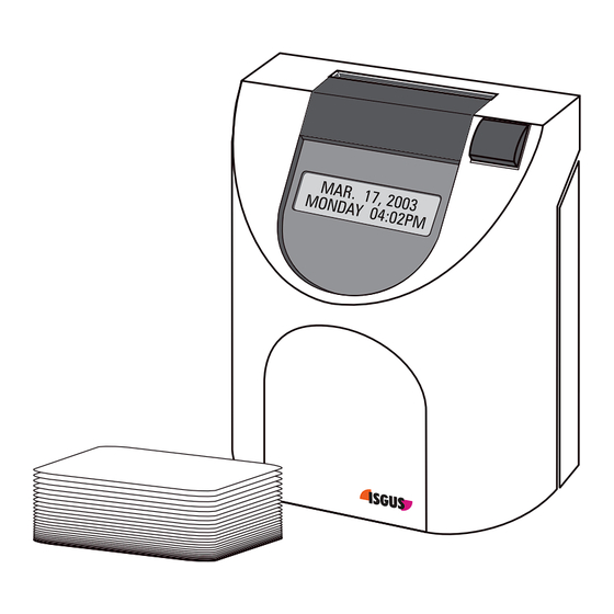
Page 18: Recorder Construction
Recorder Construction Fig. 1: Total view Display with day, date and time Card receiver Function key Removable front cover Rear cover 2-4 Features Chapter 2... -
Page 19: Time Recorder Identification
Time Recorder Identification • Electrical rating plate • Program data The name-plate is fixed on the bottom side of the cover. The serial number is attached to the inside bottom of the unit. Electrical data Type of recorder The label with the program data (1) can be found on the operating system PROM of the CPU. - Page 20 2-6 Features Chapter 2...
- Page 21 Chapter 3 Installation Contents................3-2 Selecting a Location ............3-3 General Conditions..........3-3 Specific Conditions for the Time Recorder..3-3 Time Recorder Installation ..........3-4 Installation for Table Operation....... 3-4 Wall Mounting ............3-5 Open the Recorder..........3-6 Close the Recorder ..........3-7 Remove the Metal Back Plate ......
-
Page 22: Contents
Set of accessories for table operation (4 rubber feet, 3 cover caps) Hint Time cards are not included with your time recorder and must be ordered separately. Please contact your local dealer or e-mail us sales@ca.isgus.com sales@isgus.com 3-2 Installation Chapter 3... -
Page 23: Selecting A Location
Selecting a Location Warning! Proper installation of the time recorder is the responsibility of the owner. All work must only be carried out by qualified personnel. The installation must comply with the requirements of the authorities having jurisdiction and all applicable safety codes and regulations that govern the installation of electrical appliances. -
Page 24: Time Recorder Installation
Time Recorder Installation Basically the PERFECT recorder is designed for table operation. No further settings are required for this type of application. Please see the instructions in the following section ”Installation for table operation”. If you have to connect additional functions such as signal operation, master clock operation or standby operation refer to the end of section "Wall mounting". -
Page 25: Wall Mounting
Select an easily accessible and vibration-free place of installation. The recorder may only be placed on a stable, slip-resistant surface. For the stability of the time recorder use the rubber feet included in the set of accessories. For this purpose clip them on by following the arrow-head indications. Also use the 3 cover caps for the metal back plate in order to seal the cable leadings. -
Page 26: Open The Recorder
Open the Recorder Insert the key into the slot on the under side of the time recorder. Press the key into the slot until the locking latch releases the front case cover. Fig. 6: Unlock the recorder Swing out the front case cover with the time recorder tilted away from you (step 1) until it can be lifted up and off the time recorder (step 2). -
Page 27: Close The Recorder
Close the Recorder Align and insert on an angle the two tabs at the top of the rear case cover into the corresponding two slots at the top of the front case cover. Swing the front case cover downwards until it meets the bottom of the rear case cover. -
Page 28: Wall Mounting
Wall Mounting The location of the mounting holes can be traced from the metal back plate of the time recorder. The metal back plate can be plugged in with the plastic housing. See previous section. The installation dimensions mentioned in this manual are recommendations which have to be adjusted for local conditions. - Page 29 Check the connection of the power cord to the screw-type terminal strip of the CPU. black black Attention The power cord must be connected to the PC board terminals that are electrically compatible with the supply voltage of the electrical outlet that the power cord is plugged into.
-
Page 30: Connect Additional Functions
Connect Additional Functions Only connect additional functions when they are required. Additional functions: − Signal operation − Master clock operation (payable option) − Slave clock operation (payable option) − Standby operation (payable option) All additional functions can be used for both types of installation, i.e. table or wall mounted version. - Page 31 Connect wiring for audible signal circuit control. → only if required. → low power signal output: 15V DC , 50 mA Attention This connection is polarity sensitive. Connect wiring for synchronized clock option → only if the recorder is equipped with the option module "MASTER CLOCK". →...
- Page 32 Connect impulse lines for slave clock connection. → Only if recorder is equipped with option module slave clock function/DCF" → unipolar and bipolar impulses, 12 V - 60 V, 2 - 10 mA. This connection is not polarity sensitive. The Installation is now finished. To program the time recorder see chapter 4 "Getting Started".
- Page 33 Chapter 4 Getting Started Preparations ..............4-3 Open the Recorder..........4-3 Powering Up The Time Recorder....... 4-3 Powering Down the Time Recorder....4-4 Programming Panel ............4-5 Date / Time ................. 4-7 Setting the Time only.......... 4-9 Set Time of Slave Clocks (optional) ....4-10 Programming..............
- Page 34 continued Fixed Break (Non Accumulation Times ....4-47 Change or Delete Values for Fixed Break (no accumulation) Time Ranges ......4-52 Red Print (Ribbon Color Change) ......4-53 Change or Delete Values for Red Print / Ribbon Color Changes........4-57 Overtime..............
-
Page 35: Preparations
Preparations Follow the instructions in this chapter and keep in the order the topics are presented. Basic procedure and overview: 1. Open the recorder 2. Switch on recorder 3. Check date and time, and reset if necessary 4. Program the recorder 5. -
Page 36: Powering Down The Time Recorder
Proceeding: Make sure that the switch on the CPU board is in the off position (O). Connect the time recorder’s power supply to the time recorder and then plug the power supply into the closest AC power outlet. Switch the power switch to position "1" (on). →... -
Page 37: Programming Panel
Programming Panel For obvious security reasons, the time recorder’s programming panel is locked under the front case cover and is not accessible to unauthorized users. To access the panel, a user must have a key to unlock and remove the front cover. Fig. - Page 38 Key S 〈Skip〉 → In the programming mode this key serves to sequentially skip from the current programming field to the next field. However, for the "S“ key to perform this function, the user must have programmed all values in the current field. →...
-
Page 39: Date / Time
Date / Time The recorder is provided with a battery-buffered quartz clock with power reserve. The lithium battery stores the correct time for years in case of power failure. Setting of date and time is usually necessary only during commissioning of the recorder. - Page 40 = Enter the desired minutes Range of values: 00 - 59 Note: By keeping this key pressed the value is scrolled. = Confirm setting. Recorder changes to date input. Date entry Entry format: DD MM YY The steps for setting the date are divided into day, month, year.
-
Page 41: Setting The Time Only
= Confirm the selection, setting routine is completed. The recorder changes to operating display and shows the current date and time. Hint: If the "Master Clock" option is enabled in the function programming, the time recorder will immediately begin to transmit minute impulses to connected slave clocks. -
Page 42: Set Time Of Slave Clocks (Optional)
• The "Slave Clock“ hardware and software options have been installed in those time recorders designated as slave clocks. • A 12“ diameter, 12 volt ISGUS system wall clock has been installed in those locations (locker rooms, offices etc.) designated to be slave clocks. - Page 43 Slave clock synchronization with unipolar activation = Call up the set time and date routine. ! Confirm time of master clock with "S" and date with "E" ! If it is necessary to change time and/or date of master clock, see previous instructions "...
- Page 44 ! After having confirmed the year with "E" the recorder changes to slave clock synchronization. Set slave clocks manually to the same time Hint: This display only appears when the setting "Reverse Pola" has been selected in the parameter "Master Clock". = Transmit single impulses to the slave clocks.
-
Page 45: Programming
Extreme caution is advised. It is recommended to replace the factory-set initial PIN code with your own individual number. However, if you forget your unique PIN code, you will have to return the time recorder to ISGUS for reprogramming. Chapter 4 Getting Started 4-13... -
Page 46: Calling Up The Programming Routine For The Main Programming Menu
Calling up the Programming Routine for the Main Programming Menu To call up the programming routine for the main programming menu, the front cover of the recorder must be removed. If the recorder is switched off, you must switch it on with the mains switch. -
Page 47: Print Format
Print Format Print formats determine how and where "IN" punches, "OUT" punches, and various combinations of hour totals are printed on the time card. With the aid of this function you can select in addition the minutes printing format. Card example Format Column Column... - Page 48 Hint With the unit you can use one of 2 possible standard card types. The cards differ by their card width. The print formats 1 to 3 and 9 to 12 are not suited for the small card type. Formats 1-8 In columns 4 and 8 the clocking difference between IN and OUT punchings is determined and printed.
- Page 49 Format 13 The normal time is printed out in column 4 and the overtime is printed out in column 5. The total from column 4 and column 5 produces the presence time. Column 6 shows the cumulative total of normal time. Column 7 shows the cumulative total of overtime.
- Page 50 = Select range of validity for minute printing format. Range of values: Totals, Punches + Totals = Confirm selection and continue with next parameter. Hint If 10THS or 100THS is selected as the format for the minutes printout, a * is displayed to the right of the current time on the display, e.g.
-
Page 51: Punch Rounding
Punch Rounding The PERFECT has the ability to round "In“ and "Out“ punches either forwards or backwards depending on company defined qualification periods. The first step in programming punch rounding is to establish the time intervals that the time recorder will divide work hours into. We call these "time accounting units“. The available time accounting units are: 2, 3, 5, 6, 10, 12, 15, 20 and 30 minutes. - Page 52 not rounded original punching time is printed Date Total (printed) (rounded and (printed) (rounded and not printed) not printed) 03.12.00 7:51 7:45 AM 11:50 AM 11:45 4.00 04.12.00 7:52 8:00 AM 11:51 PM 12:00 8.00 rounded punching time is printed Date Total (not printed)
- Page 53 = Confirm selection. = Set rounding qualification for IN punching. Range of values: 00 - 29 min. Hint: By keeping this key pressed the value is scrolled. = Confirm selection. = Set rounding qualification for OUT punching. Range of values: 0 - 29 min. Note: By keeping this key pressed the value is scrolled.
-
Page 54: Totals Rounding
Totals Rounding The recorder has a rounding function for results. The intervals that the time recorder will divide work hours into are called "time accounting units". The time accounting units (rounding intervals) can be selected in steps of: 2, 3, 5, 6, 10, 12, 15, 20 and 30 minutes. In addition a rounding qualification can be created. - Page 55 Example 2 Rounding differences (= include sub-totals) Date Difference Difference Total (not printed) (rounded and (printed) printed) 01.12.00 AM 7:00 AM 11:08 4.08 4.00 4.00 01.12.00 PM 1:00 PM 5:16 4.16 4.15 8.15 02.12.00 AM 7:00 AM 11:15 4.15 4.15 12.30 02.12.00 PM 1:00 PM...
- Page 56 = Set rounding qualification. Range of values: 00 -14 min. Hint: By keeping this key pressed the value is scrolled. = Confirm selection. Recorder changes to input level. = Select function. Selection: - EXCLUDE SUB.TOT - INCLUDE SUB.TOT = Confirm selection and return to menu level.
-
Page 57: In Punch Revisions
IN Punch Revisions It is possible to set 4 time ranges per weekday within which the first IN punch of the employees is rounded. The definition of such revision time ranges makes it possible to - round the first IN punch of an employee to the start of working time e.g. - Page 58 not rounded original punching time is printed Date Total (printed) (rounded and not printed) 25.11.02 AM 7:30 AM 8:00 PM 12:00 4.00 26.11.02 AM 8:01 AM 8:00 PM 12:00 8.00 27.11.02 AM 8:06 AM 8:00 PM 12:00 12.00 28.11.02 AM 8:07 AM 8:07 PM 12:00 15:53...
- Page 59 Proceeding = Activate the function Switch to the next parameter with "S". = Confirm setting Recorder changes to the next input level. = Select the day of the week to program the IN punch revision schedule. Range of values: MO to SU Example: MO;...
- Page 60 Hint: If the 12 hour time mode is selected, a change from AM to PM is to be achieved by scrolling the hour value. Possible time indications for the following day are automatically marked with "+" in the 12 hours mode as well as in the 24 hours mode.
- Page 61 = Select the "copy to" day(or days) Hint: With this function you can copy the defined values directly to consecutive weekdays. All you do is select the last consecutive weekday instead of just the next weekday, e.g. Friday instead of Tuesday.
- Page 62 = Confirm selection and return to menu level. = Continue with next parameter. Hint: Use "E" to return to the input level. Hint If, in addition, the PUNCH ROUNDING function is activated, the recorder ignores the settings of the PUNCH ROUNDING function during an IN punch revision time range.
-
Page 63: Change Or Delete Values For Schedules With In Punch Revisions
Change or Delete Values for schedules with IN Punch Revisions The IN Punch Revision schedules can be modified at any time. Use the copy function in order to change or delete several days at a time. Procedure: Call-up the programming routine. ("R"... -
Page 64: Out Punch Revisions
OUT Punch Revisions It is possible to set 4 time ranges per weekday within which the OUT punch of the employees is rounded. The definition of such time ranges makes it possible to - round the OUT punch of an employee to the end of working time e.g. - Page 65 not rounded original punching time is printed Date Total (printed) (rounded and not printed) 25.11.02 PM 01:00 PM 04:44 PM 04:44 3.44 26.11.02 PM 01:00 PM 04:45 PM 05:00 7.44 27.11.02 PM 01:00 PM 05:10 PM 05:00 11.44 28.11.02 PM 01:00 PM 05:30 PM 05:00 15.44 rounded punching time is printed...
- Page 66 Proceeding = Activate the function Switch to the next parameter with "S". = Confirm setting Recorder changes to the next input level. = Select the day of the week to program the OUT punch revision schedule. Range of values: MO to SU Example: MO;...
- Page 67 Hint: If the 12 hour time mode is selected, a change from AM to PM is to be achieved by scrolling the hour value. Possible time indications for the following day are automatically marked with "+" in the 12 hours mode as well as in the 24 hours mode.
- Page 68 = Select the "copy to" day (or days) Hint: With this function you can copy the defined values directly to consecutive weekdays. All you do is select the last consecutive weekday instead of just the next weekday, e.g. Friday instead of Tuesday.
- Page 69 = Confirm selection and return to menu level. = Continue with next parameter. Hint: Use "E" to return to the input level. Hint If, in addition, the PUNCH ROUNDING function is activated, the recorder ignores the settings of the PUNCH ROUNDING function during an OUT punch revision time range.
-
Page 70: Change Or Delete Values For Schedules With Out Punch Revisions
Change or Delete Values for schedules with OUT Punch Revisions The OUT Punch Revision schedules can be modified at any time. Use the copy function in order to change or delete several days at a time. Procedure: Call-up the programming routine. ("R"... -
Page 71: Automatic Break
Automatic Break By enabling this function it is possible to control the calculation of the total of daily paid and unpaid breaks. Up to 4 break rules can be defined in the unit. The rules are not linked together. With each punching pair the fulfilling of the rule conditions is checked. - Page 72 Hint For the determination, which break rule is to be calculated, 2 conditions must be fulfilled - the Elapsed Time is reached or exceeded - the Min. Worked is reached or exceeded Example 1: Rule 1 Rule 2 Elapsed Time 4.00 7.00 0.10...
- Page 73 Example 2: Rule 1 Rule 2 Rule 3 Elapsed Time 4.00 6.00 9.00 Min. Deduct 0.15 0.30 0.45 Min. Worked 3.30 5.30 8.30 Paid Break 0.05 0.10 0.20 Conditions for the determination Rule Calculation Interval Card of the break rule Elapsed Time Total Total...
- Page 74 Example 3: Rule 1 Rule 2 Elapsed Time 4.00 7.00 Min. Deduct 0.10 0.20 Min. Worked 3.00 6.00 Paid Break 0.10 0.20 Fixed Break (Non accumulation) schedule = from PM 12:00 to PM 12:30 Conditions for the determination Rule Calculation Interval Card of the break rule...
- Page 75 Example 4: Rule 1 Rule 2 Rule 3 Elapsed Time 4.00 6.00 9.00 Min. Deduct 0.15 0.30 0.45 Min. Worked 3.30 5.30 8.30 0.05 0.10 0.20 Paid Break Fixed Break (Non accumulation) schedule = from PM 12:00 to PM 12:30 Conditions for the determination Rule Calculation...
- Page 76 Proceeding = Activate the function. Switch to the next parameter with "S". = Confirm setting. Recorder changes to input level with the qualification values of the first break rule. 1. setting = Elapsed Time 2. setting = Min. Deduct 3. setting = Min. Worked 4.
- Page 77 = Set Min. Deduct of first break rule. Format: HH.MM 1st input field = hours 2nd input field = minutes = Set desired hour Range of values: 00 - 18 = Confirm setting = Enter the desired minutes Range of values: 00 - 59 = Confirm setting Recorder changes to next menu level...
- Page 78 = Set Paid Break of first break rule. Format: HH.MM 1st input field = hours 2nd input field = minutes = Set desired hour Range of values: 00 - 18 = Confirm setting = Enter the desired minutes Range of values: 00 - 59 = Confirm setting Recorder changes to next menu level...
-
Page 79: Fixed Break
Fixed Break (Non Accumulation Times It is possible to set 4 time ranges per weekday within which no time accumulation is made. The definition of such time ranges makes it possible to: - program fixed breaks which are not added to the presence time and must not be punched by the employees - limit the working time to be calculated Example A: Fixed break... - Page 80 Hint In order to use this function also for punch pairs, where the OUT punch is made after the date change, the fixed break (non accumulation) schedule must also be defined beyond date change. In the input routine possible time settings for the following day are automatically marked with "+"...
- Page 81 = Select the day of the week to program the fixed break (no accumulation) time range. Range of values: MO to SU Example: MO; It is also possible to start on any other weekday. Note: By keeping this key pressed the value is scrolled. = Confirm selection.
- Page 82 Repeat this procedure for further fixed break (no accumulation) time ranges for this weekday. = Return to the previous input level when you have entered all fixed break (no accumulation) time ranges for this weekday. Select a new day if fixed break (no accumulation) time ranges differ from the already defined weekday.
- Page 83 Repeat the copying process if further fixed break (no accumulation) time ranges shall be copied to other weekdays. = Return to the previous input level, when you have copied all fixed break (no accumulation) time ranges. = Continue with next parameter. Hint: Use "E"...
-
Page 84: Change Or Delete Values For Fixed Break (No Accumulation) Time Ranges
Change or Delete Values for Fixed Break (no accumulation) Time Ranges The fixed break (no accumulation) schedules can be modified at any time. Use the copy function in order to change or delete several days at a time. Procedure: Call-up the programming routine. ("R"... -
Page 85: Red Print (Ribbon Color Change)
Red Print (Ribbon Color Change) To highlight exceptional punches on a time card, the time recorder has the capability to print in two different colors (black and red). It can be programmed to change color up to 8 times a day. The menu item "Red Print"... - Page 86 Proceeding = Activate the function Switch to the next parameter with "S". = Confirm setting. Recorder changes to next input level. = Select the day of the week to program the ribbon color changes Value range: MO to SU Example: MO; It is also possible to start on any other weekday.
- Page 87 Hint: If the 12 hour time mode is selected, a change from AM to PM is to be achieved by scrolling the hour value. = 2. Confirm input field. The values are stored and the display is emptied, the first input field flashes again.
- Page 88 = Select the "copy to“ day (or days). Hint: With this function you can copy the defined values directly to consecutive weekdays. All you do is select the last consecutive weekday instead of just the next weekday, e.g. Friday instead of Tuesday.
-
Page 89: Change Or Delete Values For Red Print / Ribbon Color Changes
Change or Delete Values for Red Print / Ribbon Color Changes The ribbon color change program can be modified or deleted at any time. Use the copy function in order to modify or delete several days at a time. Procedure: Call-up the programming routine. -
Page 90: Overtime
Overtime By activating the function "Overtime" it is possible to calculate overtime. If function "Overtime 2" is additionally activated it is possible to accumulate overtime in 2 accounts. Hint If only overtime account 2 is enabled, it is not possible to calculate overtime. - Page 91 Definitions and qualification values for the following examples with only one enabled overtime account: Print format = 9 or 10 Daily qualification = 8 hours Saturday qualification = 4 hours Sunday qualification = 0 hours Public holiday qualification = 0 hours Weekly qualification = 40 hours Reset weekly overtime...
- Page 92 Example 2 Weekly qualification with normal time + overtime Employee works as Diff. Diff. Total normal Total follows normal time overtime time overtime Monday = 10 h Tuesday = 9 h Wednesday = 8 h Thursday = 10 h Friday = 9 h Saturday = 6 h...
- Page 93 = Confirm setting Recorder changes to the input level of the qualification parameter. 1st setting = Daily Qualification 2nd setting = Saturday Qualification 3rd setting = Sunday Qualification 4th setting = Public Holiday Qualification 5th setting = Weekly Qualification 6th setting = Reset Weekly Overtime qualification 7th setting = WK...
- Page 94 Set weekly qualification Format: HH.MM 1st input field = hours 2nd input field = minutes = Set desired hour Range of values: 00 - 99 = Confirm setting = Enter the desired minutes Range of values: 00 - 59 = Confirm setting Recorder changes to next input level.
-
Page 95: Option Menu
Option Menu Key "E" = Entering of the Option Menu Key "S" = End of Programming When entering this menu further items are available Calling up the Programming Routine for the Options Menu To call up the programming routine for the option menu, the front cover of the recorder must be removed. - Page 96 Hint The "CHANGE PINCODE" field appears every time you enter the programming mode of the option menu. Enter the new PIN-code in the same manner you enter the existing PIN code. Warning! Do not use the "E" key when this prompt appears otherwise you enter a PIN code with the numbers 0000.
-
Page 97: Daylight Savings Time
Daylight Savings Time Daylight savings time changes can be programmed to occur automatically. You can select either a perpetual automatic change over based on fixed rules of your geographic area or you may select to program the time change every year based on one time dates. - Page 98 = Select switch-over mode. 01 = perpetual change according to CET last Sunday in March, 02:00 >> 03:00; last Sunday in October, 03:00 >> 02:00; 02 = perpetual change according to CET last Sunday in March, 02:00 >> 03:00; 4. Sunday in October, 03:00 >>...
- Page 99 ! If you have selected codes "01" to "07", move to the next field, "Deleting Cards“ by pressing the "S“ key ! If you have selected code "99", continue on with the following sequence. Recorder changes to next input level. First enter the spring change over values.
- Page 100 Proceed as described for summer switch-over. Order: Day, month, time = Set the value. = Confirm settings. Hint: Do not use the "E" key for confirmation after the minute value input. = Quit Daylight Savings Time change-over and return to menu level.
-
Page 101: Deleting Cards
Deleting Cards This function enables the manual deletion of any time card from the time recorder’s memory using the black function key on the top right hand side of the front case cover. The programming of this field does not in itself delete any cards from the system, it only enables their deletion by the black key, when the time recorder is in normal operating mode. -
Page 102: Maximum Presence
Maximum Presence The time recorder uses the "Max on“ function to determine if an employee has forgotten to punch out. If the elapsed time between a pair of punches exceeds the Max on time parameter, the time recorder assumes that the employee forgot to punch out and does not credit the time to the employee’s totals. - Page 103 Proceeding = Deactivate the function. Switch to the next parameter with "S". = Confirm setting. Recorder changes to next input level. = Select hour value. Factory setting: 12 h Hint: First enter tenth digit with "R" and confirm with "E", then set the units digit.
-
Page 104: Date Format
Date Format The date print format is available in two versions. Style 1: Style 2: W MM / DD / YY W DD / MM / YY Year Year Month Month Weekday abbreviation Weekday abbreviation → style 1 Factory setting: Proceeding = Select format. -
Page 105: Day End
Day End In order to credit worked hours after midnight to the previous day, the unit offers 2 functions to shift the day end beyond midnight. - function "DAY END" - function "DAY EXTEND" (see following section "DAY EXTEND") With the function "DAY END" the day end is shifted to a fixed time. Example A: DAY END (DE) not activated Value for DAY END = AM 12:00 Mo 09:00 PM... - Page 106 Proceeding Enter time Format: HH:MM = Set desired hour Range of values: 00 - 24 Hint: If the 12 hour time mode is selected, a change from AM to PM is to be achieved by scrolling the hour value. = Confirm setting. = Enter the desired minutes Range of values: 00 - 59 Hint: By keeping this key...
-
Page 107: Day Extend
Day Extend In order to credit worked hours after midnight to the previous day, the unit offers 2 functions to shift the day end beyond midnight. - function "DAY EXTEND" - function "DAY END" (see previous section "DAY END") With the function "DAY EXTEND" the day end is shifted by a programmable time value to the next day, depending on the last IN punching of the employee. - Page 108 → Function activated Factory setting: DAY EXTEND = 12 hours Proceeding Enter time Format: HH.MM = Set desired hour Range of values: 00 - 18 = Confirm setting. = Enter the desired minutes Range of values: 00 - 59 Hint: By keeping this key pressed the value is scrolled.
-
Page 109: Overtime 2
Overtime 2 By activating the function "Overtime" it is possible to calculate overtime. If function "Overtime 2" is additionally activated it is possible to accumulate overtime in 2 accounts. Hint If only overtime account 2 is enabled, it is not possible to calculate overtime. - Page 110 In Example 1, normal working time and overtime form Monday to Thursday are calculated according to the daily qualification the employee has reached. On Thursday the employee reaches the weekly qualification 1 by his normal working time. All further times are calculated as overtime. On Saturday the employee reaches the weekly qualification 2 by his normal working time.
- Page 111 In Example 2, normal working time and overtime form Monday to Tuesday are calculated according to the daily qualification the employee has reached. On Wednesday the employee reaches the weekly qualification 1 by his normal working time and overtime 1 + 2. All further times are calculated as overtime. On Thursday the employee reaches the weekly qualification 2 by his normal working time and overtime 1 + 2.
- Page 112 Set daily qualification Format: HH.MM 1st input field = hours 2nd input field = minutes = Set desired hour Range of values: 00 - 24 = Confirm setting = Enter the desired minutes Range of values: 00 - 59 = Confirm setting Recorder changes to next qualification parameter Hint: By keeping this key...
- Page 113 = Select weekday when the weekly qualification is to begin again. Range of values: MO to SU, DS (disable) = Confirm setting. Recorder changes to next input level. = Definition of the weekly qualification Range of values: RT / RT + OT = Continue with next parameter.
-
Page 114: Public Holidays
Public Holidays Up to 16 public holidays can be entered in PERFECT 2040 which are valid for all persons clocking at the recorder. Entering public holidays enables the recorder to calculate overtime for such days according to the special public holiday qualification. The precondition for this is, however, that the overtime function with public holiday qualification is activated. - Page 115 = Confirm setting Recorder changes to date input. Date entry Format: MM DD The display and thus the input is divided into day and month. First setting is the day Range of values: 01 - 31 = Enter the desired day. = Confirm setting.
-
Page 116: Deleting Public Holidays
Deleting Public Holidays Public holidays can be deleted subsequently at any time. Procedure: Call-up the programming routine. ("R" key) Select the "Public holiday" menu ("S" key) Call up the date to be changed. (Click through with "E" key) Deleting public holidays ("R"... -
Page 117: Card Initialization
Card Initialization Your ISGUS time cards are bar-coded with consecutive numbers, from 0 to 999,999. It is through this bar-code that the time recorder identifies which time card it is printing on and how to calculate the time worked for that card. - Page 118 = Confirm setting. Recorder changes to next input level. 1. setting = card no. from 2. setting = card no. to = Set the card number range, here card no. "from". Hint: Enter the digits subsequently with "R" and confirm each with "E". = Set the card number range, here card no.
-
Page 119: Duplicate Punch
Duplicate Punch The function "Duplicate punch " serves to avoid accidental double punching with the same card within a short interval, i.e. unintentionally inserting the card a second time. If this feature is enabled, the interval after which the time recorder will accept the next punch must be programmed. -
Page 120: Reproducing Card
Reproducing Card The feature "Reproducing card" does not need to be programmed. It is a standard utility that allows you to transfer the current card total of a lost or damaged card to a new time card. For information on how to use this feature, Please refer to chapter 5 "Operation", section "Card Management / Card Organization". -
Page 121: Lock Out
Lock Out It is possible to set 4 time ranges per weekday within which the employees are not authorized to punch. Example: Lock out schedule on Monday Start AM 7:00 End AM 8:00 If an employee attempts to make an IN punching between 7:00 and 7:59 hours, the recorder rejects the card and displays the following reason for rejection: "LOCK OUT"... - Page 122 = Select the day of the week to program the lock out time range Range of values: MO to SU Example: MO; It is also possible to start on any other weekday. Hint: By keeping this key pressed the value is scrolled. = Confirm selection.
- Page 123 = Return to the previous input level when you have entered all lock out time ranges for this weekday. = Select a new day if the lock out time ranges differ from the already defined weekday. Proceed as described previously. = Switch over to the copying function.
- Page 124 = Return to the previous input level, when all lock out time ranges are copied. = Continue with next parameter. Hint: Use "E" to return to the input level. 4-92 Getting Started Chapter 4...
-
Page 125: Change Or Delete Values For Lock Out Schedules
Change or Delete Values for Lock Out Schedules The ranges set for lock outs can be subsequently changed or deleted at any time. Use the copying function in order to change or delete several weekdays at a time. Procedure: Call-up the programming routine. ("R"... -
Page 126: Signal Operation
Signal Operation By programming the time recorder’s signal circuit, an external signaling device, such as a horn or a bell, can control the signaling of coffee breaks or work start and stop times. Programming the signal circuit is very similar to programming ribbon color changes. Up to 32 signals for each day of the week can be programmed and the user must define day, time and duration of each external signal event. - Page 127 Proceeding = Activate the function Quit programming mode with key "S". = Confirm setting. Recorder changes to next input level. = Select the day on which the signal times shall apply. Value range: MO to SU Example: MO; It is also possible to start on any other weekday.
- Page 128 Hint: The AM/PM setting is linked with the hour setting. In other words, to switch from AM to PM scroll the hour value. = Confirm 2. input field. The values are stored and the display is emptied, the first input field flashes again. Repeat this procedure for further signal switching times for this weekday.
- Page 129 = Select the "copy to“ day Hint: With this function you can also copy the defined values directly to several weekdays. Now, select the last weekday of the range instead of the following weekday, e.g. Friday instead of Tuesday. = Confirm 2. input field. Repeat the copy process if other signal schedules are to be copied to other days.
-
Page 130: Change Or Delete Values For Signal Operation
Change or Delete Values for Signal Operation The signal program entered during start-up can be modified or deleted at any time. Use the copy function in order to modify or delete several days at a time. Procedure: Call-up the programming routine. ("R"... -
Page 131: Slave Clock Function
Slave clock function The 2040 recorder can be used as a slave clock. The synchronization of time is effected through a master clock, e.g. a further PERFECT recorder with enabled master clock function. For this function the slave clock additional board (payable option) has to be integrated in the recorder. -
Page 132: Master Clock Function
Master Clock Function The PERFECT time recorder can be used as a master clock to control and synchronize other PERFECT time recorders and ISGUS slave wall clocks. For this feature to be functional, the master clock hardware module (payable option) must be installed on the time recorder’s CPU board and all slave clocks must be... -
Page 133: Synchronize The Slave Clocks
= Confirm entry and return to menu level. = Continue with next value. Hint: Use "E" to return to the input level. Synchronize the Slave Clocks Only after finishing the complete programming of the time recorder, should you then proceed to synchronize the slave clocks. First, make sure that all reverse polarity type slave clocks are set to the same polarity. - Page 134 If you have any questions, please contact your local dealer where you have purchased the time recorder or e-mail us at: support@ca.isgus.com techsupport@isgus.com 4-102 Getting Started Chapter 4...
-
Page 135: Card Validity Duration
Card Validity Duration A validity duration can be defined for the cards saved in the recorder. At the end of this period the card is rendered invalid and will be deleted automatically from the recorder. The period in days since the last punch is used as deleting criterion. If the recorder does not register any further punch at the end of the validity duration period, the card will be deleted automatically. - Page 136 = Confirm entry and return to menu level. = Continue with next value. Hint: Use "E" to return to the input level. 4-104 Getting Started Chapter 4...
-
Page 137: Quit Programming Mode
Quit Programming Mode After quitting the menu item "Master Clock" with the "S" key, the programming routine of the option menu is terminated. The recorder automatically carries out an initialization routine during which it sets up the new programmed values. After having completed the initialization routine, the current date and time are displayed. -
Page 138: Service Call
Service Call It is possible to program a date giving you a hint, that you should consult your sales and service partner to arrange an appointment for the maintenance of the unit. Proceeding = Activate the function by pressing simultaneously key "R"... - Page 139 = Confirm setting. Recorder changes to year. = Set desired year. Value range: 00 - 99 Note: By keeping this key pressed the next value is scrolled. = Confirm the selection, setting routine is completed. The recorder changes to operating display and shows the current date and time.
-
Page 140: Print Out Of Program Settings
Print out of Program Settings The recorder offers two possibilities to print out all customer specific program settings: - the individual menu items, successively during the programming process - complete, after the programming by selection of menu "Protocol Print" For a complete protocol print out 6 time cards are required. Hint In order not to initiate an IN or OUT punch while printing the protocol print out of the program settings, the back of a card... - Page 141 Procedure for protocol print out after programming: = Activate the function by pressing simultaneously key "E" and "S" Insert blank card. Card is retracted and complete protocol print is started. Using "S" for ending the printing procedure. Remove card when programming has been finished.
-
Page 142: Getting Started
Extract of a complete protocol print out Page 1 Page 2 Page 3 OVERTIME 2.35 05/18/05 PRINT FORMAT 2.35 05/18/05 AUTOMATIC BREAK 2.35 05/18/05 23.59 23.59 23.59 04.00 07.00 23.59 40.00 01 01 00.10 00.20 03.00 06.00 DAYLIGHT SAVINGS 00.10 00.20 GLOBAL ROUNDING 00.00 00.00 15 08 08... - Page 143 Chapter 5 Operation Punching at the Recorder..........5-2 Card Structure / Card Print ........5-2 Requirements for Trouble Free Time Recording IN / OUT Punches .............. 5-5 Double Punch Disabling ........5-6 Forgotten OUT Punches (Max On)..... 5-7 Card Full............. 5-8 Card Management / Card Organization ......
-
Page 144: Punching At The Recorder
Punching at the Recorder The time recorder is shipped from the factory with default program settings that make it ready for operation. The user needs only to set time and date for the specific time zone. However if you do not program the time recorder to your individual requirements, you will not benefit from many of its outstanding features. - Page 145 It is only possible to print on one side of the time card. The back side of the card bears the bar code which enables the time recorder to identify the individual time card being inserted. The front side of the card is divided into various fields. Card header: Contains individual fields and entries, such as card user, company, accounting period, etc.
-
Page 146: Requirements For Trouble Free Time Recording
Total: Column Format: HH.MM This is the first of two time card “Total” columns provided for each pair of IN/OUT punches. If used, it will display the elapsed time between the two immediately preceding IN/OUT punches. If not used, the column will be blank. Column use is determined when selecting one of eight print formats during time recorder setup. -
Page 147: In / Out Punches
IN / OUT Punches Using the PERFECT 2040 time recorder is very easy. An employee inserts the time card into the card receiver throat at the top of the machine. A motorized device pulls the card down into the time recorder. Automatically, the time recorder prints the time in the correct position on the time card and returns the time card up to the top of the machine. -
Page 148: Double Punch Disabling
Double Punch Disabling The time recorder is provided with the capability to inhibit double punching of time cards. In the “Duplicate Punch” software feature, the user specifies the minimum number of minutes that must elapse after a time punch (either IN or OUT) before the time recorder will allow a subsequent punch on the same time card. -
Page 149: Forgotten Out Punches (Max On)
Forgotten OUT Punches (Maximum Presence) The time recorder can be programmed to ignore the elapsed time between a pair of IN/OUT punches if the elapsed time exceeds a user defined number of hours. This is done to prevent inflated time card totals caused by employees forgetting to punch out. -
Page 150: Card Full
Card Full The time recorder automatically senses when the time card is full. Up to 31 lines of punches can be made on each time card. Each row can accommodate either one or two pairs of IN/OUT punches depending on which print format is selected by the user. -
Page 151: Card Management / Card Organization
Card Management / Card Organization Your PERFECT offers several time card management options. Which options you select to use depends on the requirements, policies and practices of your company. The following sections are intended to offer you an overview of the management of time cards as it applies to the PERFECT 2040. -
Page 152: Card Management Options
time cards due to employment status. After deleting the employee time card, the supervisor will then disable the feature. If the time recorder is used for non-time-and-attendance applications such as job costing and parking lot operation, this application is also used when a job is finished or when the car leaves the parking lot. - Page 153 oldest time card totals are simply overwritten by the new time cards. The oldest saved card is the card with which the oldest bookings have been effected prior to the last bookings of the other existing cards. Advantage: Quick commissioning and quick start of the recorder with no need for time card number maintenance .
- Page 154 Advantage: This operating mode serves best to guarantee the control of card management. The memory capacity will never be exhausted and the user controls the exact number of cards saved in the time recorder’s memory. Disadvantage: Card deleting has to be carried out manually and is time consuming.
-
Page 155: Deleting Cards Without Carryover
Deleting cards without Carryover The unit offers 3 functions to delete time cards manually from the time recorder: - Deleting cards without Carryover - Deleting cards with Carryover of Totals - Deleting cards with Carryover of Weekly Qualification Hours and Deletion of Totals For this applications, please refer to section "Card Management”. -
Page 156: Deleting Cards With Carryover Of Totals
Deleting cards with Carryover of Totals The unit offers 3 functions to delete time cards manually from the time recorder: - Deleting cards without Carryover - Deleting cards with Carryover of Totals - Deleting cards with Carryover of Weekly Qualification Hours and Deletion of Totals For this applications, please refer to section "Card Management”. - Page 157 On the bottom line of the time card, the following note is printed: CARD DELETED WITH CARRYOVER This serves to inform the user that the time card and its totals are no longer saved in the time recorder 4. Remove the card. The following display message appears: 5.
-
Page 158: Deleting Cards With Carryover Of Weekly Qualification Hours And Deletion Of Totals
Deleting cards with Carryover of Weekly Qualification Hours and Deletion of Totals The unit offers 3 functions to delete time cards manually from the time recorder: - Deleting cards without Carryover - Deleting cards with Carryover of Totals - Deleting cards with Carryover of Weekly Qualification Hours and Deletion of Totals For these applications please refer to section "Card Management”. - Page 159 3. Press the function key again. The following display message appears: CARD DELET.WITH C.OVER WEEKQUAL 4. Insert the time card to be deleted. Hint: The function remains active for about 8 seconds. For safety reasons, if no card is inserted during this time, the display will revert to the date and time indicating a return to the normal operating mode.
- Page 160 The totalization of normal working time and overtime restarts with 0 on the new time card. 7. Remove the new card. 8. The following display message appears: CARD DELET.WITH C.OVER WEEKQUAL To delete further cards, repeat steps 4 to 7. The function remains active for about 8 seconds.
-
Page 161: Reproducing Time Card
Reproducing Time Card With the PERFECT 2040 you can delete time card totals from a lost or damaged time card and transfer them to a new undamaged time card. This software feature is only accessible in the password protected programming routine of the time recorder. - Page 162 Hint: The function or the display message remains active for about 5 seconds. If no card is inserted during this time the message will revert to the display prompt requesting you to enter the card number of the lost or damaged time card.
-
Page 163: Summary By Cards
Summary by Cards This feature provides a summary report of the hours totals for a defined range of time cards within the memory of the time recorder. Summary report creation is only intended for use by supervisors and therefore can only be accessed through the password protected programming routine. - Page 164 4. Select the report format. ("R" key) You can choose between output on the display or time card print. Confirm the selection with "E". → If display output is selected, continue with step 5. → If time card print is selected, continue with step 7. 5.
- Page 165 Attention! A maximum of 31 lines can be printed on an empty time card. For the printout of the summary, one line is required per card number. Depending on the report’s number range of the report , a corresponding number of blank time cards is required, e.g.
-
Page 166: Standby Operation
Standby operation An optional standby battery pack is available to maintain normal operation of the time recorder in the event of an AC power failure. If power does fail, the time recorder transfers automatically to the batteries without any intervention by the user. When AC power is restored, the time recorder automatically reverts to standard operation and recharges the batteries. - Page 167 Chapter 6 Trouble Shooting Error Messages ..............6-2 Change of Fuse for Signal Output ........6-3 Removing of the Battery Pack.......... 6-4 Adjustment of Card Sensor ..........6-5 Cleaning of the Card Sensor ..........6-6 Service Call................ 6-8 Chapter 6 Trouble Shooting 6-1...
-
Page 168: Error Messages
Error Messages Most hardware and software malfunctions are indicated by an error message on the display. If the problem cannot be solved, please contact your local dealer or e-mail us at: support@ca.isgus.com techsupport@isgus.com Display Cause Remedy P-Module, Error in resident Switch recorder off and on. -
Page 169: Change Of Fuse For Signal Output
Change of Fuse for Signal Output The low power signal output is protected by a replaceable fuse. This fuse only effects the signal output and is not relevant for the whole unit. The fuse in the external power supply is meant for the unit itself. Use only fuses with the same technical data. -
Page 170: Removing Of The Battery Pack
Removing of the Battery Pack The battery pack (payable option) maintains normal operation of the time recorder in the event of an power failure. The PERFECT 2040 is not equipped with battery pack ex factory. The clamp X5 of the PC-board is bridged by a z-diode (12 V / 1 W). Units with battery pack installed are not equipped with this bridge. -
Page 171: Adjustment Of Card Sensor
Adjustment of Card Sensor Due to elemental ageing and wearout it is possible that the reading quality of the card sensor is diminished in the course of time. An adjustment of the card sensor can re-increase the reading quality. The sensor adjustment has been executed when programming the time recorder in factory. -
Page 172: Cleaning Of The Card Sensor
Cleaning of the Card Sensor Because of electrostatic charging, dust depositions on electronic devices are possible in the course of time. The reason might be paper abrasion as a consequence of card insertion or the place of installation itself. The card sensor is one of the parts concerned. - Page 173 Mount the metal back plate. Close the time recorder. Fig. 16: Cleaning of card sensor We recommend maintenance and cleaning of the time recorder in certain intervals. For this purpose you can also make use of the function "Service call" , see chapter 4 "Getting Started"...
-
Page 174: Service Call
Service Call In order to keep the unit fully operational over the entire service life, regular maintenance is necessary. Depending on the degree of utilization and the place of installation, some components of the unit may be subject to wear out. These parts are exposed to natural wear and/or ageing and should be checked by trained service technicians at certain intervals. - Page 175 Chapter 7 Maintenance Ribbon Change..............7-2 Cleaning the Time Recorder..........7-3 PERFECT Info Display ............7-4 Service Call................ 7-4 Chapter 7 Maintenance 7-1...
-
Page 176: Ribbon Change
Hint The ribbon used in this time recorder is not a standard one. If you need to order more ribbons, please contact your local dealer or e-mail us at: sales@ca.isgus.com sales@isgus.com Procedure The recorder is switched on or off. Open the recorder and remove the front cover. -
Page 177: Cleaning The Time Recorder
Pull the ribbon cassette upwards. Warning! Be careful not to burn yourself when touching the printer head. Depending on print activity, the printer head may be very hot. Touching the printer head could cause burns. Insert a new ribbon cassette and push slightly down. Tighten the new ribbon by winding the red ribbon tightening knob in the direction indicated by the arrow on the cassette. -
Page 178: Perfect Info Display
PERFECT Info Display With this function it is possible to request the type and the program release of the recorder during normal operating mode. Procedure: Keep function key pressed for approx. 2 seconds. If no optional program functions are activated, the PERFECT info is displayed: →... -
Page 179: Technical Specifications
Appendix A Technical Specifications Appendix A Technical Specifications A-1... - Page 180 Technical Specifications Dimensions Height: 280 mm (11.02 inches) Width: 220 mm (8.67 inches) Depth: 195 mm (7.68 inches) Weight 3.2 kg 20 V AC +/- 10 % 50 - 60 Hz Supply voltage max. 800 mA Current consumption Power consumption max.
- Page 181 Appendix B Default Program Settings Appendix B Default Program Settings B-1...
- Page 182 Print Format Punch Rounding Totals Rounding In Punch Revisions Out Punch Revisions Automatic Break Fixed Break Red Print Overtime Option Menu Change PIN code Daylight Savings Time Deleting Cards B-2 Default Program Settings Appendix B...
- Page 183 Maximum presence Date format Day end Day extend Overtime 2 Public Holiday Card Initalization Duplicate Punch Reproducing card Summary by cards Lock out Signal Operation Master/slave clock function Card validity duration Appendix B Default Program Settings B-3...
- Page 184 B-4 Default Program Settings Appendix B...
- Page 185 Appendix C Program Settings Appendix C Program Settings C-1...
- Page 186 Before programming, you should create a written record of your time recorder’s program settings. This allows you to reference these settings while programming the time recorder and also allows you to refer to them at a later date without re-entering the unit’s programming mode.
- Page 187 OUT PUNCH REVISION DAY _____ FROM _____ TO __________ DISABLE ENABLE DAY _____ FROM _____ TO __________ DAY _____ FROM _____ TO __________ DAY _____ FROM _____ TO __________ GRACE: _____ PRINTED TIME ROUNDED UNROUNDED GLOBAL BREAK ELAPSED TIME 1: _____ DISABLE ENABLE MIN.
- Page 188 FIXED BREAK / NON ACCUMULATION SCHEDULE DAY _____ FROM _____ TO __________ DISABLE DAY _____ FROM _____ TO __________ ENABLE DAY _____ FROM _____ TO __________ DAY _____ FROM _____ TO __________ RED PRINT DISABLE DAY _____ COLOR _____ TIME __________ ENABLE COLOR _____ TIME __________ DAY _____ COLOR _____ TIME __________...
- Page 189 DAYLIGHT SAVINGS DISABLE 01 = MEZ LAST SUN. ENABLE 02 = MEZ 4. SUN. 03 = GMT LAST SUN. 04 = GMT 4. SUN. 05 = OEZ LAST SUN. 06 = OEZ 4. SUN. 07 = US 2.S3 1.S11 99 = FREE PROGR. SPRING FORWARD: DAY _____ MONTH _____ TIME __________ FALL BACK:...
- Page 190 WEEKLY QUALIFICATION REGULAR TIME REGULAR TIME + OVERTIME PUBLIC HOLIDAY DAY _____ MONTH _____ DISABLE ENABLE DAY _____ MONTH _____ DAY _____ MONTH _____ DAY _____ MONTH _____ DAY _____ MONTH _____ DAY _____ MONTH _____ DAY _____ MONTH _____ DAY _____ MONTH _____ DAY _____ MONTH _____ DAY _____ MONTH _____...
- Page 191 SIGNAL OPERATION DAY _____ SIGNAL _____ TIME __________ DISABLE ENABLE SIGNAL _____ TIME __________ DAY _____ SIGNAL _____ TIME __________ SIGNAL _____ TIME __________ DAY _____ SIGNAL _____ TIME __________ SIGNAL _____ TIME __________ DAY _____ SIGNAL _____ TIME __________ SIGNAL _____ TIME __________ DAY _____ SIGNAL _____ TIME __________ SIGNAL _____ TIME __________...
- Page 192 SLAVE CLOCK DISABLE ENABLE MASTER CLOCK DISABLE STRAIGHT POLA ENABLE REVERSE POLA CARD VALIDITY DURATION DISABLE ENABLE DAYS: _____ C-8 Program Settings Appendix C...
- Page 193 Appendix D Conversion Table for Minute Print Formats Appendix D Conversion table D-1...
- Page 194 minute print formats minute print formats Display 1 MIN 15 MIN 10 THS 100 THS Display 1 MIN 15 MIN 10 THS 100 THS hh:mm 1/60 h 1/4h 1/10 h 1/100 h hh:mm 1/60 h 1/4h 1/10 h 1/100 h xx:00 xx:00 xx:00...
-
Page 195: Local Sales And Service Dealer
Appendix E Local Sales and Service Dealer Appendix E Sales and Service Dealer E-1... - Page 196 Local Sales and Service Dealer Dear Customer, ISGUS would like to thank you for your business and to assure you that you have purchased the world’s finest industrial time recorder. If you have any questions or problems with your time recorder, please contact your local dealer or e-mail us at: support@ca.isgus.com...
- Page 198 ISGUS GmbH Oberdorfstraße 18-22 D - 78054 Villingen-Schwenningen Tel. 0 77 20 / 3 93 - 0 0 77 20 / 3 93 - 1 84 www.isgus.de info@isgus.de Ahead in Time - ISGUS Time Management...
Need help?
Do you have a question about the ISGUS PERFECT 2040 and is the answer not in the manual?
Questions and answers