Table of Contents
Advertisement
Advertisement
Chapters
Table of Contents

Related Manuals for Isgus PERFECT 2020


Summary of Contents for Isgus PERFECT 2020
- Page 1 PERFECT 2020 Product Manual...
- Page 2 ISGUS. With the exception of component parts changes, ISGUS has made every effort to keep the contents of this manual current and correct at the time of publication.
- Page 3 WARNING This Equipment has been tested and found to comply with the limits for a Class B digital device, pursuant to Part 15 of the FCC Rules. These limits are designed to provide reasonable protection against harmful interference in a residential installation. This equipment generates, uses and can radiate radio frequency energy and, if not installed and used in accordance with the instructions, may cause harmful interference to radio communications.
-
Page 4: Safety Instructions
Safety instructions Designated use The PERFECT 2020 time recorder is exclusively designed for the printing of • time and date information on manufacturer approved time cards, which is the only designated use of this machine, as described in this manual. - Page 5 Hints for the recorder's safety The time recorder has been built to the highest standards and conforms to • recognized safety rules. Nevertheless, its use may constitute a risk to the user or third parties, or cause damage to the unit and to other property. Operate the time recorder only with the power supply being part of the ti me •...
-
Page 6: Table Of Contents
Chapter 0 Contents Chapter 1 - Introduction ..........Chapter 2 - Features ........... Chapter 3 - Installation ..........Chapter 4 - Getting Started ........Chapter 5 - Operation ..........Chapter 6 - Error Messages ........Chapter 7 - Maintenance ..........Appendix A Define Your Own Card Formats .. -
Page 7: Chapter 1 - Introduction
Chapter 1 Introduction Product Overview ............. How to Use This Manual ..........Symbols and Abbreviations ........Chapter 1 Introduction 1-1... -
Page 8: Product Overview
This manual gives you step by step instructions on the operation of the PERFECT 2020 time recorder. It documents all important functions which are available to users. We recommend that you carefully read this manual, before the commissioning and use of the time recorder. - Page 9 Chapter 1 "Introduction", contains general information about this recorder and about the structure of this manual. Chapter 2 "Features", describes the functions of the PERFECT 2020 time recorder with illustrations and easy to understand explanations. Chapter 3 "Installation", discusses how to assemble and connect the time recorder.
- Page 10 If you want a summary or to go in the programming and using of the recorder fast you can look in Appendix B, "Code-table" and Appendix C, "Keyboard commands". Appendix D "Technical specifications" contains a summary of all technical data. 1-4 Introduction Chapter 1...
- Page 11 Symbols and Abbreviations To make the reading of this manual easier, symbols and pictures are used. These symbols and pictures may be placed at the edge of a page or they may be inserted into text or table areas of the manual. Warning! This symbol focuses the user's attention to special procedures in the handling of the time recorder that could cause serious...
-
Page 12: Chapter 2 - Features
Chapter 2 Features PERFECT 2020..............Options .............. Accessories ............Recorder Construction ............ Time Recorder Identification ........... Chapter 2 Features 2-1... -
Page 13: Perfect 2020
PERFECT 2020 The PERFECT 2020 is an electronic time recorder used for the printing of employee time and attendance records. The time recorder can be programmed by the user to suit many different work schedules. The PERFECT 2020 prints the time and day automatically when the employee inserts a time card into the card funnel. - Page 14 Freely defined card formats Graphical cards Variable card width Variable payroll period Two colour imprint programmable Select character order and print format out of default values Select character order and print format freely National identification for weekday Variable card lift Imprint with machine reference number Programming via PC Signal circuit...
-
Page 15: Options
Options Option Model 2020 Slave clock function, POLA DCF-connection Standby operation Check of individuals Master clock function Hint A recorder can only be provided with one of the following functions: Slave clock function or DCF-connection. The functions signal circuit and check of individuals exclude each other. Only one of these two functions can be active. -
Page 16: Recorder Construction
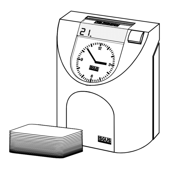
Recorder Construction Fig. 1: Total view Analogue clock Digital display for date Card funnel Pointer field with funnel shield and column pointer Programming Panel, concealed by the front cover → see chapter 4 "Getting Started" Position key Front case cover Rear case cover Chapter 2 Features 2-5... -
Page 17: Time Recorder Identification
Time Recorder Identification Electrical rating plate • Program data • The name-plate is fixed on the bottom side of the cover. The serial number is attached to the inside bottom of the unit. Electrical data Type of recorder The label with the program data (1) can be found on the operating system PROM of the CPU. -
Page 18: Chapter 3 - Installation
Chapter 3 Installation Contents ................Selecting a Location............General Conditions..........Specific Conditions for the Time Recorder ..Time Recorder Installation ..........Installation for Table Operation ......Wall Mounting............Open the Recorder ..........Close the Recorder..........Remove the Metal Back Plate ......Wall Mounting............ - Page 19 Contents The following illustration shows the time recorder box contents without options. Fig. 3: Supply Time recorder PERFECT 2020 Operating manual Warranty Registration Card 2 keys Power supply unit Fixing elements for wall mounting (2 screws, 2 plugs) Set of accessories for table operation (4 rubber feet, 3 cover caps)
-
Page 20: Selecting A Location
Selecting a Location Warning! Proper installation of the time recorder is the responsibility of the owner. All work must only be carried out by qualified personnel. The installation must comply with the requirements of the authorities having jurisdiction and all applicable safety codes and regulations that govern the installation of electrical appliances. -
Page 21: Time Recorder Installation
Time Recorder Installation Basically the PERFECT recorder is designed for table operation. No further settings are required for this type of application. Please see the instructions in the following section ”Installation for table operation”. If you have to connect additional functions such as signal operation, or master and slave clock operation, refer to the end of section "Wall mounting". -
Page 22: Wall Mounting
Select an easily accessible and vibration-free place of installation. The recorder may only be placed on a stable, slip-resistant surface. For the stability of the time recorder use the rubber feet included in the set of accessories. For this purpose clip them on by following the arrow-head indications. Also use the 3 cover caps for the metal back plate in order to seal the cable leadings. -
Page 23: Open The Recorder
Open the Recorder Insert the key into the slot on the under side of the time recorder. Press the key into the slot until the locking latch releases the front case cover. Fig. 6: Unlock the recorder Swing out the front case cover with the time recorder tilted away from you (step 1) until it can be lifted up and off the time recorder (step 2). -
Page 24: Close The Recorder
Close the Recorder Align and insert on an angle the two tabs at the top of the rear case cover into the corresponding two slots at the top of the front case cover. Swing the front case cover downwards until it meets the bottom of the rear case cover. -
Page 25: Wall Mounting
Wall Mounting The location of the mounting holes can be traced from the metal back plate of the time recorder. The metal back plate can be plugged in with the plastic housing. See previous section. The installation dimensions mentioned in this manual are recommendations which have to be adjusted for local conditions. - Page 26 Check the connection of the power cord to the screw-type terminal strip of the CPU. black black Attention The power cord must be connected to the PC board terminals that are electrically compatible with the supply voltage of the electrical outlet that the power cord is plugged into.
-
Page 27: Connect Optional Features
Connect Optional Features Only connect optional features when they are required. Optional features: − Signal operation / Check of individuals − Master clock operation − Standby operation − Slave clock operation All optional features can be used for both types of installation, i.e. table or wall mounted version. - Page 28 Connect wiring for audible signal circuit control (Signal circuit / Check of individuals → only if required. → low power signal output: 15 V DC, 50mA This connection is not polarity sensitive. Connect wiring for synchronized clock option → only if the recorder is equipped with the option module "MASTER CLOCK". →...
-
Page 29: Chapter 4 - Getting Started
Chapter 4 Getting Started Preparations..............Switch on Recorder ........... Card Funnel .............. Insert the Funnel Shield........Card Funnel Adjustment........Adjustment of the Correct Funnel Width.... Programming Panel............4-11 Time / Date ................ 4-15 Setting the Time and Date......... 4-16 Setting the Time of the Internal Quartz....4-19 Synchronizing the Analogue clock..... - Page 30 continued Print Format .............. 4-36 Column Change ............4-43 Card Lift..............4-44 Column Change Timing ........... 4-45 Standard Recorder with One Card Lift per Day.. 4-45 Standard Recorder with Two Card Lifts per Day 4-47 Graphic Recorder..........4-48 Card Lift / Line Change Timing........ 4-48 Standard Recorder..........
-
Page 31: Preparations
Preparations All settings have to be executed with the recorder opened. Under the front cover you will find further symbols and another display, see chapter 4 "Programming Panel". Follow the instructions in this chapter and keep in the order the topics are presented. Switch on Recorder The recorder is provided with a separate power switch. - Page 32 Proceeding Remove front cover If the recorder is not yet opened, remove the front cover as described in section "Open the recorder". Switch power switch to position "1". → Analogue clock is synchronised. Current time is displayed until clock synchronisation has finished.
-
Page 33: Card Funnel
Card Funnel The pointer field in front of the card funnel is designed for changeable funnel shields. The funnel shield can be inserted and can be compared with a table: it shows all column headlines. The column headlines correspond with the clocking columns on the time card. -
Page 34: Insert The Funnel Shield
Insert the Funnel Shield The funnel shield can be placed at any time (before or after commissioning ). We recommend, if the recorder is not pre-programmed, to adjust and fix the funnel shield after all the programming and test work, e.g. with an adhesive point. Remove front cover. -
Page 35: Card Funnel Adjustment
Card Funnel Adjustment This recorder can be adjusted infinitely variable to all different card widths and thicknesses. If your recorder has been programmed ex factory, these measures have already been taken. A subsequent adjustment of the card funnel may be necessary due to manufacture tolerances of time cards resp. - Page 36 Open the screw of the guide wedge until the complete guiding element can be moved. Insert a card with a certain card width, e.g. a time card, into the card funnel and adjust the card wedge. Do not adjust the card funnel too tight. Tighten screw of the guide wedge.
- Page 37 Fig. 15: Adjust card guide Variable card guide rail Fixed card guide rail Controller for card lift adjustment with transport spindle and guide Press "E" and "R" again. Keep both keys pressed until column pointer switches back to the first menu symbol (time). Switch the recorder off and on .
- Page 38 Adjustment of Card Thickness / Intensity of Print There are two red eccentric screws on the left and right side of the card funnel which serve for the adjustment of the card funnel to the correct card thickness. Both screws are accessible from above when the recorder is open.
-
Page 39: Programming Panel
Programming Panel When the recorder is closed, most of the control and display elements are not visible. All settings of commissioning and in case of subsequent changes have to be executed with the recorder opened. The programming panel contains function elements which are only necessary to set the parameters and for service purposes. - Page 40 Column pointer → Mechanic pointer → marks the current programming symbol and step in programming mode. → In booking mode the column pointer marks the current column where the time punches will be placed on a time card. Symbols for →...
- Page 41 → Card lift Shows values if card format is stored in recorder. → Only together with a new defined card format. → This symbol contains no menu item. Together with the following symbols it indicates the programming of time specific events. →...
- Page 42 Programming keys Key R → Change the displayed value. A value can be changed when flashing in the display. If the key is pressed once, the value will be increased by one. If the key is pressed continuously the value increases in fast mode.
-
Page 43: Time / Date
Time / Date The symbol is indicated by the column pointer The recorder is provided with a buffer battery controlled quartz clock with power reserve. The lithium battery stores the correct time for years in case of power failure. Setting of date and time usually is necessary only during commissioning of the recorder. - Page 44 Setting the Time and Date Attention To set the analogue clock and/or the internal quartz clock always exactly observe the procedure described as follows. It is not sufficient to set only the hands of the analogue clock. Set time first, enter date after. Proceeding Press "E"...
- Page 45 Example: The recorder switches to "Synchronise analogue clock". The current hour entered is still displayed. The field D3 indicates that the hands of the analogue clock have to be set. Set minute hand on 12h and hour hand on the full hour entered and displayed.
- Page 46 Enter current date using "R". D1 = day Value range: 01 to 31 . If you keep the key "R" pressed, fast advancing in the value range is possible Example: 31. May 1997 Confirm value using "E". Recorder switches to input of month. Select current month using "R".
- Page 47 Showing or Setting the Time of the Internal Quartz If you want to check the time of the internal quartz clock, proceed as described on this page. The command "Indication only" to the internal quartz clock doesn’t cause a manual setting of the hands. Select menu for time using "E".
-
Page 48: Programming Customer Requirements
Programming via PC. • Hint Please note that the PERFECT 2020 is designed for use around the world. In order to simplify the programming of your requirements, we have placed programming values applying to North American work places at the top of each paragraph. - Page 49 On the following pages you can find all information and details how to program the recorder and which parameters or code numbers are available. A summary of all code numbers available is printed in Appendix B "Code-table". If you have defined you own card format for your time recording and you want to program this format, please read Appendix B "Define your own card format".
-
Page 50: Calling Up The Programming Routine
Calling up the Programming Routine From version V1.19 the input of parameters is secured by a code-number. Two different access levels are distinguished: → Code-number to program all time values: - Daylight saying time change-over - Column change timing - Card lift / line change timing - Ribbon colour change - Signal circuit / Check of individuals (Option) →... - Page 51 Proceeding Press "R" (at least 2 seconds) until 4 digits are displayed. The displayed sequence is optional. The entry of the code-number begins with the left flashing digit. Enter first digit using "R". The code-number "1888" shall be entered as an example.
-
Page 52: Print Out All Parameters Programmed
Print out all Parameters Programmed The recorder offers the possibility to print out all parameters values on an empty time card. Any empty card can be used. Minimum dimension of the card: 210 x 86 mm (L x W) We recommend a card length of 230 mm. You can print out the parameters together with programming the recorder or afterwards. -
Page 53: Language Identification
Language Identification The symbol is indicated by the column pointer. In this menu the rules for the language of the weekday abbreviation is selected. Proceeding Select language identification with "R". Value range: 01 - 16 Values for applications in North America 02 = American 04 = French 05 = Spanish... - Page 54 Hint If the change-over is executed according to a freely defined program, all date and time values have to be entered every year resp. after each change-over. Please note that the change timing can only be entered for the current year. Timing for the current year that are in the past, are automatically deleted by the unit.
- Page 55 With selection of code "00" to "07", continue with step 4 With selection of code "99" continue with step 2. Confirm selection using "E". With selection of code "99", enter further values (step 3) for: - Date for normal- → daylight saying time - Time for normal- →...
- Page 56 D3 = minutes Enter minutes with "R". Value range: 00 - 59 Confirm minutes with "E". Repeat the adjustment for: D1 = 03 = Change-over from daylight saving time - to normaltime > Date < D1 = 04 = Change-over from daylight saving time - to normaltime >...
-
Page 57: Time Card Parameters
Time Card Parameters The symbol is indicated by the column pointer. This menu contains the following submenus: Selection of a pre-programmed card format (see separate time card • catalogue) Select type of recorder • Definition of period duration • Current week •... - Page 58 If a new card format is used which slightly deviates from a standard card format shown in the separate card catalogue, for example a card format with different column width, you need not to program the complete card format. You can copy a stored card format with the command "Copy" and then alter all the values which are different to the stored one.
-
Page 59: Type Of Recorder
Type of Recorder Hint You can only set values in this submenu if you want to define a new card format. See Appendix A "Define your own card format". Two different types are available: Standard recorder • Graphic recorder • Standard recorder The imprint on the time card will be executed in lines according to the... -
Page 60: Period Duration
With a graphic recorder with "creeping imprint" you can choose between an ascending and descending imprint. → IN-clocking is printed on bottom of the card, Ascending imprint: all further clockings are printed ascending. → IN-clocking is printed on top of the card, all Descending imprint: further clockings are printed descending. -
Page 61: Current Week
Definitions: → indicates the 2nd submenu "Period duration". D1 = 02: → 1 week D3 = 01: → 2 weeks = 02: = 03: → 3 weeks → 4 weeks = 04: → 5 weeks with month correction = 05: →... -
Page 62: Number Of Columns
Number of Columns Hint If a standard card format has been selected, the values shown in this submenu are pre-set and cannot be altered. The number of columns can differ form time card to time card. At the same time the number of columns is pre-set (according to type of recorder and period duration) or can be selected out of a fixed range. - Page 63 Start of Pay Period This menu function allows to alter the start of the period. For some purposes there is no need that the printing field of time cards will start with the first of the month. By indicating the date of day in this menu function the start of pay-period, therefore, can be set to any day of the month.
-
Page 64: Print Format
Print Format The symbol is indicated by the column pointer. It allows the user to define the print format of the time recorder. It can be defined whether the weekday or date are printed at every clocking, or whether the minutes are printed in decimal hours (5/100). 48 print formats are stored in the unit. - Page 65 Hours (12) 1/100 hrs AM/PM Weekday Hours 5/100 hrs Date Hours 5/100 hrs Hours 5/100 hrs Weekday Hours (12) 5/100 hrs AM/PM Date Hours (12) 5/100 hrs AM/PM Hours (12) 5/100 hrs AM/PM The following print formats correspond to the structure of the print formats no. 01 to 18.
- Page 66 Date Hours 5/100 hrs Hours 5/100 hrs Weekday Hours (12) 5/100 hrs AM/PM Date Hours (12) 5/100 hrs AM/PM Hours (12) 5/100 hrs AM/PM The print formats 37 to 48 have a lower line height. They can be used with time cards with narrow lines, e.g.
- Page 67 Proceeding Select print format with "R". Value range: 00 - 48 Definition: = Format freely defined 01 - 48 = according to table of available print formats Units destined for North America are pre-programmed with print format = 38 If you do not want to alter the value displayed, continue with step 2.
- Page 68 Confirm selection with "E". D3 = Definition of the print format. left field = imprint height right field = imprint width Select desired characters with "R". Value range: 1 - 6 Possibilities: 1 = Normal 5x9 dots e.g.: 2 = small 5x7 dots, raised e.g.: 3 = small 5x7 dots, centred e.g.:...
- Page 69 Machine Number freely defined D1 = 06 In the fields D2 and D3 you have to enter a hexadecimal value, which is printed in the code-table on the next page. This code-table is based on the ASCII-code. Example: Machine Number "A9" D2 = 41 D3 = 39 Enter values with "R".
- Page 70 Code-table for machine number freely defined This table is based on the ASCII-Code. In the table you can find the hexadecimal value for a character. Any other characters are printed as blank spaces. Space 4-42 Getting Started Chapter 4...
-
Page 71: Column Change
Column Change The symbol is indicated by the column pointer. Each time card is separated in lines and columns. The column width must be programmed so that the printer head is positioned according to the card separation. The values programmed in the menu item "Card specific parameters - number of columns"... -
Page 72: Card Lift
Card Lift The symbol is indicated by the column pointer. This menu is identical with the menu "Column change". As many line values are displayed as programmed in the menu item "Card specific parameters - Number of lines". Hint The line height can only be entered if you have selected the values "00"... -
Page 73: Column Change Timing
Column Change Timing The symbol is indicated by the column pointer. After number and dimensions of the columns and lines have been defined or selected with a standard card format , the time has to be entered from which on the clocking shall be printed in the corresponding column or line. - Page 74 Select hour with "R". Definition: D1 = column, 01 = 1. clocking column The number of columns depends on the card format selected/defined. D2 = hours Value range: 00 - 23; -- If "--" is selected, all time values for this day will be erased.
-
Page 75: Standard Recorder With Two Card Lifts Per Day
4. Enter new time with "R". 5. Quit setting by pressing "S" and select next weekday or continue as described under step 9. Quit menu "Column change timing" with "S" and switch to next menu item "Card lift timing". When time values are entered for the first time respectively after a reset, all values have to be entered for each weekday before the menu can be left. -
Page 76: Graphic Recorder
Graphic Recorder As a graphical card is not separated in IN- and OUT-clocking columns, but the days of a period are arranged horizontally, only one column change per day has to be executed. Only one column change timing per weekday has to be defined. If a time value differing from 00: .h is programmed, e.g. -
Page 77: Graphic Recorder With Leaping Imprint
If another time value than 00: h, e.g. 1: h, is programmed the clocking is printed in the line of the previous day. So shifts, overlapping the day-end can be printed in the same line. The programming is identical with the proceeding "Column change timing - standard recorder with one card lift per day". -
Page 78: Graphic Recorder With Creeping Imprint
The following example shows the programmed time values of the first weekday. The entered values are valid for all following weekdays. Name Page Month: Target Hours: Remarks: Head of the card Line 31 Punching OUT late 18:01 Line 30 16:30 Flexible time OUT Line 29 16:00... -
Page 79: Ribbon Colour Change
With descending imprint: → Time value for the start position of the card lift in the upper imprint field. → Time value for the end position of the card lift in the lower imprint field. The position for any clocking between the two values is defined by the recorder automatically (with creeping imprint). - Page 80 Hint Two identical time values for one weekday (e.g. 17:00h for black and red imprint) cannot be programmed, that means that "E" or "S" can not be pressed to switch to the next item . If no ribbon colour change is programmed, all clockings will be printed in black as this colour is pre-programmed for the printer ex factory.
-
Page 81: Signal Operation
Example: 01 06.30 h 02 08.01 h 01 11:30 h 02 14:01 h 01 16.00 h . . . and so on. If you want to erase the value 02 08 01h, the next value displayed is: 01 11 30h. Now the submenu can be left as described or further values can be entered or erased. - Page 82 Signal Times The symbol is indicated by the column pointer. External signal devices, e.g. a horn for the organisation of breaks or the plant illumination can be switched on and off at defined times by the programming of signal circuit. Contrary to the check of individuals the signal circuit works person-independent, that means the release of the signal completely takes place according to defined time intervals.
- Page 83 Example: 04 09:00 Hr 08 09:15 Hr 04 12:00 Hr 08 13:30 Hr . . . and so on. If the value "08 09 15" is erased, the next value "04 12 00" will be displayed. Now the menu can be left as described above or new time values can be entered. See proceeding on the previous pages.
-
Page 84: Quit Programming Mode
Change or Erase Signal Out-Programming The date values programmed can be changed or erased at any time. Details to the following proceeding can be find in the previous proceeding. Proceeding Call up programming routine (key "R"). Select menu "Signal out-programming" (key "S"). →... - Page 85 Hint Never set time of the analogue clock or the internal quartz clock manually. Observe always the instructions described in chapter "Set date and time". After the recorder has been adjusted to the new parameters and the analogue clock has been synchronised, the current date is displayed. Make a sample clocking with one of your time card and compare the time printed on the time card with the time of the analogue clock.
- Page 86 Example of a protocol report front Menu Card specific parameters - menu Card lift Menu Card specific parameters Card format (from left to right) type of recorder/period duration/ number of columns/number of lines Menu Imprint Print format Number freely defined, f.e. Machine number Weekdays freely defined (Example) Menu Column change...
- Page 87 Back Menu Ribbon colour change - Menu Signal out-programming Menu Ribbon colour change Timing per weekday 01 = black 02 = red Menu Signal times Signal times per weekday with signal duration in seconds Menu Signal out-programming Signal out periods during the year 01 = Signal on 00 = Signal off Chapter 4...
-
Page 88: Set Options
Set Options The options available for the recorder are installed on the recorder CPU with so- called option modules. These option modules are plugged onto the PC-board. In chapter 3 "Installation - Recorder installation" all option modules are shown in fig.7. All options installed in the recorder have to be released via the option setting routine. -
Page 89: Check Of Individuals
If the recorder is provided with the option "MASTER CLOCK" and if this option is released, code 04 01, the type of impulse for the slave clocks has to be entered. Both types of impulses, unipolar and bipolar, can be used. Slave clocks Select type of impulse with "R", field D2/D3. -
Page 90: Dcf-Connection
Proceeding Enter percentage with "R". Definition: D3 = percentage = 00 = block option check of individuals Value range: 00 - 99 Confirm with "E". Continue with "S". Next menu item "Signal out-programming". DCF-connection This option can be released if the option module "DCF" has been built in and if an external DCF-receiver has been installed. -
Page 91: Slave Clock Function
Slave clock function The "slave clock function" can be released if the option module "POLA" has been built in and if an external master clock has been installed. How this option can be released in the recorder, please see section "Set options" on the previous pages . - Page 92 The slave clocks will be synchronised after the menu "Set Date/Time" has been selected. Make sure that bipolar slave clocks switch with the same polarity. The polarity of the slave clocks can be found out by sending single impulses from the recorder.
-
Page 93: Card Face Control
Enter time of slave clocks at the recorder with "R". D2 = hours D3 = minutes Confirm hours with "E". Enter minutes with "R". Confirm minutes with "E". If the entry has been confirmed with "E", all slave clocks will be synchronised automatically to the current time of the master clock. -
Page 94: Programming Via Pc
Programming via PC To program the recorder via PC, the program "P2020" and the connection cable between recorder and PC are required. Supply: -3,5 " diskette - connection cable Programming the recorder via PC is the most elegant and easiest way to adjust the recorder to any customer setting. -
Page 95: Installation Of The Program "P2020
Installation of the Program "P2020" Make a duplicate of the program diskette. If your PC is provided with a harddisk, we recommend to copy the complete program "P2020" together with the help file from diskette on harddisk. Create a subdirectory, e.g. -
Page 96: Programming
Programming The screen is divided into 3 sections: headline, working area and bottom line. In the headline, the current file name is displayed. If no file has been loaded, the name "NONAME.PAR" is displayed. The bottom line shows all commands for programming according to the menu. -
Page 97: Chapter 5 - Operation
Chapter 5 Operation Punching at the Recorder ..........Standard Recorder........... Clocking with Manual Column Selection.... Clocking with Automatic Column Selection ..Clocking with Mixed Column Selection ....Graphic Recorder............. Standby Operation............Save Values............... Chapter 5 Operation 5-1... -
Page 98: Punching At The Recorder
Punching at the Recorder Time Card Handling With all models of time recorder, the card side on which the clock punch is to be printed must be facing towards the user. Insert the time card into the card funnel until the card comes to a stop. Wait for the time recorder to finish printing. -
Page 99: Standard Recorder
Standard Recorder IN- and OUT-clockings will be printed in separated columns. The clocking columns can be selected manually with the position key or automatically by the recorder according to the parameter setting. The column change for e.g. overtime, interruptions cannot be programmed and must be selected with the position key. Clocking with Manual Column Selection The clocking columns IN/OUT can be selected with the position key. -
Page 100: Clocking With Automatic Column Selection
Clocking with Automatic Column Selection If times for the column changes have been programmed, it is not necessary to select the clocking column with the position key. But the position key is still active. If, for example, the clocking shall be printed in a column different from the column marked by the column pointer, this column can be selected with the position key. -
Page 101: Clocking With Mixed Column Selection
Clocking with Mixed Column Selection The recorder is often programmed with mixed column selection. The first columns for the IN- and OUT-clockings in the morning and in the afternoon are defined as automatic columns, the other columns are defined as manual columns. In these manual columns extra times, e.g. -
Page 102: Graphic Recorder
Graphic Recorder There is no distinction between automatic and manual column selection if a graphic recorder is used. The column change is controlled by a time-program and is, in general, executed once a day. There is no special separation between IN- and OUT-clockings and extra time if graphical cards are used. -
Page 103: Standby Operation
Insert card into card funnel. Push card slightly down until clocking is released. Remove card from recorder. Standby Operation In order to maintain the normal operation during power failure the time recorder must be provided with a standby battery pack for the printer head. With this option, the time recorder will print up to 300 registrations over a power outage period of 24 hours. -
Page 104: Save Values
Save Values All parameter values programmed in the recorder can be saved on external data mediums. Save values via PC All values programmed in the recorder can be saved on harddisk/diskette with the function "Upload" in the Main Menu of the program "P2020". To save the parameter values of the recorder, the connection cable between unit and PC has to be installed. - Page 105 Chapter 6 Trouble Shooting Error Messages..............Reset.................. Partial-reset ............Hardware test..............Display-, printer- and memory test..... Test mode............PC-board ............Change of Fuse for Signal Output ........6-10 Chapter 6 Trouble Shooting 6-1...
-
Page 106: Chapter 6 - Error Messages
Error Messages Any error at the time recorder is indicated by a combination on the display. If the problem cannot be solved, please contact your local dealer or e-mail us at: www.service@isgustime.com To avoid any confusion with the date, all error messages begin with the letter E. Display Reason What can be done... - Page 107 Display Reason What can be done Printer head is blocked or Switch off recorder. moves too hard. Remove metal rear cover, swing-out programming → A piece of paper may be panel and check card guide, pinched in the card clean and event. remove guide.
-
Page 108: Reset
Reset You have to distinguish between 2 different resets: Complete reset • Partial reset • Attention Before each reset the set values and parameters of the recorder must be saved via PC. Complete reset A complete reset can be compared with the first start of the recorder in the factory. The card format 01 is selected and all time values will be erased. - Page 109 Proceeding Switch off recorder. Press R, E and S simultaneously and switch recorder on. Keep these keys pressed until synchronisation is finished. During the reset is executed all centre lines flash. After the reset has finished, date and time has to be entered. For time setting see chapter 4 "Getting Started - Date / Time".
-
Page 110: Hardware Test
Proceeding Recorder is switched on. Press R and E and keep pressed. Press S. Keep all 3 keys for 1 sec. until the beginning of the reset is displayed. Start reset with E. Reset can be interrupted with R and S. During the reset is executed all centre lines flash. -
Page 111: Test Mode
The line adapter build as a small circuit board is part of every supply with: Programming via PC • Before starting the test mode the circuit board has to be fixed to terminal X4 of the recorder CPU. The result is printed on the time card. If the line adapter is wrong positioned the message "NO CONNECTION"... -
Page 112: Pc-Board
PC-board The PC-board of the recorder is a multilayer board in SMD-technique. The processor is on the rear side. The PC-board is connected with the rear panel by means of fixing screws at the mains transformer. Fig. 19: PC-Board = Terminal for power supply = Terminal for signal operation →... - Page 113 = Lithium battery → Buffering of time specific parameters, real time clock component, Nominal voltage 3,3 V -5 % If nominal voltage drops below 2,5 V, change lithium battery. See position 13 "Test points". (10) = Operating system PROM Pay attention to correct position when changing the EPROM. The notch must point to the right side.
-
Page 114: Change Of Fuse For Signal Output
(17) Terminal for option module "Slave clock function/ DCF", plugged in at X6 Slave clock function (POLA): Input voltage 12 - 60 V, Input current 2 - 10 mA unipolar and bipolar impulses DCF: Voltage supply for DCF-receiver max. 12 V Output current max. -
Page 115: Chapter 7 - Maintenance
Chapter 7 Maintenance Adjustment Routine............Changing the Ribbon ............Cleaning the Time Recorder ..........Chapter 7 Maintenance 7-1... -
Page 116: Adjustment Routine
Adjustment Routine The position of the clocking on the time card is defined when programming the card lift and column change. But it may happen that the clocking is not printed exactly in the right position due to manufacturing tolerance and especially card tolerances. With this routine the position of the clocking on the time card can be adjusted in vertical and horizontal direction. -
Page 117: Changing The Ribbon
Shift clocking downwards with "E" (-). The distance between bottom line and clocking is decreased. Step width: 0,1 mm. Example: Adjustment value 58 = clocking is shifted 0,8 mm upwards. Insert time card and execute a sample clocking. Repeat steps 3 and 4 until clocking is printed in correct position. -
Page 118: Cleaning The Time Recorder
The time recorder is switched on. Press "R" and "E" simultaneously and keep these keys pressed for 1 second. → Column pointer moves to the park position right of the card funnel. Press the locking straps on the left and right side of the card funnel slightly towards the recorder and swing out the programming panel. - Page 119 Appendix A Define Your Own Card Format Create a New Card Format..........A-2 Time Card Parameters ..........A-2 Type of recorder ..........Period duration ..........Number of columns ........... Number of lines ..........Column change ............A-7 Card lift / line change..........A-8 Adjust a Pre-programmed Standard Format ....
-
Page 120: Create A New Card Format
Create a New Card Format The proceeding to create and define a new card format is identical with the proceeding in chapter 4 "Commissioning - Programming". To define a new card format the value "00" has to be selected in the menu "Card specific parameters". -
Page 121: Period Duration
Graphic recorder The clocking on the time card will be printed in columns according to the current day. The card is not separated in lines. Each clocking column corresponds to one day of the period. Graphical cards are often folded, so that all days of a period can be printed on one time card. - Page 122 Period duration The period duration refers to the time after which a payroll should be executed and the time card should be changed. Various period durations can be programmed in the unit. The period durations available depend on the type of recorder selected. Type of recorder Period durations available 1 week, 2 wk, 3 wk, 4 wk, 5 wk with month correction,...
-
Page 123: Appendix A Define Your Own Card Formats
Proceeding Select period duration with "R". Value range: 01 - 09 D1 = 02 → indicates the 2nd submenu "Type of recorder" D3 = 01 = 1 week 02 = 2 weeks 03 = 3 weeks 04 = 4 weeks 05 = 5 weeks with month correction 06 = monthly, start 1.line/1.column, continuous imprint... -
Page 124: Number Of Lines
Proceeding Select number of columns with "R". Value range: depends on type of recorder D1 = 04 → indicates the 4th submenu "Number of columns" D3 = XX = Number of columns Confirm selection with "E". Recorder switches to next submenu "Number of lines". -
Page 125: Column Change
Proceeding Select number of lines with "R". Value range: depends on type of recorder D1 = 05 → indicates the 5th submenu "Number of lines" D3 = XX = Number of lines Confirm selection with "E". Continue with "S". Next submenu "Imprint". The menu "Print Format"... -
Page 126: Card Lift / Line Change
Card lift / line change The symbol is indicated by the column pointer This menu item is identical to the menu "Column change". As many line values as programmed in the menu "Time card parameters - Number of lines" will be displayed. -
Page 127: Adjust A Pre-Programmed Standard Format
Adjust a Pre-programmed Standard Format The recorder is provided with a copy-function. By this function standard card formats can be copied and altered later on. Use of the function "Copy": Define your own card format. • If you want to define a card format which is similar to a standard card format stored in the recorder, you can copy the standard card format with the function "Copy". - Page 128 Proceeding Menu "Card specific parameters - Select card format" Select copy-function with "R". Value range: 00 - xx; Co Confirm selection with "E". Select card format to be copied with "R". Value range: 01 - xx; -- With the function "Copy" a standard card format will be changed into a card format to be freely defined.
-
Page 129: Appendix B Code-Table
Appendix B Code-Table Appendix B Code-Table B-1... - Page 130 Code-Table Summary of all codes for programming the recorder Language identification Setting Code Setting Code German Danish American Swedish English Norwegian French Finnish Spanish Polish Italian Russian Portuguese Turkish Dutch Greek Daylight saving time change-over Setting Code Setting Code no change-over change-over to EEZ - last Sunday in March - last Sunday in October...
- Page 131 01 Type of recorder Code Standard recorder with one card lift/day Standard recorder with two card lifts/day Graphic recorder with leaping imprint Graphic recorder with creeping imprint - ascending Graphic recorder with creeping imprint - descending Code 02 Period duration 1 week 2 weeks (not if type of recorder = 02) 3 weeks (only if type of recorder = 01)
- Page 132 Character Code Character Code Blank space Date Minutes Mark AM/PM 5/100 hours Mark freely defined 3-minutes-leap Weekday numeric 1/10 hours Weekday alpha freely def. 1/100 hours (approx.) Weekday alpha- according Hours to national identification 5-minute step Code Code Character height Character height x = right x = right...
- Page 133 Column change timing Setting Code 01 - xx = Column-No.., Code-Entry xxxx = Timing in HH.MM xxxx Card lift / line change timing Setting Code 00 - xx = Position, Code-Entry xxxx = Timing in HH.MM xxxx Ribbon colour change Setting Code Ribbon colour black...
- Page 134 Options Setting Code Setting Code Option disabled Slave clock function Option enabled DCF-function Standby operation Master clock function Card face control Protection with Code-Numbers Setting Code Setting Code Programming of all time 4711 Complete programming of 1888 values in the recorder the recorder B-6 Code-Table Appendix B...
-
Page 135: Appendix C Summary Of Keyboard Commands
Appendix C Keyboard Commands Keyboard commands ............Keyboard Commands for Programming ....C-2 Keyboard Commands for Punching ....... C-2 Keyboard Commands on Error Messages ..... C-3 Keyboard commands for maintenance ....C-4 Appendix C Keyboard commands C-1... -
Page 136: Keyboard Commands For Programming
Keyboard commands For easier understanding, the keyboard commands are separated into several groups: Programming, Punching, Error messages and Maintenance. Symbol "H" = Switch on recorder. Keyboard Commands for Programming Function Calls up the programming routine, recorder is switched on. approx. 2 sec. How to control the programming routine: R →... -
Page 137: Keyboard Commands On Error Messages
Calls up time setting routine, the recorder is switched on. approx. 2 sec. commands in the time setting routine: R → Selection of time and date. E → Confirmation of selection and advancing. Synchronisation of slave clocks in case of master clock function: R →... -
Page 138: Keyboard Commands For Maintenance
Test mode, recorder is switched on. R + S approx. 1 sec. Controlling: R → short pressing = Changing the minutes in single steps. keep key pressed = Fast advancing of values. E → Change of days, lines. Column and card lift if a graphic recorder is used. S →... -
Page 139: Appendix D Technical Specifications
Appendix D Technical Specifications Appendix D Technical Specifications D-1... -
Page 140: Technical Specifications
Technical Specifications Dimensions Height: 280 mm (11.02 inches) Width: 220 mm (8.67 inches) Depth: 195 mm (7.68 inches) Weight 3 kg 20 V AC +/- 10 % 50 / 60 Hz Supply voltage max. 800 mA Current consumption Power consumption max.
Need help?
Do you have a question about the PERFECT 2020 and is the answer not in the manual?
Questions and answers