Vimar 02910 Instruction Manual
Timer-thermostat
Hide thumbs
Also See for 02910:
- Installer/user quick manual (6 pages) ,
- Installer/user quick manual (4 pages)
Table of Contents
Advertisement
Quick Links
Advertisement
Table of Contents

Related Manuals for Vimar 02910


Summary of Contents for Vimar 02910
- Page 1 Instructions manual Timer-Thermostat 02910 Installer Manual...
-
Page 3: Table Of Contents
Table of Contents 1. Timer-Thermostat 02910 ………………………………………………………………………………………… 3 2. Field of application ……………………………………………………………………………………………… 3 3. Installation ………………………………………………………………………………………………………… 3 4. Connections ………………………………………………………………………………………………………… 3 4.1 Relay connection ……………………………………………………………………………………………… 3 4.2 Multi-function input …………………………………………………………………………………………… 4 4.3 Energy Probe 02960 …………………………………………………………………………………………… 4 4.3.1 Measurement of 2 or 3 phases………………………………………………………………………………… 5 4.3.2 Saving the consumption data log ………………………………………………………………………………... - Page 4 8.12 Info about the device ……………………………………………………………………………………… 8.13 Lock/unlock PIN setting …………………………………………………………………………………… 9. Parameters table ……………………………………………………………………………………………… 10. Alarms …………………………………………………………………………………………………………… 11. Cleaning the device …………………………………………………………………………………………… 12. Installation rules ……………………………………………………………………………………………… 13. Regulatory compliance ………………………………………………………………………………………...
-
Page 5: Timer-Thermostat 02910
1. Timer-Thermostat 02910 Wall-mounting, battery-powered timer-thermostat with interface with capacitive keys and equipped with user-friendly functions to facilitate energy saving. Designed to control heating and air-conditioning via C, NC, NO relay output. Equipped with multi-function input for remote control (reduction, activation, summer/winter switching). -
Page 6: Multi-Function Input
1 and 4 (outer pair) and the other between pins 2 and 3 (inner pair). Take care to keep consistent connections at the terminals. For example: • 5V orange • A blue • B white-blue • GND white-orange 02910 MADE IN ITALY – –T40 NO NC C... -
Page 7: Measurement Of 2 Or 3 Phases
4.3.1 Measurement of 2 or 3 phases The energy probe 02960 comes with a single current probe (for measuring the consumption/ production of a single phase); to measure more than one phase it is essential to have more current probes 01457 (one for each additional phase to be measured). Once connected, you must enable the new channel (the new phase to be measured) using the menu described in par. - Page 8 ENERGY METER 02960 120-230V 50/60Hz 230/400V 50/60Hz 127/220V 50/60Hz MADE IN ITALY RS-485 Fig. 3: Measurement of the total consumption of a system, also with (single-phase) loads distrib- uted over multiple phases.
- Page 9 ENERGY METER 02960 120-230V 50/60Hz 230/400V 50/60Hz 127/220V 50/60Hz MADE IN ITALY RS-485 INVERTER Fig. 4: Measurement of net consumption or generation with a photovoltaic system installed. In cases of generation via a photovoltaic panel (fed into the national grid), the probe will record a NEGATIVE value, which corresponds to energy generation (the opposite of consumption).
- Page 10 ENERGY METER 02960 120-230V 50/60Hz 230/400V 50/60Hz 127/220V 50/60Hz MADE IN ITALY RS-485 INVERTER Fig. 5: Measurement of differentiable consumption and generation with a photovoltaic system installed. Observe the direction of installation of the current probe S2: in cases of generation via a photovoltaic panel, the probe will record a NEGATIVE value, that corresponds to energy generation (as opposed to consumption).
-
Page 11: Inserting New / Replacement Batteries
5. Inserting new / replacement batteries When replacing batteries, remove the front panel by raising it with a screwdriver. Replace the batteries with Alkaline 1.5V "AA" batteries. CAUTION! In case of replacement, dispose of batteries in the specific differentiated collection bins Fig. -
Page 12: Display
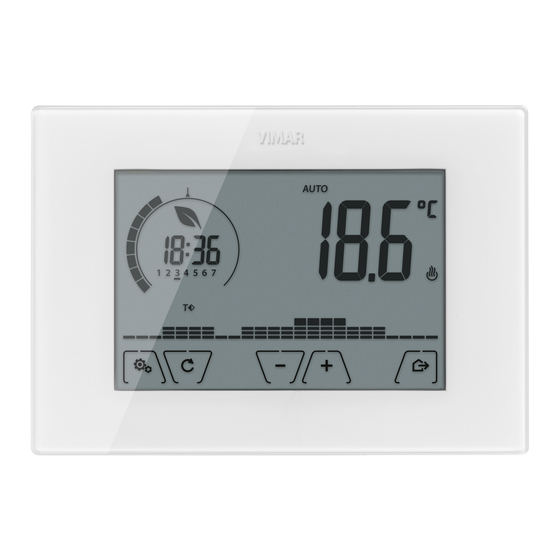
6. Display The touchscreen display allows you to control the system using the following buttons and icons: Fig. 7: Graphical interface and buttons A: Ring indicating consumption level and energy savings indicator B: Battery charge status C: Operating mode D: Away E: Confirm or energy log navigation F-G: Menu navigation and setting parameters H: Back... -
Page 13: Functions Of The Buttons
6.1 Functions of the buttons : increases the numerical values. When it "disappears" from the display it means that the value cannot be increased any more. : decreases the numerical values. When it "disappears" from the display it means that the value cannot be decreased any more. -
Page 14: Symbols
6.2 Symbols Depending on the different operating modes, the display shows the following icons: : Calibration : Entering the PIN : Timed manual operation : Away : Manual : Nighttime reduction : Antifreeze : Switched off (OFF) : Automatic operation : Multi-function input ON : Alarm : Air conditioning... -
Page 15: Locking The Interface Via Pin
6.3 Locking the interface via PIN The timer-thermostat lets you set a password which inhibits any change to the operating mode (eg switching from Manual to OFF), limits setting the temperature values and, more generally, blocks access to the configuration menu. This feature is useful to prevent the thermostat being used by unauthorized persons: the device prompts you to enter the PIN, indicating a shutdown with the icon. -
Page 16: Ecometer
Each sector can be composed of 1, 2 or 3 dashes: equivalent to “T away” ( equivalent to “T economy” ( equivalent to “T comfort” ( The clock shows the current time. The indicator of the day of the week highlights the current day with a dash under the number associated with it (eg, 4 = Thursday). -
Page 17: Consulting The Energy Probe (If Enabled)
6.4.3 Consulting the energy probe (if enabled) Indicator for Comparison ring with production/consumption the average power Measured power Unit of measurement Button for consulting energy log Fig. 11: Typical screen for consulting the energy probe This option is used to consult data on the instantaneous power and energy consumed/generated by the system and measured instantly by the energy probe. - Page 18 The information provided is represented as follows: indicates consumption less than half the average consumption indicates consumption in line with the average indicates consumption 1.5 times higher than the average The circular ring (only when consulting the instantaneous power) represents the current level of consumption compared to the maximum level recorded in the last 24 h (ring complete with all the dashes = maximum consumption);...
- Page 19 • (historical data reset): this option lets you delete ALL the historical data saved by the energy probe; since this operation cannot be undone, an additional confirmation screen is displayed (YES to delete and NO not to delete). • (hourly consumption): enables you to scroll one by one through the hours prior to the current one;...
-
Page 20: Operating Mode
7. Operating mode The timer-thermostat 02910 is able to regulate the temperature according to the following operating modes: • Switched off (OFF): switches the system off • Manual (ON): lets you set the environment temperature set-point manually • AUTO: lets you set a control program that compares the room temperature with the value set for each quarter of an hour of the current day;... -
Page 21: Manual
7.2 Manual In this mode the device operates as a simple thermostat and regulates the ambient temperature, taking it to the value set by the user. When MANUAL mode is active, the icon is displayed above the temperature indicator. Fig. 14: Typical screen for Manual mode The set point can always be changed via Fig. -
Page 22: Auto
7.3 Auto This is the typical mode of operation of the timer-thermostat. The device automatically changes the ambient temperature according to the time of day and the day of the week, it minimizes user intervention thereby optimizing comfort and energy savings; three different temperatures can be set to cover the needs of normal use, user away or nighttime reduction in the environment. -
Page 23: Timed Manual
7.4 Timed manual This mode allows you to exit the AUTO program (you enter MANUAL mode) for a certain time after which the timer-thermostat will return to AUTO mode. For example: take the ambient temperature to 25°C for 2 hours and then resume the Auto program. Activation is carried out starting from AUTO mode and is recognizable by the icon displayed above the temperature indicator. -
Page 24: Away
7.5 Away This mode is useful to achieve energy savings quickly and effectively whenever the user leaves the reg- ulated room. In "Away" mode the system makes the adjustment according to the "away temperature" setpoint The Away mode can only be activated by touching The display will show the "away temperature"... -
Page 25: Antifreeze
Fig. 21: Antifreeze mode 7.7 Remote reduction Remote reduction is a useful way to "centralize" energy saving if there are multiple 02910 thermostats in different rooms of the same house. Example: Before going to bed, using a simple switch, all the thermostats in the house are set onto "reduc- tion"... -
Page 26: Remote Auto
Fig. 22: Input in Remote reduction mode 7.8 Remote auto This mode is typically used in applications where you want to remotely enable or disable temperature control of a room and limit the functions that can be performed by the user. This mode comes into operation when the multi-function input is activated (see par. -
Page 27: Settings Menu
8. Settings menu From the settings menu you can configure all the features of the timer-thermostat. On the main screen tap the icon. From the main menu, using will display the following (flashing) symbols in succession, which provide access to the corresponding submenus: operating mode setting setting the time and day of the week air-conditioning/heating setting... -
Page 28: Setting The Time And Day Of The Week
8.1 Operating mode setting This menu is used to select the operating mode of the device: • Manual • Automatic • • Antifreeze (only if the thermostat is set on "heating") Using select the desired mode and confirm with 8.2 Setting the time and day of the week This menu lets you set the time and day of the week. -
Page 29: Selecting The Day Of The Week
8.5.1 Selecting the day of the week As soon as you enter the menu, the display shows a flashing dash for the day to which the current programming refers (for example: 1234567 = Tuesday). Using select the day of the week to program and confirm with 8.5.2 Temperature selection After confirming the day to program, the display shows the screen for setting the temperatures associated with the different times of the day. -
Page 30: Temperature Setting
Using you can move respectively between the hours of the day and move forwards or backwards 15 minutes at a time. During the movement, as well as the clock, also the "dashes" indicate the time of day in which you are working. In addition, below the numbers associated with the days of the week, you will see an icon that identifies the temperature set for that specific time. -
Page 31: Away Temperature
8.6.1 Away temperature The menu, via , lets you increase/decrease the value of the away temperature The away temperature is an intermediate temperature geared to obtain substantial energy savings during periods when the user is away. The away temperature differs depending on whether you are in the heating or air-conditioning mode. -
Page 32: Thermal Delta In Nighttime Reduction Mode
8.6.5 Thermal delta in nighttime reduction mode The menu, via , lets you set the difference between the remote reduction tem- perature and Tcomfort temperature. The remote reduction mode can only be activated via the multi-function input. The hysteresis is a temperature increase/decrease that is applied to the Tcomfort temperature when the multifunction input is activated). - Page 33 • (summer/winter switching): the multi-function input automatically switches the timer-thermostat onto air-conditioning mode (when on) or heating mode (when off). This option is useful for centralized systems in which the air-conditioning or heating mode is performed at the level of the entire building and impacts on many sub-environments. to confirm your choice.
-
Page 34: Energy Probe Setting
8.10 Energy probe setting When the energy probe is connected to the device, the menu is accessible and allows you to enable or disable the measurement of each phase or configure the "power threshold" alarm. There are the following submenus: •... -
Page 35: Info About The Device
8.12 Info about the device This menu lets you view information related to the thermostat and reset the device. you can select: • : displays the number of hours that the timer-thermostat relay has been on (the same as the number of hours of operation of the system). -
Page 36: Parameters Table
9. Parameters table Reso- Function Parameters Value range Default value lution [Off, Reduction, Multi-function input IN selection Activation, Heating/Air-Con.] Nighttime Reduction δ (red. offset) [1,..,6]°C 0.1°C 4°C Selection Temperature control mode [Heat., Air-con.] Heating TempCtrl Control algorithm Algorithm [ON/OFF, PID] ON/OFF Hysteresis (ON/OFF) (Differential) -
Page 37: Alarms
(Away-Heat.) , 10..35]°C 0.1°C 15°C (Economy-Heat.) [10,..,35]°C 0.1°C 18°C (Comfort-Heat.) [10,..,35]°C 0.1°C 20°C (Away-Aircon.) [10,..,35,OFF]°C 0.1°C 28°C Temperature set-point (Economy-Aircon.) [10,..,35]°C 0.1°C 26°C (Comfort-Aircon.) [10,..,35]°C 0.1°C 23°C (Manual-Heat.) [10,..,35]°C 0.1°C 18°C (Manual-Aircon.) [10,..,35]°C 0.1°C 26°C (Antifreeze) [4,..,10]°C 0.1°C 5°C (Heating) for Heating Prog. - Page 38 Viale Vicenza, 14 - 36063 Marostica VI - Italy Tel. +39 0424 488 600 - Fax (Italy) +39 0424 488 188 02910 installer 01 1406 Fax (Export) +39 0424 488 709 VIMAR - Marostica - Italy www.vimar.com...
Need help?
Do you have a question about the 02910 and is the answer not in the manual?
Questions and answers