Juniper SRX5800 Hardware Manual
Services gateway
Hide thumbs
Also See for SRX5800:
- Hardware manual (536 pages) ,
- Getting started manual (37 pages) ,
- Installation instructions manual (20 pages)

Subscribe to Our Youtube Channel
Related Manuals for Juniper SRX5800


Summary of Contents for Juniper SRX5800
- Page 1 SRX5800 Services Gateway Hardware Guide Modified: 2015-10-22 Copyright © 2015, Juniper Networks, Inc.
- Page 2 END USER LICENSE AGREEMENT The Juniper Networks product that is the subject of this technical documentation consists of (or is intended for use with) Juniper Networks software. Use of such software is subject to the terms and conditions of the End User License Agreement (“EULA”) posted at http://www.juniper.net/support/eula.html.
-
Page 3: Table Of Contents
SRX5800 Services Gateway Chassis ........ - Page 4 Power System Description ......... 87 SRX5800 Services Gateway Power System Overview ..... . 87 SRX5800 Services Gateway High-Capacity AC Power Supply .
- Page 5 DC Power Circuit Breaker Requirements for the SRX5800 Services Gateway . . . 137 DC Power Source Cabling for the SRX5800 Services Gateway ....138 Chapter 13 Cable Specifications and Pinouts .
- Page 6 Tools and Parts Required to Unpack the SRX5800 Services Gateway ..155 Unpacking the SRX5800 Services Gateway ......155 Verifying the SRX5800 Services Gateway Parts Received .
- Page 7 Connections ........... 219 Grounding the SRX5800 Services Gateway ......220 Chapter 20 Connecting the SRX5800 Services Gateway to External Devices .
- Page 8 SRX5K-SCBE and SRX5K-RE-1800X4 in a Chassis Cluster Fail ..273 Juniper Networks Technical Assistance Center ......275...
- Page 9 Replacing Line Cards and Module Components ..... . 295 Replacing SRX5800 Services Gateway IOCs ......295 Removing an SRX5800 Services Gateway IOC .
- Page 10 Contacting Customer Support ........385 Return Procedure for the SRX5800 Services Gateway ....386 Listing the SRX5800 Services Gateway Component Serial Numbers with the Command-Line Interface .
- Page 11 Agency Approvals and Regulatory Compliance Information ... 439 SRX5800 Services Gateway Agency Approvals ......439 SRX5800 Services Gateway Compliance Statements for EMC Requirements .
- Page 12 SRX5800 Services Gateway Hardware Guide Copyright © 2015, Juniper Networks, Inc.
- Page 13 Line Card and Module Description ........33 Figure 18: Interoperability Matrix for SRX5400, SRX5600, and SRX5800 Services Gateways .
- Page 14 Figure 61: Power Distribution from DC and High-Capacity AC Power Supplies in the SRX5800 Services Gateway Chassis ......89 Figure 62: High-Capacity AC Power Supply .
- Page 15 Chapter 17 Installing the SRX5800 Services Gateway ......165 Figure 76: Removing a Power Supply Before Installing the Services Gateway (Standard-Capacity Power Supply Shown, High-Capacity Similar) .
- Page 16 Chapter 19 Grounding the SRX5800 Services Gateway ......219 Figure 107: Connecting the Grounding Cable ......221 Chapter 20 Connecting the SRX5800 Services Gateway to External Devices .
- Page 17 Supply ............382 Copyright © 2015, Juniper Networks, Inc.
- Page 18 Figure 164: Serial Number ID Label ........388 Figure 165: SRX5800 Chassis Serial Number Label ..... . 388 Figure 166: AC Power Supply Serial Number Label .
- Page 19 Hardware Component Overview ........5 Table 3: SRX5800 Services Gateway Card Cage Slots ..... . 6 Table 4: SCB Slot Mapping and Functionality .
- Page 20 Table 26: Services Gateway Environmental Specifications ....106 Table 27: SRX5800 Services Gateway Zoning ......108 Table 28: Sample Power Requirements for an SRX5800 Services Gateway with SCB1 and RE1 .
- Page 21 Chapter 15 Unpacking the SRX5800 Services Gateway ......155 Table 54: Parts List for a Fully Configured Services Gateway ....157 Table 55: Accessory Box Parts List .
- Page 22 SRX5800 Services Gateway Hardware Guide xxii Copyright © 2015, Juniper Networks, Inc.
-
Page 23: About The Documentation
® To obtain the most current version of all Juniper Networks technical documentation, see the product documentation page on the Juniper Networks website at http://www.juniper.net/techpubs/ If the information in the latest release notes differs from the information in the documentation, follow the product Release Notes. -
Page 24: Table 1: Notice Icons
SRX5800 Services Gateway Hardware Guide Table 1: Notice Icons Icon Meaning Description Informational note Indicates important features or instructions. Caution Indicates a situation that might result in loss of data or hardware damage. Warning Alerts you to the risk of personal injury or death. -
Page 25: Documentation Feedback
We encourage you to provide feedback, comments, and suggestions so that we can improve the documentation. You can provide feedback by using either of the following methods: Online feedback rating system—On any page at the Juniper Networks Technical Documentation site at , simply click the http://www.juniper.net/techpubs/index.html... -
Page 26: Requesting Technical Support
7 days a week, 365 days a year. Self-Help Online Tools and Resources For quick and easy problem resolution, Juniper Networks has designed an online self-service portal called the Customer Support Center (CSC) that provides you with the following features: Find CSC offerings: http://www.juniper.net/customers/support/... - Page 27 About the Documentation For international or direct-dial options in countries without toll-free numbers, see http://www.juniper.net/support/requesting-support.html Copyright © 2015, Juniper Networks, Inc. xxvii...
- Page 28 SRX5800 Services Gateway Hardware Guide xxviii Copyright © 2015, Juniper Networks, Inc.
-
Page 29: Overview
System Overview on page 3 Hardware Component Overview on page 5 Chassis Description on page 19 Line Card and Module Description on page 33 Cooling System Description on page 83 Power System Description on page 87 Copyright © 2015, Juniper Networks, Inc. - Page 30 SRX5800 Services Gateway Hardware Guide Copyright © 2015, Juniper Networks, Inc.
-
Page 31: System Overview
SRX5800 Services Gateway Description on page 3 SRX5800 Services Gateway Description The SRX5800 Services Gateway is a high-performance, highly scalable, carrier-class security device with multi-processor architecture. The services gateway provides 12 slots that you can populate with 2 or 3 Switch Control... - Page 32 SRX5800 Services Gateway Hardware Guide Copyright © 2015, Juniper Networks, Inc.
-
Page 33: Hardware Component Overview
For an open-frame rack, center-mounting is preferable because of the more even distribution of weight. Related Installing the SRX5800 Services Gateway Mounting Hardware for a Four-Post Rack Documentation or Cabinet on page 161 Installing the SRX5800 Services Gateway Mounting Hardware in an Open-Frame Rack... -
Page 34: Srx5800 Services Gateway Card Cage And Slots
IOC, Flex IOC, or MPC IOC3 0 (leftmost) 11 (rightmost) NOTE: For operational and cooling efficiency in SRX5800 Services Gateways, we recommend that slot 0 and 11 be filled last. Related SRX5800 Services Gateway Midplane Description on page 22 Documentation... -
Page 35: Srx5800 Services Gateway Interface Card Description
Chapter 2: Hardware Component Overview SRX5800 Services Gateway Interface Card Description Interface cards are cards that support physical interfaces that you use to connect the services gateway to your data network. Three different types of interface cards are available: I/O Cards (IOCs) have fixed interface ports on the front panel of the card. -
Page 36: Figure 1: Typical Iocs
SRX5800 Services Gateway Hardware Guide Figure 1: Typical IOCs Figure 2 on page 8 shows a Flex IOC with two typical port modules installed. Figure 2: Flex IOC with Port Modules Flex IOC 4x10GE-XFP port module in slot 0 16x1GE-TX... -
Page 37: Srx5800 Services Gateway Spc Description
Replacing SRX5800 Services Gateway Flex IOCs on page 300 Replacing SRX5800 Services Gateway MPCs on page 318 SRX5800 Services Gateway Card Cage and Slots on page 6 SRX5800 Services Gateway Field-Replaceable Units on page 279 SRX5800 Services Gateway SPC Description... -
Page 38: Srx5800 Services Gateway Host Subsystem Description
SRX5800 Services Gateway Card Cage and Slots on page 6 Documentation SRX5800 Services Gateway Field-Replaceable Units on page 279 Maintaining Interface Cards and SPCs on the SRX5800 Services Gateway on page 259 Troubleshooting SRX5800 Services Gateway SPCs on page 271 Replacing SRX5800 Services Gateway SPCs on page 308... -
Page 39: Switch Control Board Srx5K-Scb Overview
The host subsystem has three LEDs that display its status. The host subsystem LEDs are located in the middle of the craft interface. Related SRX5800 Services Gateway Craft Interface Host Subsystem LEDs on page 26 Documentation Switch Control Board SRX5K-SCB Overview on page 11... -
Page 40: Figure 5: Srx5K-Scb
SRX5800 Services Gateway Hardware Guide Figure 5: SRX5K-SCB The SRX5800 Services Gateway must have at least two SCBs installed, and you can install a third SCB for switch fabric redundancy. NOTE: The SRX5800 Services Gateway does not support a redundant SCB (third SCB) card if SRX5K-SPC-4-15-320 (SPC2) is installed on the device. -
Page 41: Switch Control Board Srx5K-Scbe Overview
Related SRX5800 Services Gateway Card Cage and Slots on page 6 Documentation Maintaining the SRX5800 Services Gateway Host Subsystem and SCBs on page 257 Replacing an SRX5800 Services Gateway SCB on page 328 Switch Control Board SRX5K-SCBE Overview The SRX5000 line enhanced Switch Control Board (SRX5K-SCBE) caters to high-end security markets requiring support for higher capacity traffic. -
Page 42: Switch Control Board Srx5K-Scb3 Overview
The SRX5K-SCB3 (SCB3) caters to high-end security markets requiring support for higher capacity traffic, greater interface density (slot and capacity scale), and improved services. The SCB3 is supported on SRX5400, SRX5600, and SRX5800 Services Gateways. The SCB3 supports the standard midplane and the enhanced midplane. -
Page 43: Routing Engine Srx5K-Re-13-20 Overview
SCB1 (see Figure 8 on page 16). A USB port on the Routing Engine accepts a USB memory card that allows you to load Junos OS. Copyright © 2015, Juniper Networks, Inc. -
Page 44: Routing Engine Srx5K-Re-1800X4 Overview
SRX5400, SRX5600, and SRX5800 Services Gateway Card Reference www.juniper.net/techpubs/ Related Replacing the SRX5800 Services Gateway Routing Engine on page 332 Documentation Routing Engine SRX5K-RE-1800X4 Overview The enhanced Routing Engine is an Intel-based PC platform that runs Junos OS. Software... -
Page 45: Srx5K-Re-1800X4 Routing Engine Boot Sequence
Related Switch Control Board SRX5K-SCBE Overview on page 13 Documentation SRX5800 Services Gateway Component Redundancy The following major hardware components are redundant: Switch Control Boards (SCBs)—The host subsystem consists of a Routing Engine installed in an SCB. The device must have one host subsystem installed. You can install a second SCB for increased throughput, and a third SCB for redundancy. - Page 46 The SRX5800 Services Gateway does not support a redundant SCB (third SCB) card if SRX5K-SPC-4-15-320 (SPC2) is installed on the device. If you have installed an SPC2 on an SRX5800 Services Gateway with a redundant SCB card, make sure to remove the redundant SCB card.
-
Page 47: Chassis Description
SRX5800 Services Gateway Cable Manager Description on page 24 SRX5800 Services Gateway Craft Interface Overview on page 24 SRX5800 Services Gateway Craft Interface Alarm LEDs and Alarm Cutoff/Lamp Test Button on page 25 SRX5800 Services Gateway Craft Interface Host Subsystem LEDs on page 26... -
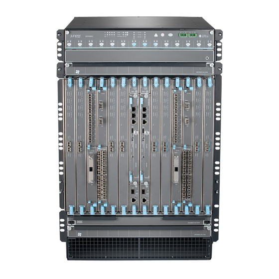
Page 48: Figure 10: Front View Of A Fully Configured Services Gateway Chassis
To meet safety and electromagnetic interference (EMI) requirements and to ensure proper operation, you must properly ground the services gateway chassis before connecting power. See “Grounding the SRX5800 Services Gateway” on page 220 for instructions. CAUTION: Before removing or installing components of a services gateway, attach an ESD strap to an ESD point and place the other end of the strap around your bare wrist. -
Page 49: Figure 11: Rear View Of A Fully Configured Ac-Powered Services Gateway
Chapter 3: Chassis Description Figure 11: Rear View of a Fully Configured AC-Powered Services Gateway Chassis Copyright © 2015, Juniper Networks, Inc. -
Page 50: Srx5800 Services Gateway Midplane Description
SRX5800 Services Gateway Hardware Guide Figure 12: Rear View of a Fully Configured DC-Powered Services Gateway Chassis Related Preventing Electrostatic Discharge Damage to the SRX5800 Services Gateway on Documentation page 402 SRX5800 Services Gateway Physical Specifications on page 104 SRX5800 Services Gateway Power System Overview on page 87... -
Page 51: Figure 13: Midplane
Related SRX5800 Services Gateway Chassis on page 19 Documentation SRX5800 Services Gateway Card Cage and Slots on page 6 SRX5800 Services Gateway Interface Card Description on page 7 Switch Control Board SRX5K-SCB Overview on page 11 SRX5800 Services Gateway Power System Overview on page 87... -
Page 52: Srx5800 Services Gateway Cable Manager Description
Figure 14: Cable Management System Maintenance linkage Release handles Related Replacing the SRX5800 Services Gateway Cable Manager on page 292 Documentation SRX5800 Services Gateway Craft Interface Overview The craft interface shows you status and troubleshooting information at a glance and... -
Page 53: Test Button
Chapter 3: Chassis Description Related SRX5800 Services Gateway Craft Interface Host Subsystem LEDs on page 26 Documentation SRX5800 Services Gateway Craft Interface Power Supply LEDs on page 27 SRX5800 Services Gateway Craft Interface Card OK/Fail LEDs on page 27 SRX5800 Services Gateway Craft Interface Fan LEDs on page 28... -
Page 54: Srx5800 Services Gateway Craft Interface Host Subsystem Leds
Causes all LEDs on the craft interface to light (for testing) when pressed and held. Related SRX5800 Services Gateway Craft Interface Alarm Relay Contacts on page 30 Documentation SRX5800 Services Gateway Craft Interface Overview on page 24 SRX5800 Services Gateway Craft Interface Host Subsystem LEDs on page 26... -
Page 55: Srx5800 Services Gateway Craft Interface Host Subsystem Leds
SRX5800 Services Gateway Craft Interface Overview on page 24 Documentation SRX5800 Services Gateway Craft Interface Host Subsystem LEDs on page 26 SRX5800 Services Gateway Craft Interface Card OK/Fail LEDs on page 27 SRX5800 Services Gateway Craft Interface Card OK/Fail LEDs Each slot in the card cage has a pair of LEDs on the craft interface that indicates the status of the card installed in it. -
Page 56: Srx5800 Services Gateway Craft Interface Fan Leds
Related SRX5800 Services Gateway Craft Interface Overview on page 24 Documentation SRX5800 Services Gateway Craft Interface Card OK/Fail LEDs on page 27 SRX5800 Services Gateway Craft Interface Online Buttons on page 28 SRX5800 Services Gateway Craft Interface Online Buttons The craft interface has a row of Online/Offline buttons along its lower edge. Each button corresponds to one slot in the card cage. - Page 57 ---Offlined by cli command--- Online 1024 The command output indicates the MPC is offline. Bring the MPC online for the first time by using the following CLI command: user@host> request chassis fpc slot 1 online node0: -------------------------------------------------------------------------- Copyright © 2015, Juniper Networks, Inc.
-
Page 58: Srx5800 Services Gateway Craft Interface Alarm Relay Contacts
Documentation SRX5800 Services Gateway Craft Interface Fan LEDs on page 28 SRX5800 Services Gateway Craft Interface Alarm Relay Contacts on page 30 SRX5800 Services Gateway Craft Interface Alarm Relay Contacts The craft interface has two alarm relay contacts for connecting the device to external... - Page 59 Connects the alarm relay to the current source for the external alarm-reporting device. Normally Open Connects the alarm relay to an external alarm-reporting device that activates when the circuit between C and NC is open. Copyright © 2015, Juniper Networks, Inc.
-
Page 60: Figure 17: Example Alarm Reporting Device
SRX5800 Services Gateway Craft Interface Online Buttons on page 28 Connecting an SRX5800 Services Gateway to an External Alarm-Reporting Device on page 226 Alarm Relay Contact Wire Specifications for the SRX5800 Services Gateway on page 144 Copyright © 2015, Juniper Networks, Inc. -
Page 61: Line Card And Module Description
Line Card and Module Description SRX5400, SRX5600, and SRX5800 Services Gateway Card Overview on page 34 Cards Supported on SRX5400, SRX5600, and SRX5800 Services Gateways on page 35 Services Processing Card SRX5K-SPC-2-10-40 Specifications on page 36 Services Processing Card SRX5K-SPC-4-15-320 Specifications on page 40... -
Page 62: Srx5400, Srx5600, And Srx5800 Services Gateway Card Overview
The cards described in this guide let you upgrade and customize your SRX5400, SRX5600, or SRX5800 Services Gateway to suit the needs of your network. The following types of cards are available for the SRX5400, SRX5600, and SRX5800 Services Gateways: I/O cards (IOCs) provide additional physical network connections to the services gateway. -
Page 63: Cards Supported On Srx5400, Srx5600, And Srx5800 Services Gateways
Chapter 4: Line Card and Module Description Related Cards Supported on SRX5400, SRX5600, and SRX5800 Services Gateways on page 35 Documentation Cards Supported on SRX5400, SRX5600, and SRX5800 Services Gateways Table 12 on page 35 describes the cards and other modules supported on the SRX5400, SRX5600, and SRX5800 Services Gateways. -
Page 64: Services Processing Card Srx5K-Spc-2-10-40 Specifications
12.1X47-D15 12.1X47-D15 Figure 18 on page 36 is an interoperability matrix that describes the compatibility between various interface cards for the SRX5400, SRX5600, and SRX5800 Services Gateways. Figure 18: Interoperability Matrix for SRX5400, SRX5600, and SRX5800 Services Gateways Related SRX5400, SRX5600, and SRX5800 Services Gateway Card Overview on page 34... -
Page 65: Figure 19: Services Processing Card Srx5K-Spc-2-10-40
CAUTION: If you are having a problem running a Juniper Networks device that is using a third-party optic or cable, the Juniper Networks Technical Assistance Center (JTAC) can help you diagnose the source of the problem. Your JTAC engineer might recommend that you check the third-party optic or cable and potentially replace it with an equivalent Juniper Networks optic or cable that is qualified for the device. - Page 66 SRX5800 Services Gateway Hardware Guide Two Gigabit Ethernet interfaces that allow control information, route information, and statistics to be sent between the Routing Engine and the CPU on the SPCs. Two interfaces from the SCBs that enable the boards to be powered on and controlled.
- Page 67 Green–Chassis cluster control port link is active. Off–No link. ENABLE LED, one for each of the two ports CHASSIS CLUSTER CONTROL 0 CHASSIS CLUSTER CONTROL 1 Green–The chassis cluster control port is enabled. Off–The chassis cluster control port is disabled. Copyright © 2015, Juniper Networks, Inc.
-
Page 68: Services Processing Card Srx5K-Spc-4-15-320 Specifications
Serial number ID label AA567 8 Related Cards Supported on SRX5400, SRX5600, and SRX5800 Services Gateways on page 35 Documentation Services Processing Card SRX5K-SPC-4-15-320 Specifications The SRX5K-SPC-4-15-320 Services Processing Card (SPC) contains four Services Processing Units (SPUs), which provide the processing power to run integrated services... -
Page 69: Figure 21: Services Processing Card Srx5K-Spc-4-15-320
CAUTION: If you are having a problem running a Juniper Networks device that is using a third-party optic or cable, the Juniper Networks Technical Assistance Center (JTAC) can help you diagnose the source of the problem. Your JTAC engineer might recommend that you check the third-party optic or cable and potentially replace it with an equivalent Juniper Networks optic or cable that is qualified for the device. - Page 70 Requirement NOTE: In the SRX5600 and SRX5800 Services Gateways, you must have high-capacity power supplies (either AC or DC) and high-capacity fan trays installed in the services gateway in order to install and use SRX5K-SPC-4-15-320 SPCs. If you do not have high-capacity power supplies and fan trays installed, the services gateway will log an alarm condition when it recognizes the SRX5K-SPC-4-15-320 SPCs.
- Page 71 Green–Chassis cluster control port link is active. Off–No link. ENABLE LED, one for each of the two ports CHASSIS CLUSTER CONTROL 0 CHASSIS CLUSTER CONTROL Green–The chassis cluster control port is enabled. Off–The chassis cluster control port is disabled. Copyright © 2015, Juniper Networks, Inc.
-
Page 72: I/O Card Srx5K-40Ge-Sfp Specifications
Serial number ID label AA567 8 Related Cards Supported on SRX5400, SRX5600, and SRX5800 Services Gateways on page 35 Documentation I/O Card SRX5K-40GE-SFP Specifications The SRX5K-40GE-SFP I/O card (IOC) is optimized for Ethernet density and supports 40 Gigabit Ethernet ports (see Figure 23 on page 45). -
Page 73: Figure 23: Ioc Srx5K-40Ge-Sfp
1000BASE-SX (model numbers SRX-SFP-1GE-SX, SRX-SFP-1GE-SX-ET) 1000BASE-T (model numbers SRX-SFP-1GE-T, SRX-SFP-1GE-T-ET) Controls None Supported Slots SRX5600–Any slot except bottom slots SRX5800–Any slot except center slots , or Power Requirement 312 W typical, 365 W maximum Weight Approximately 13 lb (5.9 kg) -
Page 74: I/O Card Srx5K-4Xge-Xfp Specifications
OK /F AIL Serial number ID label AA567 8 Related Cards Supported on SRX5400, SRX5600, and SRX5800 Services Gateways on page 35 Documentation I/O Card SRX5K-4XGE-XFP Specifications The SRX5K-4XGE-XFP I/O card (IOC) supports four 10-Gigabit Ethernet ports (see Figure 25 on page 47). -
Page 75: Figure 25: Ioc Srx5K-4Xge-Xfp
10GBASE-LR (model numbers SRX-XFP-10GE-LR and SRX-XFP-10GE-LR-ET 10GBASE-SR (model numbers SRX-XFP-10GE-SR and SRX-XFP-10GE-SR-ET ) Controls None Supported Slots SRX5600–Any slot except bottom slots SRX5800–Any slot except center slots , or Power Requirement 312 W typical, 365 W maximum Weight Approximately 13 lb (5.9 kg) -
Page 76: Modular Port Concentrator (Srx5K-Mpc) Specifications
You can install MPCs in any of the slots that are not reserved for Switch Control Boards (SCBs). If a slot in the SRX5400, SRX5600, or SRX5800 Services Gateway card cage is not occupied by a card, you must install a blank panel to shield the empty slot and to allow cooling air to circulate properly through the services gateway. -
Page 77: Figure 27: Srx5K-Mpc
Chapter 4: Line Card and Module Description Figure 27: SRX5K-MPC MPC (empty) Copyright © 2015, Juniper Networks, Inc. - Page 78 SRX5800 Services Gateway Hardware Guide NOTE: When installing an SRX5K-MPC in an SRX5600 or SRX5800 Services Gateway: If the session-distribution-mode has not been explicitly configured using the CLI command: user@host set security forwarding-process application-services session-distribution-mode The SRX5K-MPC defaults to hash-based mode automatically even if existing SRX5K-MPC or non-MPCs are installed.
-
Page 79: Mic With 20X1Ge Sfp Interfaces (Srx-Mic-20Ge-Sfp)
Maximum of 570 W for the MPC with two MICs, including applicable transceivers. NOTE: To install and use SRX5K-MPCs in the SRX5600 and SRX5800 Services Gateways, you must have high-capacity power supplies (either AC or DC) and high-capacity fan trays installed in the services gateways. -
Page 80: Figure 28: Srx-Mic-20Ge-Sfp
SRX5800 Services Gateway Hardware Guide Figure 28: SRX-MIC-20GE-SFP Description MIC with twenty 1-Gigabit Ethernet SFP Ethernet ports Fits into the MPC Supports up to 20 Gbps of full-duplex traffic Maximum configurable MTU: 9192 bytes Maximum throughput: 20 Gbps Software release Junos OS Release 12.1X47-D10... -
Page 81: Mic With 10X10Ge Sfp+ Interfaces (Srx-Mic-10Xg-Sfpp)
The serial number for the mezzanine card is shown only for reference and is never used for any purpose. Related Cards Supported on SRX5400, SRX5600, and SRX5800 Services Gateways on page 35 Documentation Modular Port Concentrator (SRX5K-MPC) Specifications on page 48... -
Page 82: Figure 30: Srx-Mic-10Xg Sfpp
SRX5800 Services Gateway Hardware Guide Figure 30: SRX-MIC-10XG SFPP Description MIC with ten SFP+ 10-Gigabit Ethernet ports Fits into MPC Supports up to 100 Gbps of full-duplex traffic Maximum configurable MTU: 9192 bytes Maximum throughput: 100 Gbps Software release Junos OS Release 12.1X46-D10... -
Page 83: Mic With 1X100Ge Cfp Interface (Srx-Mic-1X100G-Cfp)
The serial number label is yellow and located as shown in Figure 31 on page Figure 31: SRX-MIC-10XG-SFPP Serial Number Label Related Cards Supported on SRX5400, SRX5600, and SRX5800 Services Gateways on page 35 Documentation Modular Port Concentrator (SRX5K-MPC) Specifications on page 48 MIC with 1x100GE CFP Interface (SRX-MIC-1X100G-CFP) You use MICs and MPCs to add different combinations of Ethernet interfaces to your services gateway to suit the specific needs of your network. -
Page 84: Figure 33: Srx-Mic-1X100G-Cfp Serial Number Label
SRX5800 Services Gateway Hardware Guide Software release Junos OS Release 12.1X46-D10 Cables and connectors One socket for a 100-Gigabit CFP transceiver. Supported CFP transceivers: 100GBASE-LR4 (model number: SRX-CFP-100G-LR4) 100GBASE-SR10 (model number: SRX-CFP-100G-SR10) Supported slots Either slot in SRX5K-MPC Weight Approximately 1.6 lb (0.7 kg) -
Page 85: Mic With 2X40Ge Qsfp+ Interfaces (Srx-Mic-2X40G-Qsfp)
Chapter 4: Line Card and Module Description Related Cards Supported on SRX5400, SRX5600, and SRX5800 Services Gateways on page 35 Documentation Modular Port Concentrator (SRX5K-MPC) Specifications on page 48 MIC with 2x40GE QSFP+ Interfaces (SRX-MIC-2X40G-QSFP) You use MICs and MPCs to add different combinations of Ethernet interfaces to your services gateway to suit the specific needs of your network. -
Page 86: Srx5K-Mpc3-40G10G Specifications
The SRX5K-MPC3-40G10G (IOC3) is an interface card that provides 10 Gigabit Ethernet and 40 Gigabit Ethernet interfaces, with a Packet Forwarding Engine that provides a 240 Gbps line rate. This interface card is supported on SRX5400, SRX5600, and SRX5800 Services Gateways. See... -
Page 87: Figure 36: Srx5K-Mpc3-40G10G
In SRX5800 Services Gateways, you cannot install the interface card in slots 0 and 11. If a slot in the SRX5400, SRX5600, or SRX5800 Services Gateway card cage is not occupied by a card, you must install a blank panel to shield the empty slot and to allow cooling air to circulate properly through the services gateway. - Page 88 SRX5800 Services Gateway Hardware Guide Hardware features Line-rate throughput of up to 240 Gbps Supports up to 32,000 queues per-slot LAN-PHY mode at 10.3125 Gbps on a per-port basis The ports are labeled as: 10-Gigabit Ethernet ports: 0/0 through 0/11 and 1/0 through 1/11...
-
Page 89: Srx5K-Mpc3-100G10G Specifications
The SRX5K-MPC3-100G10G (IOC3) is an interface card that provides 100 Gigabit Ethernet and 10 Gigabit Ethernet interfaces, with a Packet Forwarding Engine that provides a 240 Gbps line rate. This interface card is supported on SRX5400, SRX5600, and SRX5800 Services Gateways. See... -
Page 90: Figure 38: Srx5K-Mpc3-100G10G
In SRX5800 Services Gateways, you cannot install the interface card in slots 0 and 11. If a slot in the SRX5400, SRX5600, or SRX5800 Services Gateway card cage is not occupied by a card, you must install a blank panel to shield the empty slot and to allow cooling air to circulate properly through the services gateway. - Page 91 10-Gigabit Ethernet LINK LED, one bicolor per port: Green—Link is up. Amber—Link is disabled. Off—Link is down or disabled. 100-Gigabit Ethernet LINK LED, one bicolor per port: Green—Link is up. Amber—Link is disabled. Off—Link is down. Copyright © 2015, Juniper Networks, Inc.
-
Page 92: Flex I/O Card (Srx5K-Fpc-Ioc) Specifications
Figure 39: SRX5K-MPC3-100G10G Serial Number Label Related SRX5K-MPC3-40G10G Specifications on page 58 Documentation Cards Supported on SRX5400, SRX5600, and SRX5800 Services Gateways on page 35 Flex I/O Card (SRX5K-FPC-IOC) Specifications The SRX5K-FPC-IOC Flex I/O card (Flex IOC) (Figure 2 on page 8) is an IOC with two slots that accept port modules that add Ethernet ports to your services gateway. -
Page 93: Figure 40: Flex Ioc With Typical Port Modules
Cables and connectors Slots for two port modules Controls None Supported Slots SRX5600–Any slot except bottom slots SRX5800–Any slot except center slots , or Power Requirement 312 W typical, 365 W maximum (includes port modules) Weight Approximately 10 lb (4.5 kg) -
Page 94: Flex I/O Card Port Module Srx-Ioc-16Ge-Sfp Specifications
Serial number ID label AA567 8 Related Cards Supported on SRX5400, SRX5600, and SRX5800 Services Gateways on page 35 Documentation Flex I/O Card Port Module SRX-IOC-16GE-TX Specifications on page 68 Flex I/O Card Port Module SRX-IOC-16GE-SFP Specifications on page 66... -
Page 95: Figure 42: Flex Ioc Port Module Srx-Ioc-16Ge-Sfp
Off–The port module is powered down. LED, single color, one per port: LINK Steady green–The link is active. Off–No link. LED, single color, one per port: TX/RX Blinking Green–The port is receiving or transmitting data. Off–No activity. Copyright © 2015, Juniper Networks, Inc. -
Page 96: Flex I/O Card Port Module Srx-Ioc-16Ge-Tx Specifications
Serial number ID label JX0123 Related Cards Supported on SRX5400, SRX5600, and SRX5800 Services Gateways on page 35 Documentation Flex I/O Card (SRX5K-FPC-IOC) Specifications on page 64 Flex I/O Card Port Module SRX-IOC-16GE-TX Specifications You use port modules and Flex I/O Cards (Flex IOCs) to add different combinations of small form-factor pluggable transceiver (SFP), 10-gigabit SFP transceiver (XFP), and copper ports to your services gateway to suit the specific needs of your network. -
Page 97: Flex I/O Card Port Module Srx-Ioc-4Xge-Xfp Specifications
Serial number ID label JX0123 Related Cards Supported on SRX5400, SRX5600, and SRX5800 Services Gateways on page 35 Documentation Flex I/O Card (SRX5K-FPC-IOC) Specifications on page 64 Flex I/O Card Port Module SRX-IOC-4XGE-XFP Specifications You use port modules and Flex I/O Cards (Flex IOCs) to add different combinations of small form-factor pluggable transceiver (SFP), 10-gigabit SFP transceiver (XFP), and copper ports to your services gateway to suit the specific needs of your network. -
Page 98: Figure 46: Flex Ioc Port Module Srx-Ioc-4Xge-Xfp
SRX5800 Services Gateway Hardware Guide Figure 46: Flex IOC Port Module SRX-IOC-4XGE-XFP Description Port module with four 10-Gigabit Ethernet XFP ports Maximum throughput: 10 Gbps Oversubscription ratio: 4:1 Maximum configurable MTU: 9192 bytes Software release Junos OS Release 9.5R1 and later... -
Page 99: Switch Control Board Srx5K-Scb Specifications
The services gateways must have at least one SCB installed. On the SRX5600 and SRX5800 Services Gateways you can install a second SCB for switch fabric redundancy. When the SCB is part of a host subsystem, the Routing Engine is installed directly into a slot on the faceplate of the SCB. -
Page 100: Figure 48: Switch Control Board Srx5K-Scb
SRX5800 Services Gateway Hardware Guide Figure 48: Switch Control Board SRX5K-SCB Each SCB consists of the following components: Chassis management Ethernet switch. I2C bus logic, used for low-level communication with each component. Component redundancy circuitry. Gigabit Ethernet switch that is connected to the embedded CPU complex on all components. -
Page 101: Figure 49: Scb Serial Number Label
FABRIC ACTIVE Green–The fabric is in active mode. Serial Number Location The serial number label is located as shown in Figure 49 on page Figure 49: SCB Serial Number Label Serial number ID label Copyright © 2015, Juniper Networks, Inc. -
Page 102: Switch Control Board Srx5K-Scbe Specifications
SRX5800 Services Gateway Hardware Guide Related Cards Supported on SRX5400, SRX5600, and SRX5800 Services Gateways on page 35 Documentation Routing Engine SRX5K-RE-13-20 Specifications on page 77 Switch Control Board SRX5K-SCBE Specifications Each SRX5K-SCBE consists of the following components: I2C bus logic for low-level communication with each component... -
Page 103: Srx5K-Scbe Leds
ACTIVE FABRIC Green On steadily SRX5K-SCBE operates in ONLY fabric-only mode. None SRX5K-SCBE operates in fabric/control board mode. OK/FAIL Green On steadily SRX5K-SCBE is online. On steadily SRX5K-SCBE has failed. None SRX5K-SCBE is offline. Copyright © 2015, Juniper Networks, Inc. -
Page 104: Switch Control Board Srx5K-Scb3 Specifications
SRX5800 Services Gateway Hardware Guide Related Cards Supported on SRX5400, SRX5600, and SRX5800 Services Gateways on page 35 Documentation Routing Engine SRX5K-RE-1800X4 Specifications on page 80 Switch Control Board SRX5K-SCB3 Specifications Each SRX5K-SCB3 (SCB3) consists of the following components: I2C bus logic for low-level communication with each component... -
Page 105: Srx5K-Scb3 Leds
Related SRX5K-MPC3-100G10G Specifications on page 61 Documentation SRX5K-MPC3-40G10G Specifications on page 58 Cards Supported on SRX5400, SRX5600, and SRX5800 Services Gateways on page 35 Routing Engine SRX5K-RE-13-20 Specifications The SRX5K-RE-13-20 Routing Engine (Figure 52 on page 78) is an Intel-based PC platform that runs the Junos operating system (Junos OS). -
Page 106: Figure 52: Routing Engine
SRX5800 Services Gateway Hardware Guide Figure 52: Routing Engine You must install at least one Routing Engine in the services gateway. You can install a second Routing Engine if both Routing Engines are running Junos OS Release 10.0 or later. A second Routing Engine is required if you are using the dual chassis cluster control link feature available in Junos OS Release 10.0 and later. - Page 107 DRAM), issue the show chassis routing-engine command. Description Routing Engine for SRX5400, SRX5600, and SRX5800 Services Gateways Software release Junos OS Release 9.2 and later Junos OS Release 10.0 and later required to install a second Routing Engine Cables and connectors —Connects the Routing Engine to a laptop, a modem, or another auxiliary device through a...
-
Page 108: Routing Engine Srx5K-Re-1800X4 Specifications
Blinking green–The Routing Engine hard disk is functioning normally. MASTER LED: Blue–The Routing Engine is Primary. NOTE: The SRX5400, SRX5600, and SRX5800 Services Gateways do not support a secondary or backup Routing Engine, so the MASTER LED should always be lit. LED, one bicolor: OK/FAIL Off–The Routing Engine is operating normally. - Page 109 Online/Offline button—Takes the Routing Engine online or offline when pressed. Extractor clips—Inserts and extracts the Routing Engine. Captive screws—Secures the Routing Engine in place. Description Routing Engine for SRX5400, SRX5600, and SRX5800 Services Gateways Software release Junos OS Release 12.1X47-D15 and later Cables and connectors Slot for Routing Engine –Connects the Routing Engine to a laptop, a modem, or another auxiliary device...
-
Page 110: Srx5K-Re-1800X4 Leds
Routing Engine is functioning normally. OK/FAIL On steadily Routing Engine has failed. Related Cards Supported on SRX5400, SRX5600, and SRX5800 Services Gateways on page 35 Documentation Switch Control Board SRX5K-SCBE Specifications on page 74 Copyright © 2015, Juniper Networks, Inc. -
Page 111: Cooling System Description
CHAPTER 5 Cooling System Description SRX5800 Services Gateway Cooling System Description on page 83 SRX5800 Services Gateway Cooling System Description The cooling system consists of the following components: Upper fan tray Lower fan tray Air filter tray and air filter... -
Page 112: Figure 56: Standard-Capacity Fan Tray (Same Upper And Lower)
Figure 57: High-Capacity Fan Tray (Same Upper and Lower) Figure 58: Air Filter Figure 59: Standard-Capacity Air Filter Tray Figure 60: High-Capacity Air Filter Tray Related Maintaining the Fan Trays on the SRX5800 Services Gateway on page 257 Documentation Copyright © 2015, Juniper Networks, Inc. - Page 113 Chapter 5: Cooling System Description Maintaining the Air Filter on the SRX5800 Services Gateway on page 256 Troubleshooting the SRX5800 Services Gateway Cooling System on page 268 Replacing an SRX5800 Services Gateway Fan Tray on page 353 Replacing the SRX5800 Services Gateway Air Filter on page 357...
- Page 114 SRX5800 Services Gateway Hardware Guide Copyright © 2015, Juniper Networks, Inc.
-
Page 115: Power System Description
SRX5800 Services Gateway Standard-Capacity DC Power Supply LEDs on page 99 SRX5800 Services Gateway Power System Overview The SRX5800 Services Gateway uses either AC or DC power supplies. The services gateway is configurable with two to four AC power supplies or two or four DC power supplies. -
Page 116: Table 17: Srx5800 Services Gateway Power Distribution
When the services gateway is powered by either standard- or high-capacity DC power supplies, or by high-capacity AC power supplies, power distribution within the chassis is divided into zones, as described in Table 17 on page Table 17: SRX5800 Services Gateway Power Distribution (DC or High-Capacity AC Power Supplies) Zone Power Supplies... -
Page 117: Figure 61: Power Distribution From Dc And High-Capacity Ac Power Supplies In The Srx5800 Services Gateway Chassis
Figure 61 on page 89 shows the distribution of power from the power supplies to the chassis components in an SRX5800 Services Gateway chassis powered by DC power supplies or high-capacity AC power supplies. Figure 61: Power Distribution from DC and High-Capacity AC Power... -
Page 118: Srx5800 Services Gateway High-Capacity Ac Power Supply
SRX5800 Services Gateway High-Capacity DC Power Supply on page 95 Troubleshooting the SRX5800 Services Gateway Power System on page 272 Installing an SRX5800 Services Gateway AC Power Supply on page 181 Installing an SRX5800 Services Gateway DC Power Supply on page 184 SRX5800 Services Gateway High-Capacity AC Power Supply High-capacity AC power supplies provide a maximum of 4100 W of power each. -
Page 119: Table 18: High-Capacity Ac Power Supply Input Mode Switch Settings
To meet safety and electromagnetic interference (EMI) requirements and to ensure proper operation, the services gateway chassis must be adequately grounded before power is connected. See “Grounding the SRX5800 Services Gateway” on page 220 for instructions. Copyright © 2015, Juniper Networks, Inc. -
Page 120: Srx5800 Services Gateway High-Capacity Ac Power Supply Leds
SRX5800 Services Gateway Hardware Guide Figure 62: High-Capacity AC Power Supply Related Calculating Power Requirements for the SRX5800 Services Gateway on page 107 Documentation SRX5800 Services Gateway High-Capacity AC Power Supply LEDs on page 92 SRX5800 Services Gateway Power System Overview on page 87... -
Page 121: Srx5800 Services Gateway Standard-Capacity Ac Power Supply
AC-2 OK DC OK LEDs for more information. Related SRX5800 Services Gateway Craft Interface Power Supply LEDs on page 27 Documentation SRX5800 Services Gateway High-Capacity AC Power Supply on page 90 SRX5800 Services Gateway Power System Overview on page 87... -
Page 122: Srx5800 Services Gateway Standard-Capacity Ac Power Supply Leds
SRX5800 Services Gateway Hardware Guide Figure 63: Standard-Capacity AC Power Supply Related Calculating Power Requirements for the SRX5800 Services Gateway on page 107 Documentation SRX5800 Services Gateway Craft Interface Power Supply LEDs on page 27 SRX5800 Services Gateway Power System Overview on page 87... -
Page 123: Srx5800 Services Gateway High-Capacity Dc Power Supply
AC OK DC OK more information. Related SRX5800 Services Gateway Craft Interface Power Supply LEDs on page 27 Documentation SRX5800 Services Gateway Power System Overview on page 87 SRX5800 Services Gateway Standard-Capacity AC Power Supply on page 93 SRX5800 Services Gateway Standard-Capacity DC Power Supply on page 98 SRX5800 Services Gateway High-Capacity DC Power Supply High-capacity DC power supplies provide a maximum of 4100 W of power each. -
Page 124: Table 21: High-Capacity Dc Power Supply Input Mode Switch Settings
To meet safety and electromagnetic interference (EMI) requirements and to ensure proper operation, the services gateway chassis must be adequately grounded before power is connected. See “Grounding the SRX5800 Services Gateway” on page 220 for instructions. Copyright © 2015, Juniper Networks, Inc. -
Page 125: Srx5800 Services Gateway High-Capacity Dc Power Supply Leds
SRX5800 Services Gateway Power System Overview on page 87 Documentation Installing an SRX5800 Services Gateway DC Power Supply on page 184 SRX5800 Services Gateway Standard-Capacity DC Power Supply LEDs on page 99 Maintaining SRX5800 Services Gateway Power Supplies on page 263... -
Page 126: Srx5800 Services Gateway Standard-Capacity Dc Power Supply
INP1 OK DC OK LEDs for more information. Related SRX5800 Services Gateway Craft Interface Power Supply LEDs on page 27 Documentation SRX5800 Services Gateway Power System Overview on page 87 SRX5800 Services Gateway Standard-Capacity DC Power Supply on page 98... -
Page 127: Srx5800 Services Gateway Standard-Capacity Dc Power Supply Leds
Chapter 6: Power System Description Figure 65: Standard-Capacity DC Power Supply Related Calculating Power Requirements for the SRX5800 Services Gateway on page 107 Documentation SRX5800 Services Gateway Power System Overview on page 87 SRX5800 Services Gateway Standard-Capacity DC Power Supply LEDs on page 99... -
Page 128: Table 23: Dc Power Supply Leds
Amber DC input is present, but connected in reverse polarity. Related SRX5800 Services Gateway Craft Interface Power Supply LEDs on page 27 Documentation SRX5800 Services Gateway Power System Overview on page 87 SRX5800 Services Gateway Standard-Capacity DC Power Supply on page 98... -
Page 129: Site Planning And Specifications
Rack Requirements on page 121 Cabinet Requirements on page 125 Grounding Specifications on page 127 AC Power Requirements and Specifications on page 131 DC Power Requirements and Specifications on page 135 Cable Specifications and Pinouts on page 141 Copyright © 2015, Juniper Networks, Inc. - Page 130 SRX5800 Services Gateway Hardware Guide Copyright © 2015, Juniper Networks, Inc.
-
Page 131: Planning And Preparing The Site
CHAPTER 7 Planning and Preparing the Site Site Preparation Checklist for the SRX5800 Services Gateway on page 103 SRX5800 Services Gateway Physical Specifications on page 104 SRX5800 Services Gateway Environmental Specifications on page 106 Calculating Power Requirements for the SRX5800 Services Gateway on page 107... -
Page 132: Srx5800 Services Gateway Physical Specifications
146,“Calculating Power Margin for Fiber-Optic Cable for the SRX5800 Services Gateway” on page 147 Related Overview of Installing the SRX5800 Services Gateway on page 153 Documentation Unpacking the SRX5800 Services Gateway on page 155 SRX5800 Services Gateway Physical Specifications... - Page 133 SRX5800 Services Gateway Component Redundancy on page 17 Documentation SRX5800 Services Gateway Chassis on page 19 SRX5800 Services Gateway Host Subsystem Description on page 10 SRX5800 Services Gateway Craft Interface Overview on page 24 SRX5800 Services Gateway Power System Overview on page 87 SRX5800 Services Gateway Cooling System Description on page 83 Copyright ©...
-
Page 134: Srx5800 Services Gateway Environmental Specifications
Related SRX5800 Services Gateway Agency Approvals on page 439 Documentation SRX5800 Services Gateway General Safety Guidelines and Warnings on page 399 SRX5800 Services Gateway Fire Safety Requirements and Fire Suppression Equipment on page 407 SRX5800 Services Gateway Definition of Safety Warning Levels on page 397 General Electrical Safety Guidelines and Warnings on page 427 Copyright ©... -
Page 135: Calculating Power Requirements For The Srx5800 Services Gateway
Chapter 7: Planning and Preparing the Site Calculating Power Requirements for the SRX5800 Services Gateway The information in this topic helps you determine which power supplies are suitable for various configurations, as well as which power supplies are not suitable because output power is exceeded. -
Page 136: Figure 66: Power Distribution From Dc And High-Capacity Ac Power Supplies In The Srx5800 Services Gateway Chassis
When calculating power requirements, be sure that there is adequate power for each zone. Three AC power supplies are mandatory for a SRX5800 Services Gateway chassis with normal-capacity AC power supplies. Table 27: SRX5800 Services Gateway Zoning... -
Page 137: Table 28: Sample Power Requirements For An Srx5800 Services Gateway With
Calculate the power requirements (usage) as shown in Table 28 on page 109 Table 32 on page 113. Table 28: Sample Power Requirements for an SRX5800 Services Gateway with SCB1 and RE1 Chassis Component Part Number Power Requirement Zone 0 Power... -
Page 138: Table 29: Calculating Power Budget For Srx5800 Services Gateway With Scb1
Table 29 on page 110 lists the power supplies, their maximum output power, and unused power (or a power deficit). Table 29: Calculating Power Budget for SRX5800 Services Gateway with SCB1 and RE1 Zone 0 Maximum Maximum... -
Page 139: Table 30: Calculating Input Power For Srx5800 Services Gateway With Scb1
Chapter 7: Planning and Preparing the Site Table 30: Calculating Input Power for SRX5800 Services Gateway with SCB1 and RE1 Power Supply Efficiency Power Supply Input Power Requirement SRX5800 AC high-capacity ~88 % Zone 0: 3990/0.88= 4534 W Zone 1: 4080/0.88= 4636 W... - Page 140 SRX5800 Services Gateway Hardware Guide Sample configuration for SRX5800 Services Gateway chassis with SRX5K-SCBE (SCB2) and SRX5K-RE-1800X4 (RE2): Four high-capacity AC power supplies (using two feeds for each power supply); two supplies are active, two are redundant. Two Switch Control Boards (SCBs) with one Routing Engine installed in SCB 0...
-
Page 141: Table 32: Sample Power Requirements For An Srx5800 Services Gateway Scb2
Chapter 7: Planning and Preparing the Site Calculate the power requirements (usage) as shown in Table 32 on page 113. Table 32: Sample Power Requirements for an SRX5800 Services Gateway SCB2 and RE2 Power Chassis Component Part Number Requirement Zone 0 Power... -
Page 142: Table 33: Calculating Power Budget For Srx5800 Services Gateway With Scb2
SRX5800 Services Gateway Hardware Guide Table 33: Calculating Power Budget for SRX5800 Services Gateway with SCB2 and RE2 Maximum Maximum Zone 0 Unused Zone 1 Unused Output Power of Output Power for Nonzoned Power Power Power Supply Power Supply System... -
Page 143: Table 34: Calculating Input Power For Srx5800 Services Gateway With Scb2
Chapter 7: Planning and Preparing the Site Table 34: Calculating Input Power for SRX5800 Services Gateway with SCB2 and RE2 Power Supply Efficiency Power Supply Input Power Requirement SRX5800 AC high-capacity ~88 % Zone 0: 4040/0.88= 4590 W Zone 1: 4130/0.88= 4693 W... - Page 144 SRX5800 Services Gateway Hardware Guide Sample configuration for SRX5800 Services Gateway chassis with SRX5K-SCB3 (SCB3) and SRX5K-RE-1800X4 (RE2): Four high-capacity AC power supplies (using two feeds for each power supply); two supplies are active, two are redundant. Two Switch Control Boards (SCBs) with one Routing Engine installed in SCB 0...
-
Page 145: Table 36: Sample Power Requirements For An Srx5800 Services Gateway
Chapter 7: Planning and Preparing the Site Calculate the power requirements (usage) as shown in Table 36 on page 117. Table 36: Sample Power Requirements for an SRX5800 Services Gateway SCB3, IOC3, and Power Chassis Component Part Number Requirement Zone 0 Power... -
Page 146: Table 37: Calculating Power Budget For Srx5800 Services Gateway With Scb3
SRX5800 Services Gateway Hardware Guide Table 37: Calculating Power Budget for SRX5800 Services Gateway with SCB3, IOC3,and RE2 Maximum Maximum Zone 0 Unused Zone 1 Unused Output Power of Output Power for Nonzoned Power Power Power Supply Power Supply System... -
Page 147: Table 38: Calculating Input Power For Srx5800 Services Gateway With Scb3
Chapter 7: Planning and Preparing the Site Table 38: Calculating Input Power for SRX5800 Services Gateway with SCB3, IOC3, and RE2 Power Supply Efficiency Power Supply Input Power Requirement SRX5800 AC high-capacity ~88 % Zone 0: 4177/0.88= 4764 W Zone 1: 4267/0.88= 4849 W... - Page 148 SRX5800 Services Gateway Hardware Guide Copyright © 2015, Juniper Networks, Inc.
-
Page 149: Rack Requirements
Rack Requirements SRX5800 Services Gateway Rack Size and Strength Requirements on page 121 Spacing of Rack-Mounting Bracket Holes for the SRX5800 Services Gateway on page 122 Connection to Building Structure for the SRX5800 Services Gateway Rack on page 122 Clearance Requirements for SRX5800 Services Gateway Airflow and Hardware... -
Page 150: Gateway
Spacing of Rack-Mounting Bracket Holes for the SRX5800 Services Gateway on page 122 Connection to Building Structure for the SRX5800 Services Gateway Rack on page 122 Spacing of Rack-Mounting Bracket Holes for the SRX5800 Services Gateway The services gateway can be mounted in any rack that provides holes or hole patterns spaced at 1 U (1.75 in.) increments. -
Page 151: Clearance Requirements For Srx5800 Services Gateway Airflow And Hardware
SRX5800 Services Gateway Rack Size and Strength Requirements on page 121 Spacing of Rack-Mounting Bracket Holes for the SRX5800 Services Gateway on page 122 Connection to Building Structure for the SRX5800 Services Gateway Rack on page 122 Copyright © 2015, Juniper Networks, Inc. - Page 152 SRX5800 Services Gateway Hardware Guide Copyright © 2015, Juniper Networks, Inc.
-
Page 153: Cabinet Requirements
CHAPTER 9 Cabinet Requirements SRX5800 Services Gateway Cabinet Size and Clearance Requirements on page 125 SRX5800 Services Gateway Cabinet Airflow Requirements on page 126 SRX5800 Services Gateway Cabinet Size and Clearance Requirements The minimum size cabinet that can accommodate the device depends on the type of... -
Page 154: Srx5800 Services Gateway Cabinet Airflow Requirements
Overview of Installing the SRX5800 Services Gateway on page 153 Clearance Requirements for SRX5800 Services Gateway Airflow and Hardware Maintenance on page 123 Site Preparation Checklist for the SRX5800 Services Gateway on page 103 Spacing of Rack-Mounting Bracket Holes for the SRX5800 Services Gateway on page 122 SRX5800 Services Gateway Cabinet Size and Clearance Requirements on page 125 Copyright ©... -
Page 155: Grounding Specifications
CHAPTER 10 Grounding Specifications SRX5800 Services Gateway Chassis Grounding Point Specifications on page 127 SRX5800 Services Gateway Grounding Cable Specifications on page 128 SRX5800 Services Gateway Grounding-Cable Lug Specification on page 129 SRX5800 Services Gateway Chassis Grounding Point Specifications WARNING:... -
Page 156: Srx5800 Services Gateway Grounding Cable Specifications
Related Grounding the SRX5800 Services Gateway on page 220 Documentation SRX5800 Services Gateway Grounding-Cable Lug Specification on page 129 SRX5800 Services Gateway Grounding Cable Specifications on page 128 SRX5800 Services Gateway Grounding Cable Specifications The grounding cable that you provide must meet the specifications in Table 40 on page 128. -
Page 157: Srx5800 Services Gateway Grounding-Cable Lug Specification
Related Grounding the SRX5800 Services Gateway on page 220 Documentation SRX5800 Services Gateway Chassis Grounding Point Specifications on page 127 SRX5800 Services Gateway Grounding-Cable Lug Specification on page 129 SRX5800 Services Gateway Grounding-Cable Lug Specification The accessory box shipped with the services gateway includes the cable lug that attaches... - Page 158 SRX5800 Services Gateway Hardware Guide Copyright © 2015, Juniper Networks, Inc.
-
Page 159: Ac Power Requirements And Specifications
SRX5800 Services Gateway AC Power Supply Specifications on page 131 AC Power Cord Specifications for the SRX5800 Services Gateway on page 132 AC Power Circuit Breaker Requirements for the SRX5800 Services Gateway on page 134 SRX5800 Services Gateway AC Power Supply Specifications... -
Page 160: Ac Power Cord Specifications For The Srx5800 Services Gateway
Calculating Power Requirements for the SRX5800 Services Gateway on page 107 Documentation AC Power Circuit Breaker Requirements for the SRX5800 Services Gateway on page 134 AC Power Cord Specifications for the SRX5800 Services Gateway on page 132 AC Power Cord Specifications for the SRX5800 Services Gateway Each AC power supply has a single AC appliance inlet located in the chassis directly above the power supply that requires a dedicated AC power feed. -
Page 161: Figure 70: Ac Plug Types
See “Grounding the SRX5800 Services Gateway” on page 220 for instructions. CAUTION: Power cords and cables must not block access to services gateway components or drape where people could trip on them. -
Page 162: Ac Power Circuit Breaker Requirements For The Srx5800 Services Gateway
Documentation Calculating Power Requirements for the SRX5800 Services Gateway on page 107 AC Power Circuit Breaker Requirements for the SRX5800 Services Gateway on page 134 AC Power Circuit Breaker Requirements for the SRX5800 Services Gateway Each AC power supply has a single AC appliance inlet located in the chassis directly above the power supply that requires a dedicated AC power feed. -
Page 163: Dc Power Requirements And Specifications
SRX5800 Services Gateway DC Power Supply Specifications on page 135 DC Power Cable Specifications for the SRX5800 Services Gateway on page 136 DC Power Cable Lug Specifications for the SRX5800 Services Gateway on page 137 DC Power Circuit Breaker Requirements for the SRX5800 Services Gateway on page 137... -
Page 164: Dc Power Cable Specifications For The Srx5800 Services Gateway
Calculating Power Requirements for the SRX5800 Services Gateway on page 107 Documentation DC Power Circuit Breaker Requirements for the SRX5800 Services Gateway on page 137 DC Power Source Cabling for the SRX5800 Services Gateway on page 138 DC Power Cable Specifications for the SRX5800 Services Gateway on page 136... -
Page 165: Dc Power Cable Lug Specifications For The Srx5800 Services Gateway
Chapter 12: DC Power Requirements and Specifications DC Power Cable Lug Specifications for the SRX5800 Services Gateway on page 137 DC Power Cable Lug Specifications for the SRX5800 Services Gateway The accessory box shipped with the services gateway includes the cable lugs that attach... -
Page 166: Dc Power Source Cabling For The Srx5800 Services Gateway
DC Power Source Cabling for the SRX5800 Services Gateway on page 138 DC Power Cable Specifications for the SRX5800 Services Gateway on page 136 DC Power Cable Lug Specifications for the SRX5800 Services Gateway on page 137 DC Power Source Cabling for the SRX5800 Services Gateway Figure 72 on page 138 shows a typical DC source cabling arrangement. - Page 167 Documentation Calculating Power Requirements for the SRX5800 Services Gateway on page 107 DC Power Circuit Breaker Requirements for the SRX5800 Services Gateway on page 137 DC Power Cable Specifications for the SRX5800 Services Gateway on page 136 DC Power Cable Lug Specifications for the SRX5800 Services Gateway on page 137...
- Page 168 SRX5800 Services Gateway Hardware Guide Copyright © 2015, Juniper Networks, Inc.
-
Page 169: Cable Specifications And Pinouts
Console Port Cable and Wire Specifications for the SRX5800 Services Gateway on page 143 Alarm Relay Contact Wire Specifications for the SRX5800 Services Gateway on page 144 Routing Engine Interface Cable and Wire Specifications for the SRX5800 Services Gateway on page 144... -
Page 170: Connector Pinouts For The Srx5800 Services Gateway Routing Engine
100Base-T RJ-45/RJ-45 operation connectors Related Connecting the SRX5800 Services Gateway to a Management Console or an Auxiliary Documentation Device on page 224 Connecting the SRX5800 Services Gateway to a Network for Out-of-Band Management on page 225 RJ-45 Connector Pinouts for the SRX5800 Services Gateway Routing Engine Ethernet... -
Page 171: Connector Pinouts For The Srx5800 Services Gateway Routing Engine Auxiliary And Console Ports
Receive Data DSR/DCD Data Set Ready Clear to Send Related Console Port Cable and Wire Specifications for the SRX5800 Services Gateway on Documentation page 143 Connecting the SRX5800 Services Gateway to a Management Console or an Auxiliary Device on page 224... -
Page 172: Gateway
RJ-45/DB-9 connectors Related Connecting the SRX5800 Services Gateway to a Management Console or an Auxiliary Documentation Device on page 224 RJ-45 Connector Pinouts for the SRX5800 Services Gateway Routing Engine Auxiliary and Console Ports on page 143... -
Page 173: Signal Loss In Multimode And Single-Mode Fiber-Optic Cable For The Srx5800 Services Gateway
100Base-T RJ-45/RJ-45 operation connectors Related Connecting the SRX5800 Services Gateway to a Management Console or an Auxiliary Documentation Device on page 224 Connecting the SRX5800 Services Gateway to a Network for Out-of-Band Management on page 225 Signal Loss in Multimode and Single-Mode Fiber-Optic Cable for the SRX5800 Services... -
Page 174: Gateway
(including those from dispersion), and a safety margin for unexpected losses. Related Signal Loss in Multimode and Single-Mode Fiber-Optic Cable for the SRX5800 Services Documentation Gateway on page 145 Calculating Power Budget for Fiber-Optic Cable for the SRX5800 Services Gateway... -
Page 175: Table 53: Estimated Values For Factors That Cause Link Loss
– P = –15 dBm – (–28 dBm) = 13 dB Related Signal Loss in Multimode and Single-Mode Fiber-Optic Cable for the SRX5800 Services Documentation Gateway on page 145 Attenuation and Dispersion in Fiber-Optic Cable for the SRX5800 Services Gateway... - Page 176 SRX5800 Services Gateway Hardware Guide Table 53: Estimated Values for Factors That Cause Link Loss (continued) Link-Loss Factor Estimated Link-Loss Value Modal and chromatic dispersion Single-mode—None Multimode—None, if product of bandwidth and distance is less than 500 MHz–km Connector 0.5 dB Splice 0.5 dB...
- Page 177 Related Signal Loss in Multimode and Single-Mode Fiber-Optic Cable for the SRX5800 Services Documentation Gateway on page 145 Attenuation and Dispersion in Fiber-Optic Cable for the SRX5800 Services Gateway...
- Page 178 SRX5800 Services Gateway Hardware Guide Copyright © 2015, Juniper Networks, Inc.
-
Page 179: Initial Installation And Configuration
Installing Additional Components on page 181 Grounding the SRX5800 Services Gateway on page 219 Connecting the SRX5800 Services Gateway to External Devices on page 223 Providing Power to the SRX5800 Services Gateway on page 231 Performing the Initial Configuration on page 243... - Page 180 SRX5800 Services Gateway Hardware Guide Copyright © 2015, Juniper Networks, Inc.
-
Page 181: Installation Overview
Rack on page 163 Remove components from the services gateway chassis as described in “Removing Components from the SRX5800 Chassis Before Installing It in the Rack” on page 165. Lift the services gateway on to the rack as described in “Installing the SRX5800... -
Page 182: Tools Required To Install The Srx5800 Services Gateway
SRX5800 Services Gateway Hardware Guide Connecting the SRX5800 Services Gateway to a Network for Out-of-Band Management on page 225 Connecting the Alarm Relay Wires to the SRX5800 Services Gateway Craft Interface on page 285 Connect the grounding cable as described in “Grounding the SRX5800 Services... -
Page 183: Unpacking The Srx5800 Services Gateway
CHAPTER 15 Unpacking the SRX5800 Services Gateway Tools and Parts Required to Unpack the SRX5800 Services Gateway on page 155 Unpacking the SRX5800 Services Gateway on page 155 Verifying the SRX5800 Services Gateway Parts Received on page 157 Tools and Parts Required to Unpack the SRX5800 Services Gateway... -
Page 184: Figure 73: Contents Of The Shipping Crate
Slide the remainder of the shipping crate cover off the pallet. Remove the foam covering the top of the services gateway. Remove the accessory box and the SRX5800 Services Gateway Getting Started Guide. Verify the parts received as described in “Verifying the SRX5800 Services Gateway... -
Page 185: Verifying The Srx5800 Services Gateway Parts Received
Installing the SRX5800 Services Gateway Chassis in the Rack on page 171 Site Preparation Checklist for the SRX5800 Services Gateway on page 103 Tools and Parts Required to Unpack the SRX5800 Services Gateway on page 155 Verifying the SRX5800 Services Gateway Parts Received on page 157 Verifying the SRX5800 Services Gateway Parts Received A packing list is included in each shipment. -
Page 186: Table 55: Accessory Box Parts List
SRX5800 Services Gateway Hardware Guide Table 54: Parts List for a Fully Configured Services Gateway (continued) Component Quantity Blank panels for slots without components installed One blank panel for each slot not occupied by a component Table 55: Accessory Box Parts List... - Page 187 Overview of Installing the SRX5800 Services Gateway on page 153 Documentation Site Preparation Checklist for the SRX5800 Services Gateway on page 103 Tools and Parts Required to Unpack the SRX5800 Services Gateway on page 155 Unpacking the SRX5800 Services Gateway on page 155 Copyright © 2015, Juniper Networks, Inc.
- Page 188 SRX5800 Services Gateway Hardware Guide Copyright © 2015, Juniper Networks, Inc.
-
Page 189: Installing The Mounting Hardware
CHAPTER 16 Installing the Mounting Hardware Installing the SRX5800 Services Gateway Mounting Hardware for a Four-Post Rack or Cabinet on page 161 Installing the SRX5800 Services Gateway Mounting Hardware in an Open-Frame Rack on page 163 Installing the SRX5800 Services Gateway Mounting Hardware for a Four-Post Rack... -
Page 190: Figure 74: Installing The Mounting Hardware For A Four-Post Rack Or Cabinet
Related Overview of Installing the SRX5800 Services Gateway on page 153 Documentation Site Preparation Checklist for the SRX5800 Services Gateway on page 103 Installing the SRX5800 Services Gateway Mounting Hardware in an Open-Frame Rack on page 163 Tools Required to Install the SRX5800 Services Gateway on page 154... -
Page 191: Table 57: Open-Frame Rack Mounting Hole Locations
Chapter 16: Installing the Mounting Hardware Installing the SRX5800 Services Gateway Chassis in the Rack on page 171 Installing the SRX5800 Services Gateway Mounting Hardware in an Open-Frame Rack Before installing the services gateway in an open-frame rack, install the large mounting shelf on the rack. -
Page 192: Rack
Cabinet on page 161 Tools Required to Install the SRX5800 Services Gateway on page 154 Installing the SRX5800 Services Gateway Chassis in the Rack on page 171 Site Preparation Checklist for the SRX5800 Services Gateway on page 103 Copyright © 2015, Juniper Networks, Inc. -
Page 193: Installing The Srx5800 Services Gateway
Removing Components from the SRX5800 Chassis Before Installing It in the Rack on page 165 Installing the SRX5800 Services Gateway Chassis in the Rack on page 171 Reinstalling Components in the SRX5800 Services Gateway Chassis After Installing It in the Rack on page 174... -
Page 194: Figure 76: Removing A Power Supply Before Installing The Services Gateway (Standard-Capacity Power Supply Shown, High-Capacity Similar)
SRX5800 Services Gateway Hardware Guide We recommend switching off the power supplies even though they are not connected to power sources. While grasping the handle on the power supply faceplate with one hand, use your other hand to pull the spring-loaded locking pin in the release lever away from the chassis and turn the release lever counterclockwise until it stops. -
Page 195: Removing The Cable Manager Before Installing The Srx5800 Services Gateway Chassis
Chapter 17: Installing the SRX5800 Services Gateway Removing the Cable Manager Before Installing the SRX5800 Services Gateway Chassis To remove the cable manager (see Figure 77 on page 167): Attach an ESD grounding strap to your bare wrist, and connect the strap to one of the ESD points on the chassis. -
Page 196: Figure 78: Removing An Upper Fan Tray
SRX5800 Services Gateway Hardware Guide Press on the two latches located on the inside of the fan tray to release the fan tray from the chassis. Place one hand under the fan tray to support it and pull the fan tray completely out of the chassis. -
Page 197: Chassis
Chapter 17: Installing the SRX5800 Services Gateway Figure 79: Removing a Lower Fan Tray Removing Cards Before Installing the SRX5800 Services Gateway Chassis The services gateway holds up to twelve cards (IOCs, Flex IOCs, MPCs, SCBs, and SPCs), which are installed horizontally in the front of the device. Each card weighs up to 18.3 lb (8.3 kg), be prepared to accept its full weight. - Page 198 SRX5800 Services Gateway Hardware Guide CAUTION: Do not leave a fiber-optic transceiver uncovered except when you are inserting or removing cable. The safety cap keeps the port clean and prevents accidental exposure to laser light. CAUTION: Avoid bending fiber-optic cable beyond its minimum bend radius.
-
Page 199: Installing The Srx5800 Services Gateway Chassis In The Rack
Documentation Tools Required to Install the SRX5800 Services Gateway on page 154 Installing the SRX5800 Services Gateway Chassis in the Rack on page 171 Reinstalling Components in the SRX5800 Services Gateway Chassis After Installing It in the Rack on page 174... - Page 200 SRX5800 Services Gateway Hardware Guide services gateway's weight and is adequately supported at the installation site. To install the services gateway using a lift (see Figure 81 on page 173): Ensure the rack is in its permanent location and is secured to the building. Ensure that the installation site allows adequate clearance for both airflow and maintenance.
-
Page 201: Figure 81: Installing The Services Gateway In The Rack
Site Preparation Checklist for the SRX5800 Services Gateway on page 103 Tools Required to Install the SRX5800 Services Gateway on page 154 Removing Components from the SRX5800 Chassis Before Installing It in the Rack on page 165 Reinstalling Components in the SRX5800 Services Gateway Chassis After Installing... -
Page 202: Reinstalling Components In The Srx5800 Services Gateway Chassis After Installing It In The Rack
Chassis on page 174 Reinstalling Fan Trays After Installing the SRX5800 Services Gateway Chassis on page 175 Reinstalling Cards After Installing the SRX5800 Services Gateway Chassis on page 177 Reinstalling the Cable Manager After Installing the SRX5800 Services Gateway Chassis on page 179 Reinstalling Power Supplies After Installing the SRX5800 Services Gateway Chassis Reinstall the rightmost power supply first and then work your way to the left. -
Page 203: Chassis
Figure 82: Reinstalling a Power Supply (Standard-Capacity Shown, High-Capacity Similar) Reinstalling Fan Trays After Installing the SRX5800 Services Gateway Chassis To reinstall the fan trays (see Figure 83 on page 176 Figure 84 on page... -
Page 204: Figure 83: Installing An Upper Fan Tray
SRX5800 Services Gateway Hardware Guide Figure 83: Installing an Upper Fan Tray Copyright © 2015, Juniper Networks, Inc. -
Page 205: Figure 84: Installing A Lower Rear Fan Tray
Chapter 17: Installing the SRX5800 Services Gateway Figure 84: Installing a Lower Rear Fan Tray Reinstalling Cards After Installing the SRX5800 Services Gateway Chassis To reinstall cards (IOCs, Flex IOCs, MPCs, SPCs, and SCBs (see Figure 85 on page 179): Attach an ESD grounding strap to your bare wrist, and connect the strap to one of the ESD points on the chassis. - Page 206 SRX5800 Services Gateway Hardware Guide handles require that all adjacent components be completely inserted so the ejector handles do not hit them, which could result in damage. The ejector handles have a center of rotation and need to be stored toward the center of the board.
-
Page 207: Reinstalling The Cable Manager After Installing The Srx5800 Services
Chapter 17: Installing the SRX5800 Services Gateway Figure 85: Installing an IOC Reinstalling the Cable Manager After Installing the SRX5800 Services Gateway Chassis To reinstall the cable manager (see Figure 86 on page 180): Attach an ESD grounding strap to your bare wrist, and connect the strap to one of the ESD points on the chassis. -
Page 208: Figure 86: Reinstalling The Cable Manager
SRX5800 Services Gateway Chassis on page 19 Documentation Tools Required to Install the SRX5800 Services Gateway on page 154 Removing Components from the SRX5800 Chassis Before Installing It in the Rack on page 165 Installing the SRX5800 Services Gateway Chassis in the Rack on page 171... -
Page 209: Installing Additional Components
Holding an SRX5800 Services Gateway Card on page 192 Storing an SRX5800 Services Gateway Card on page 194 Operating and Positioning the SRX5800 Services Gateway SCB Ejectors on page 195 Installing an SRX5800 Services Gateway SCB on page 195 Installing the SRX5800 Services Gateway Routing Engine on page 198... -
Page 210: Figure 87: High-Capacity Ac Power Supply Input Mode Switch
SRX5800 Services Gateway Hardware Guide Figure 87: High-Capacity AC Power Supply Input Mode Switch NOTE: Do not use a pencil to set the mode switch, because fragments can break off and cause damage to the power supply. If you are installing a high-capacity power supply, move the AC input switch on the faceplate of the power supply itself to the off ( ) position. -
Page 211: Figure 88: Installing An Ac Power Supply
If you are installing a high-capacity power supply, connect a power cord to the appliance inlet at the top edge of the power supply. For more information, see “Connecting an SRX5800 Services Gateway AC Power Supply Cord” on page 370. -
Page 212: Installing An Srx5800 Services Gateway Dc Power Supply
If any of the status LEDs indicates that the power supply is not functioning normally, repeat the installation and cabling procedures. Related Connecting an SRX5800 Services Gateway AC Power Supply Cord on page 370 Documentation Preventing Electrostatic Discharge Damage to the SRX5800 Services Gateway on... - Page 213 (see Figure 89 on page 186). This tab is used to pull the power supply down in the chassis slot, prior to removing the power supply. Copyright © 2015, Juniper Networks, Inc.
-
Page 214: Figure 89: Installing A Dc Power Supply
SRX5800 Services Gateway Hardware Guide Figure 89: Installing a DC Power Supply (Standard Capacity Shown, High-Capacity Similar) While firmly pushing the handle on the power supply faceplate with one hand, use your other hand to pull the spring-loaded locking pin in the release lever away from the chassis and turn the release lever clockwise until it stops. -
Page 215: Figure 90: Connecting Dc Power To A Standard-Capacity Dc Power Supply
(–) DC source power cable lug to the –48V (input) INP0 terminal. Repeat this step for INP1 if using two feeds. Apply between 23 lb-in. (2.6 Nm) and 25 lb-in. (2.8 Nm) of torque to each nut (see Figure 91 on page 188). Copyright © 2015, Juniper Networks, Inc. -
Page 216: Figure 91: Connecting Dc Power To A High-Capacity Dc Power Supply
SRX5800 Services Gateway Hardware Guide Figure 91: Connecting DC Power to a High-Capacity DC Power Supply Terminal studs Cable Split washer CAUTION: Ensure that each power cable lug seats flush against the surface of the terminal block as you are tightening the nuts. Ensure that each nut is properly threaded onto the terminal stud. - Page 217 For a high-capacity power supply, verify that the LED is lit, and that the DC OK PS FAIL LED is not lit. Related Preventing Electrostatic Discharge Damage to the SRX5800 Services Gateway on Documentation page 402 Copyright © 2015, Juniper Networks, Inc.
-
Page 218: Installing The Srx5800 Services Gateway Air Filter
SRX5800 Services Gateway Hardware Guide Removing an SRX5800 Services Gateway DC Power Supply on page 372 Disconnecting an SRX5800 Services Gateway DC Power Supply Cable on page 381 Connecting an SRX5800 Services Gateway DC Power Supply Cable on page 382 Installing the SRX5800 Services Gateway Air Filter You should change the air filter every six months. -
Page 219: Installing An Srx5800 Services Gateway Fan Tray
Chapter 18: Installing Additional Components Installing an SRX5800 Services Gateway Fan Tray NOTE: To prevent overheating, install the replacement fan tray immediately after removing the existing fan tray. Do not operate the services gateway for more than two minutes without both fan trays installed. -
Page 220: Holding An Srx5800 Services Gateway Card
SRX5800 Services Gateway Hardware Guide Figure 94: Installing a Lower Fan Tray (Standard-Capacity Shown, High-Capacity Similar) Related Preventing Electrostatic Discharge Damage to the SRX5800 Services Gateway on Documentation page 402 Tools and Parts Required to Replace SRX5800 Services Gateway Hardware... -
Page 221: Figure 95: Do Not Grasp The Connector Edge
Never carry the card by the faceplate with only one hand. Do not rest any edge of a card directly against a hard surface (see Figure 96 on page 194). Do not stack cards. Copyright © 2015, Juniper Networks, Inc. -
Page 222: Storing An Srx5800 Services Gateway Card
Related SRX5800 Services Gateway Card Terminology Documentation Storing an SRX5800 Services Gateway Card on page 194 Storing an SRX5800 Services Gateway Card You must store a card as follows: In the services gateway chassis... -
Page 223: Operating And Positioning The Srx5800 Services Gateway Scb Ejectors
Operate both ejector handles simultaneously. The insertion force on an SCB is too great for one ejector. Related Taking the SRX5800 Services Gateway Host Subsystem Offline on page 327 Documentation Replacing an SRX5800 Services Gateway SCB on page 328 Replacing the SRX5800 Services Gateway Routing Engine on page 332... - Page 224 SRX5800 Services Gateway Hardware Guide Place the ejector handles in the proper position, vertically and toward the center of the board. Power on the services gateway. To verify that the SCB is functioning normally, check the LEDs on its faceplate. The...
-
Page 225: Figure 97: Installing An Scb
Powering Off the SRX5800 Services Gateway on page 240 Taking the SRX5800 Services Gateway Host Subsystem Offline on page 327 Operating and Positioning the SRX5800 Services Gateway SCB Ejectors on page 195 Removing an SRX5800 Services Gateway SCB on page 329... -
Page 226: Installing The Srx5800 Services Gateway Routing Engine
If you have not already done so, take the host subsystem offline. See “Taking the SRX5800 Services Gateway Host Subsystem Offline” on page 327. Attach an ESD grounding strap to your bare wrist, and connect the strap to one of the ESD points on the chassis. -
Page 227: Figure 98: Installing The Routing Engine
Chapter 18: Installing Additional Components Figure 98: Installing the Routing Engine Copyright © 2015, Juniper Networks, Inc. - Page 228 Removing the SRX5800 Services Gateway Routing Engine on page 333 Replacing the Management Ethernet Cable on an SRX5800 Services Gateway on page 286 Replacing the SRX5800 Services Gateway Console or Auxiliary Cable on page 286 Copyright © 2015, Juniper Networks, Inc.
-
Page 229: Installing An Srx5800 Services Gateway Ioc
Chapter 18: Installing Additional Components Powering On an AC-Powered SRX5800 Services Gateway on page 235 Powering On a DC-Powered SRX5800 Services Gateway on page 239 Installing an SRX5800 Services Gateway IOC An IOC weighs up to 13.1 lb (5.9 kg). Be prepared to accept its full weight. - Page 230 SRX5800 Services Gateway Hardware Guide CAUTION: Avoid bending fiber-optic cable beyond its minimum bend radius. An arc smaller than a few inches in diameter can damage the cable and cause problems that are difficult to diagnose. Use one of the following methods to bring the IOC online:...
-
Page 231: Figure 99: Installing An Ioc
Chapter 18: Installing Additional Components Figure 99: Installing an IOC Copyright © 2015, Juniper Networks, Inc. -
Page 232: Installing An Srx5800 Services Gateway Flex Ioc
SRX5800 Services Gateway Hardware Guide Figure 100: Attaching a Cable to an IOC Fiber-optic cable Related Preventing Electrostatic Discharge Damage to the SRX5800 Services Gateway on Documentation page 402 Holding an SRX5800 Services Gateway Card on page 192 Storing an SRX5800 Services Gateway Card on page 194... -
Page 233: Figure 101: Installing A Flex Ioc
LED next to the button lights steadily, in about 5 seconds. Issue the following CLI command: user@host>request chassis fpc slot slot-number online For more information about the command, see Junos OS System Basics and Services Command Reference at www.juniper.net/techpubs/ Copyright © 2015, Juniper Networks, Inc. -
Page 234: Cluster
Removing an SRX5800 Services Gateway Flex IOC on page 300 Replacing SRX5800 Services Gateway Port Modules on page 304 Installing MPCs and MICs in an Operating SRX5800 Services Gateway Chassis Cluster If your services gateway is part of a chassis cluster, you can install MPCs in the services gateways in the cluster without incurring downtime on your network. - Page 235 Wait for the secondary services gateway to completely shut down. Install the new MPCs in the powered-off services gateway using the procedure in “Installing an SRX5800 Services Gateway MPC” on page 321. Install MICs in the MPCs in the powered-off services gateway using the procedure in “Installing an SRX5800 Services Gateway MIC”...
- Page 236 Issue the show chassis cluster status command to make sure that the priority for all redundancy groups is greater than zero. Related Installing an SRX5800 Services Gateway MPC on page 321 Documentation Copyright © 2015, Juniper Networks, Inc.
-
Page 237: Installing An Srx5800 Services Gateway Port Module
Chapter 18: Installing Additional Components Installing an SRX5800 Services Gateway MIC on page 316 Installing an SRX5800 Services Gateway Port Module To install a port module into a Flex IOC (see Figure 102 on page 210): Attach an electrostatic discharge (ESD) grounding strap to your bare wrist, and connect the strap to one of the ESD points on the chassis. -
Page 238: Figure 102: Installing A Port Module
SRX5800 Services Gateway Hardware Guide Figure 102: Installing a Port Module If the port module uses fiber-optic interfaces, remove the rubber safety cap from each transceiver and cable. WARNING: Do not look directly into a fiber-optic transceiver or into the ends of fiber-optic cables. -
Page 239: Installing An Srx5800 Services Gateway Spc
Storing an SRX5800 Services Gateway Card on page 194 Removing an SRX5800 Services Gateway Port Module on page 304 Maintaining Interface Cards and SPCs on the SRX5800 Services Gateway on page 259 Maintaining MICs and Port Modules on the SRX5800 Services Gateway on page 261... - Page 240 SRX5800 Services Gateway Hardware Guide Slide the SPC all the way into the card cage until you feel resistance. Grasp both ejector handles and rotate them clockwise simultaneously until the SPC is fully seated. If the SPC uses fiber-optic cable, remove the rubber safety cap from each transceiver and cable.
-
Page 241: Figure 103: Installing An Spc
Chapter 18: Installing Additional Components Figure 103: Installing an SPC Copyright © 2015, Juniper Networks, Inc. -
Page 242: Figure 104: Attaching A Cable To An Spc
SRX5800 Services Gateway Hardware Guide Figure 104: Attaching a Cable to an SPC Fiber-optic cable Copyright © 2015, Juniper Networks, Inc. - Page 243 Preventing Electrostatic Discharge Damage to the SRX5800 Services Gateway on Documentation page 402 Replacing SPCs in an Operating SRX5800 Services Gateway Chassis Cluster on page 323 Powering Off the SRX5800 Services Gateway on page 240 Powering On an AC-Powered SRX5800 Services Gateway on page 235 Powering On a DC-Powered SRX5800 Services Gateway on page 239 Copyright ©...
-
Page 244: Installing An Srx5800 Services Gateway Sfp Or Xfp Transceiver
Storing an SRX5800 Services Gateway Card on page 194 Removing an SRX5800 Services Gateway SPC on page 308 Maintaining Interface Cards and SPCs on the SRX5800 Services Gateway on page 259 Installing an SRX5800 Services Gateway SFP or XFP Transceiver Transceivers that are installed in an MIC or SPC. -
Page 245: Installing The Srx5800 Services Gateway Craft Interface
Disconnecting the Alarm Relay Wires from the SRX5800 Services Gateway Craft Interface on page 283 Removing the SRX5800 Services Gateway Craft Interface on page 284 Connecting the Alarm Relay Wires to the SRX5800 Services Gateway Craft Interface on page 285 Copyright © 2015, Juniper Networks, Inc. -
Page 246: Installing The Srx5800 Services Gateway Cable Manager
Using a 7/16-in. nut driver, tighten the nuts securely. Figure 106: Installing the Cable Manager Related Preventing Electrostatic Discharge Damage to the SRX5800 Services Gateway on Documentation page 402 Removing the SRX5800 Services Gateway Cable Manager on page 292 SRX5800 Services Gateway Cable Manager Description on page 24 Copyright ©... -
Page 247: Grounding The Srx5800 Services Gateway
CHAPTER 19 Grounding the SRX5800 Services Gateway Tools and Parts Required for SRX5800 Services Gateway Grounding and Power Connections on page 219 Grounding the SRX5800 Services Gateway on page 220 Tools and Parts Required for SRX5800 Services Gateway Grounding and Power... -
Page 248: Grounding The Srx5800 Services Gateway
SRX5800 Services Gateway Hardware Guide Grounding the SRX5800 Services Gateway WARNING: To meet safety and electromagnetic interference (EMI) requirements and to ensure proper operation, you must properly ground the services gateway chassis before connecting power. You ground the services gateway by connecting a grounding cable to earth ground and then attaching it to one of the chassis grounding points using two screws. -
Page 249: Figure 107: Connecting The Grounding Cable
Documentation page 402 Overview of Installing the SRX5800 Services Gateway on page 153 Tools and Parts Required for SRX5800 Services Gateway Grounding and Power Connections on page 219 SRX5800 Services Gateway Chassis Grounding Point Specifications on page 127 SRX5800 Services Gateway Grounding-Cable Lug Specification on page 129 SRX5800 Services Gateway Grounding Cable Specifications on page 128 Copyright ©... - Page 250 SRX5800 Services Gateway Hardware Guide Copyright © 2015, Juniper Networks, Inc.
-
Page 251: Connecting The Srx5800 Services Gateway To External Devices
CHAPTER 20 Connecting the SRX5800 Services Gateway to External Devices Tools and Parts Required for SRX5800 Services Gateway Connections on page 223 Connecting the SRX5800 Services Gateway to a Management Console or an Auxiliary Device on page 224 Connecting the SRX5800 Services Gateway to a Network for Out-of-Band... -
Page 252: Auxiliary Device
SRX5800 Services Gateway Hardware Guide Connecting the SRX5800 Services Gateway to a Management Console or an Auxiliary Device To use a system console to configure and manage the Routing Engine, connect it to the appropriate port on the Routing Engine. To use a laptop, modem, or other... -
Page 253: Management
226 Connecting Network Cables to SRX5800 Services Gateway IOCs and Port Modules on page 227 Console Port Cable and Wire Specifications for the SRX5800 Services Gateway on page 143 RJ-45 Connector Pinouts for the SRX5800 Services Gateway Routing Engine Auxiliary... -
Page 254: Device
SRX5800 Services Gateway Hardware Guide Connecting an SRX5800 Services Gateway to an External Alarm-Reporting Device To connect the services gateway to external alarm-reporting devices, attach wires to relay contacts on the craft interface. (See Figure 112 on page 226.) YELLOW A system condition that triggers the red or yellow alarm LED on the craft interface also activates the corresponding alarm relay contact. -
Page 255: Modules
Connecting Network Cables to SRX5800 Services Gateway IOCs and Port Modules on page 227 Alarm Relay Contact Wire Specifications for the SRX5800 Services Gateway on page 144 Connecting Network Cables to SRX5800 Services Gateway IOCs and Port Modules To connect the IOCs, MPCs, and port modules to the network (see... - Page 256 SRX5800 Services Gateway Hardware Guide CAUTION: Do not leave a fiber-optic transceiver uncovered except when inserting or removing cable. The safety cap keeps the port clean and prevents accidental exposure to laser light. Insert the cable connector into the cable connector port on the faceplate.
-
Page 257: Figure 114: Attaching A Cable To An Ioc
Related Overview of Installing the SRX5800 Services Gateway on page 153 Documentation Tools and Parts Required for SRX5800 Services Gateway Connections on page 223 Connecting the SRX5800 Services Gateway to a Network for Out-of-Band Management on page 225 Connecting the SRX5800 Services Gateway to a Management Console or an Auxiliary... - Page 258 SRX5800 Services Gateway Hardware Guide Copyright © 2015, Juniper Networks, Inc.
-
Page 259: Providing Power To The Srx5800 Services Gateway
CHAPTER 21 Providing Power to the SRX5800 Services Gateway Connecting Power to an AC-Powered SRX5800 Services Gateway on page 231 Powering On an AC-Powered SRX5800 Services Gateway on page 235 Connecting Power to a DC-Powered SRX5800 Services Gateway on page 236... - Page 260 SRX5800 Services Gateway Hardware Guide Move the AC input switch on the chassis above each power supply to the off ( position. If the services gateway is equipped with high-capacity AC power supplies, you must also move the AC input switch on each power supply to the off ( ) position.
-
Page 261: Figure 115: Connecting Ac Power To The Services Gateway
Chapter 21: Providing Power to the SRX5800 Services Gateway Figure 115: Connecting AC Power to the Services Gateway (Standard-Capacity Power Supplies) Copyright © 2015, Juniper Networks, Inc. -
Page 262: Figure 116: Connecting Ac Power To The Services Gateway (High-Capacity Power Supplies)
SRX5800 Services Gateway Hardware Guide Figure 116: Connecting AC Power to the Services Gateway (High-Capacity Power Supplies) Related AC Power Cord Specifications for the SRX5800 Services Gateway on page 132 Documentation Preventing Electrostatic Discharge Damage to the SRX5800 Services Gateway on page 402... -
Page 263: Powering On An Ac-Powered Srx5800 Services Gateway
Chapter 21: Providing Power to the SRX5800 Services Gateway Powering On an AC-Powered SRX5800 Services Gateway To power on an AC-powered services gateway: Verify that the power supplies are fully inserted in the chassis. Verify that each AC power cord is securely inserted into its appliance inlet. -
Page 264: Connecting Power To A Dc-Powered Srx5800 Services Gateway
Documentation page 402 Overview of Installing the SRX5800 Services Gateway on page 153 Tools and Parts Required for SRX5800 Services Gateway Grounding and Power Connections on page 219 Grounding the SRX5800 Services Gateway on page 220 Connecting Power to an AC-Powered SRX5800 Services Gateway on page 231... - Page 265 Chapter 21: Providing Power to the SRX5800 Services Gateway To connect the DC source power cables to the services gateway: Switch off the dedicated customer site circuit breakers. Ensure that the voltage across the DC power source cable leads is 0 V and that there is no chance that the cable leads might become active during installation.
-
Page 266: Figure 117: Connecting Dc Power To The Services Gateway
Documentation page 402 Overview of Installing the SRX5800 Services Gateway on page 153 Tools and Parts Required for SRX5800 Services Gateway Grounding and Power Connections on page 219 Grounding the SRX5800 Services Gateway on page 220 Powering On a DC-Powered SRX5800 Services Gateway on page 239... -
Page 267: Powering On A Dc-Powered Srx5800 Services Gateway
Chapter 21: Providing Power to the SRX5800 Services Gateway Powering Off the SRX5800 Services Gateway on page 240 Powering On a DC-Powered SRX5800 Services Gateway To power on a DC-powered services gateway: Verify that an external management device is connected to one of the Routing Engine... -
Page 268: Powering Off The Srx5800 Services Gateway
Documentation page 402 Overview of Installing the SRX5800 Services Gateway on page 153 Tools and Parts Required for SRX5800 Services Gateway Grounding and Power Connections on page 219 Grounding the SRX5800 Services Gateway on page 220 Connecting Power to a DC-Powered SRX5800 Services Gateway on page 236... - Page 269 For a DC-powered services gateway, move the DC circuit breaker on each DC power supply faceplate to the off ( ) position. Related Preventing Electrostatic Discharge Damage to the SRX5800 Services Gateway on Documentation page 402 Overview of Installing the SRX5800 Services Gateway on page 153...
- Page 270 SRX5800 Services Gateway Hardware Guide Copyright © 2015, Juniper Networks, Inc.
-
Page 271: Performing The Initial Configuration
CHAPTER 22 Performing the Initial Configuration SRX5800 Services Gateway Software Configuration Overview on page 243 Initially Configuring the SRX5800 Services Gateway on page 244 Performing Initial Software Configuration Using J-Web on page 247 SRX5800 Services Gateway Software Configuration Overview The services gateway is shipped with the Junos operating system (Junos OS) preinstalled and ready to be configured when the device is powered on. -
Page 272: Initially Configuring The Srx5800 Services Gateway
SRX5800 Services Gateway Hardware Guide Initially Configuring the SRX5800 Services Gateway This procedure connects the device to the network but does not enable it to forward traffic. For complete information about enabling the device to forward traffic, including examples, see the appropriate Junos OS configuration guides. - Page 273 "9.2I0 [builder]"; system { autoinstallation; host-name henbert; root-authentication { encrypted-password "$1$oTVn2KY3$uQe4xzQCxpR2j7sKuV.Pa0"; ## SECRET-DATA login { user admin { uid 928; class super-user; authentication { encrypted-password "$1$cdOPmACd$QvreBsJkNR1EF0uurTBkE."; ## SECRET-DATA services { ssh; web-management { http { Copyright © 2015, Juniper Networks, Inc.
- Page 274 SRX5800 Services Gateway Hardware Guide interface ge-0/0/0.0; syslog { user * { any emergency; file messages { any any; authorization info; file interactive-commands { interactive-commands any; license { autoupdate { url https://ae1.juniper.net/junos/key_retrieval; interfaces { ge-0/0/0 { unit 0; ge-6/2/0 {...
-
Page 275: Performing Initial Software Configuration Using J-Web
Related SRX5800 Services Gateway Software Configuration Overview on page 243 Documentation Powering On an AC-Powered SRX5800 Services Gateway on page 235 Powering On a DC-Powered SRX5800 Services Gateway on page 239 Performing Initial Software Configuration Using J-Web Configuring Root Authentication and the Management Interface from the CLI on page 248 Configuring Interfaces, Zones, and Policies with J-Web on page 248 Copyright ©... -
Page 276: Configuring Interfaces, Zones, And Policies With J-Web
Configuring Interfaces, Zones, and Policies with J-Web You can configure hostnames, interfaces, zones, and security policies using J-Web. NOTE: You cannot use J-Web to configure SRX5400, SRX5600, and SRX5800 Services Gateways in Junos OS Release 15.1X49-D10. Before you begin: Copyright © 2015, Juniper Networks, Inc. -
Page 277: Configuring The Hostname
Select the check box for to enable IPv4 addressing. IPv4 Address Click and enter the IPv4 address. Click A message appears after your configuration changes are validated successfully. Click Select to apply the configuration changes. Commit Options>Commit Copyright © 2015, Juniper Networks, Inc. -
Page 278: Configuring Zones And Assigning Interfaces
SRX5800 Services Gateway Hardware Guide A message appears after your configuration changes are applied successfully. Click You have successfully configured the physical interface. Repeat these steps to configure the second physical interface for the device. Configuring Zones and Assigning Interfaces... - Page 279 Performing Initial Software Configuration on the SRX3400 Services Gateway Performing Initial Software Configuration on the SRX3600 Services Gateway Initially Configuring the SRX5400 Services Gateway Initially Configuring the SRX5600 Services Gateway Initially Configuring the SRX5800 Services Gateway on page 244 Copyright © 2015, Juniper Networks, Inc.
- Page 280 SRX5800 Services Gateway Hardware Guide Copyright © 2015, Juniper Networks, Inc.
-
Page 281: Maintaining And Troubleshooting Components
PART 4 Maintaining and Troubleshooting Components Maintaining Components on page 255 Troubleshooting Components on page 265 Copyright © 2015, Juniper Networks, Inc. - Page 282 SRX5800 Services Gateway Hardware Guide Copyright © 2015, Juniper Networks, Inc.
-
Page 283: Maintaining Components
CHAPTER 23 Maintaining Components Tools and Parts Required to Maintain the SRX5800 Services Gateway on page 255 Routine Maintenance Procedures for the SRX5800 Services Gateway on page 255 Maintaining the Air Filter on the SRX5800 Services Gateway on page 256... -
Page 284: Maintaining The Air Filter On The Srx5800 Services Gateway
Do not run the device for more than a few minutes without the air filter in place. Related Tools and Parts Required to Maintain the SRX5800 Services Gateway on page 255 Documentation Maintaining the Air Filter on the SRX5800 Services Gateway on page 256... -
Page 285: Maintaining The Fan Trays On The Srx5800 Services Gateway
Documentation Maintaining the SRX5800 Services Gateway Host Subsystem and SCBs on page 257 Maintaining Interface Cards and SPCs on the SRX5800 Services Gateway on page 259 Maintaining MICs and Port Modules on the SRX5800 Services Gateway on page 261 Maintaining SRX5800 Services Gateway Network Cables on page 261... - Page 286 Maintaining the Air Filter on the SRX5800 Services Gateway on page 256 Maintaining the Fan Trays on the SRX5800 Services Gateway on page 257 Maintaining Interface Cards and SPCs on the SRX5800 Services Gateway on page 259 Copyright © 2015, Juniper Networks, Inc.
-
Page 287: Maintaining Interface Cards And Spcs On The Srx5800 Services Gateway
Chapter 23: Maintaining Components Maintaining MICs and Port Modules on the SRX5800 Services Gateway on page 261 Maintaining SRX5800 Services Gateway Network Cables on page 261 Maintaining SRX5800 Services Gateway Power Supplies on page 263 Maintaining Interface Cards and SPCs on the SRX5800 Services Gateway... - Page 288 Maintaining the Fan Trays on the SRX5800 Services Gateway on page 257 Maintaining the SRX5800 Services Gateway Host Subsystem and SCBs on page 257 Maintaining MICs and Port Modules on the SRX5800 Services Gateway on page 261 Maintaining SRX5800 Services Gateway Network Cables on page 261 Maintaining SRX5800 Services Gateway Power Supplies on page 263 Copyright ©...
-
Page 289: Maintaining Mics And Port Modules On The Srx5800 Services Gateway
Maintaining the Fan Trays on the SRX5800 Services Gateway on page 257 Maintaining the SRX5800 Services Gateway Host Subsystem and SCBs on page 257 Maintaining Interface Cards and SPCs on the SRX5800 Services Gateway on page 259 Maintaining SRX5800 Services Gateway Network Cables on page 261... -
Page 290: Figure 118: Cable Manager
SRX5800 Services Gateway Hardware Guide Action On a regular basis: Use the cable manager to support cables and prevent cables from dislodging or developing stress points (see Figure 118 on page 262). Figure 118: Cable Manager Maintenance linkage Release handles Place excess cable out of the way in the cable manager. -
Page 291: Maintaining Srx5800 Services Gateway Power Supplies
Maintaining the Fan Trays on the SRX5800 Services Gateway on page 257 Maintaining the SRX5800 Services Gateway Host Subsystem and SCBs on page 257 Maintaining Interface Cards and SPCs on the SRX5800 Services Gateway on page 259 Maintaining MICs and Port Modules on the SRX5800 Services Gateway on page 261... - Page 292 SRX5800 Services Gateway Standard-Capacity AC Power Supply LEDs on page 94 SRX5800 Services Gateway Standard-Capacity DC Power Supply LEDs on page 99 Troubleshooting the SRX5800 Services Gateway with the Junos OS CLI on page 265 Routine Maintenance Procedures for the SRX5800 Services Gateway on page 255 Maintaining SRX5800 Services Gateway Network Cables on page 261 Copyright ©...
-
Page 293: Troubleshooting Components
CHAPTER 24 Troubleshooting Components Troubleshooting the SRX5800 Services Gateway with the Junos OS CLI on page 265 Troubleshooting the SRX5800 Services Gateway with Chassis and Interface Alarm Messages on page 266 Troubleshooting the SRX5800 Services Gateway with Alarm Relay Contacts on page 266... -
Page 294: Troubleshooting The Srx5800 Services Gateway With Chassis And Interface Alarm Messages
Interface alarms—Indicate a problem with a specific network interface. Related Troubleshooting the SRX5800 Services Gateway with the Junos OS CLI on page 265 Documentation Troubleshooting the SRX5800 Services Gateway with Alarm Relay Contacts on page 266... -
Page 295: Leds
Related SRX5800 Services Gateway Craft Interface Host Subsystem LEDs on page 26 Documentation Troubleshooting the SRX5800 Services Gateway with the Junos OS CLI on page 265 Troubleshooting the SRX5800 Services Gateway with Chassis and Interface Alarm Messages on page 266... -
Page 296: Troubleshooting The Srx5800 Services Gateway With The Component Leds
Power supply LEDs—Three or four LEDs on each power supply faceplate indicate the status of that power supply. Related Troubleshooting the SRX5800 Services Gateway with the Junos OS CLI on page 265 Documentation Troubleshooting the SRX5800 Services Gateway with Chassis and Interface Alarm... -
Page 297: Troubleshooting Srx5800 Services Gateway Interface Cards
The temperature of the services gateway exceeds the maximum (“temperature hot”) threshold (major alarm and automatic shutdown of the power supplies). Related Troubleshooting the SRX5800 Services Gateway with the Junos OS CLI on page 265 Documentation Troubleshooting the SRX5800 Services Gateway with the Craft Interface LEDs on... -
Page 298: Troubleshooting Srx5800 Services Gateway Mics And Port Modules
For further description of the output from the command, see Junos OS System Basics and Services Command Reference at www.juniper.net/techpubs/ Related Troubleshooting the SRX5800 Services Gateway with the Junos OS CLI on page 265 Documentation Troubleshooting the SRX5800 Services Gateway with the Craft Interface LEDs on page 266... -
Page 299: Troubleshooting Srx5800 Services Gateway Spcs
For further description of the output from the command, see Junos OS System Basics and Services Command Reference at www.juniper.net/techpubs/ Related Troubleshooting the SRX5800 Services Gateway with the Junos OS CLI on page 265 Documentation Troubleshooting the SRX5800 Services Gateway with the Craft Interface LEDs on page 266... -
Page 300: Troubleshooting The Srx5800 Services Gateway Power System
For further description of the output from the command, see Junos OS System Basics and Services Command Reference at www.juniper.net/techpubs/ Related Troubleshooting the SRX5800 Services Gateway with the Junos OS CLI on page 265 Documentation Troubleshooting the SRX5800 Services Gateway with the Craft Interface LEDs on page 266... -
Page 301: Behavior Of The Srx5400, Srx5600, And Srx5800 Services Gateways When The Srx5K-Scbe And Srx5K-Re-1800X4 In A Chassis Cluster Fail
Replace the power supply with a spare. Related Troubleshooting the SRX5800 Services Gateway with the Junos OS CLI on page 265 Documentation Troubleshooting the SRX5800 Services Gateway with the Craft Interface LEDs on... -
Page 302: Table 58: Expected Device Behavior And Minimum Srx5K-Scbe And Fabric
SRX5800 Services Gateway Hardware Guide NOTE: We strongly recommend that you perform the ISHU during a maintenance window, or during the lowest possible traffic as the secondary node is not available at this time. NOTE: The SRX5K-SCBE and SRX5K-RE-1800X4 are not hot-swappable. -
Page 303: Juniper Networks Technical Assistance Center
, or call 1-888-314-JTAC http://www.juniper.net/support/ (within the United States) or 1-408-745-9500. Related Troubleshooting the SRX5800 Services Gateway with the Junos OS CLI on page 265 Documentation Troubleshooting the SRX5800 Services Gateway with Chassis and Interface Alarm Messages on page 266... - Page 304 SRX5800 Services Gateway Hardware Guide Copyright © 2015, Juniper Networks, Inc.
-
Page 305: Replacing Components
Replacing Line Cards and Module Components on page 295 Replacing Host Subsystem Components on page 327 Replacing Cooling System Components on page 353 Replacing Power System Components on page 361 Contacting Customer Support on page 385 Copyright © 2015, Juniper Networks, Inc. - Page 306 SRX5800 Services Gateway Hardware Guide Copyright © 2015, Juniper Networks, Inc.
-
Page 307: Overview Of Replacing Components
CHAPTER 25 Overview of Replacing Components SRX5800 Services Gateway Field-Replaceable Units on page 279 Tools and Parts Required to Replace SRX5800 Services Gateway Hardware Components on page 280 SRX5800 Services Gateway Field-Replaceable Units Field-replaceable units (FRUs) are services gateway components that can be replaced at the customer site. -
Page 308: Tools And Parts Required To Replace Srx5800 Services Gateway Hardware
SRX5800 Services Gateway Hardware Guide Tools and Parts Required to Replace SRX5800 Services Gateway Hardware Components To replace hardware components, you must have the tools listed in Table 60 on page 280. Table 60: Tools and Parts Required Tool or part Components 7/16-in. - Page 309 Table 60: Tools and Parts Required (continued) Tool or part Components Rubber safety cap SFP and XFP Transceivers Wire cutters Cables and connectors DC power supply Related SRX5800 Services Gateway Field-Replaceable Units on page 279 Documentation Copyright © 2015, Juniper Networks, Inc.
- Page 310 SRX5800 Services Gateway Hardware Guide Copyright © 2015, Juniper Networks, Inc.
-
Page 311: Replacing Cables And Connectors
Replacing the Management Ethernet Cable on an SRX5800 Services Gateway on page 286 Replacing the SRX5800 Services Gateway Console or Auxiliary Cable on page 286 Replacing an SRX5800 Services Gateway Network Interface Cable on page 287 Replacing SRX5800 Services Gateway XFP and SFP Transceivers on page 290... -
Page 312: Removing The Srx5800 Services Gateway Craft Interface
SRX5800 Services Gateway Hardware Guide Figure 119: Alarm Relay Contacts Removing the SRX5800 Services Gateway Craft Interface To remove the craft interface (see Figure 120 on page 284): Attach an ESD grounding strap to your bare wrist, and connect the strap to one of the ESD points on the chassis. -
Page 313: Interface
Reattach any external devices connected to the craft interface. Figure 121: Installing the Craft Interface Connecting the Alarm Relay Wires to the SRX5800 Services Gateway Craft Interface To connect the alarm relay wires between a services gateway and an alarm-reporting... -
Page 314: Gateway
Preventing Electrostatic Discharge Damage to the SRX5800 Services Gateway on Documentation page 402 Replacing the SRX5800 Services Gateway Console or Auxiliary Cable on page 286 Replacing the SRX5800 Services Gateway Routing Engine on page 332 Replacing the SRX5800 Services Gateway Console or Auxiliary Cable To use a system console to configure and manage the Routing Engine, connect it to the port on the Routing Engine. -
Page 315: Replacing An Srx5800 Services Gateway Network Interface Cable
Documentation page 402 Replacing the SRX5800 Services Gateway Routing Engine on page 332 Replacing the Management Ethernet Cable on an SRX5800 Services Gateway on page 286 Replacing an SRX5800 Services Gateway Network Interface Cable To replace a network interface cable connected to an IOC, port module, or MIC, perform... -
Page 316: Removing An Srx5800 Services Gateway Network Interface Cable
SRX5800 Services Gateway Hardware Guide Removing an SRX5800 Services Gateway Network Interface Cable Removing and installing network interface cables does not affect services gateway function, except that the component does not receive or transmit data while its cable is disconnected. -
Page 317: Installing An Srx5800 Services Gateway Network Interface Cable
Chapter 26: Replacing Cables and Connectors Installing an SRX5800 Services Gateway Network Interface Cable To install a fiber-optic cable on a network interface on an IOC, port module, or MIC: Have ready a length of the type of cable used by the component. -
Page 318: Replacing Srx5800 Services Gateway Xfp And Sfp Transceivers
Replacing SRX5800 Services Gateway XFP and SFP Transceivers To replace an XFP or SFP transceiver, perform the following procedures: Removing an SRX5800 Services Gateway SFP or XFP Transceiver on page 290 Installing an SRX5800 Services Gateway SFP or XFP Transceiver on page 291 Removing an SRX5800 Services Gateway SFP or XFP Transceiver Transceivers are installed in a MIC or SPC. -
Page 319: Installing An Srx5800 Services Gateway Sfp Or Xfp Transceiver
After removing a transceiver from the card, wait at least 30 seconds before reinserting it or inserting a transceiver into a different socket. Installing an SRX5800 Services Gateway SFP or XFP Transceiver Transceivers that are installed in an MIC or SPC. Transceivers are hot-insertable and hot-removable. -
Page 320: Replacing The Srx5800 Services Gateway Cable Manager
CAUTION: If you are having a problem running a Juniper Networks device that is using a third-party optic or cable, the Juniper Networks Technical Assistance Center (JTAC) can help you diagnose the source of the problem. Your JTAC engineer might recommend that you check the third-party optic or cable and potentially replace it with an equivalent Juniper Networks optic or cable that is qualified for the device. -
Page 321: Installing The Srx5800 Services Gateway Cable Manager
Grasp the bottom of the cable manager and pull it straight out from the studs on the front of the chassis. Figure 127: Removing the Cable Manager Installing the SRX5800 Services Gateway Cable Manager To install the cable manager (see Figure 106 on page 218): Position the standard cable manager on the studs on the lower front of the chassis. -
Page 322: Figure 128: Installing The Cable Manager
Figure 128: Installing the Cable Manager Related SRX5800 Services Gateway Cable Manager Description on page 24 Documentation Removing the Cable Manager Before Installing the SRX5800 Services Gateway Chassis on page 167 Reinstalling the Cable Manager After Installing the SRX5800 Services Gateway Chassis on page 179... -
Page 323: Replacing Line Cards And Module Components
Replacing SRX5800 Services Gateway MICs on page 314 Replacing SRX5800 Services Gateway MPCs on page 318 Replacing SPCs in an Operating SRX5800 Services Gateway Chassis Cluster on page 323 Replacing SRX5800 Services Gateway IOCs To replace an IOC, perform the following procedures:... - Page 324 SRX5800 Services Gateway Hardware Guide Issue the following CLI command: user@host>request chassis fpc slot slot-number offline For more information about the command, see Junos OS System Basics and Services Command Reference at www.juniper.net/techpubs/ Disconnect the cables from the IOC. WARNING: Do not look directly into a fiber-optic transceiver or into the ends of fiber-optic cables.
-
Page 325: Installing An Srx5800 Services Gateway Ioc
IOC from a different slot, or inserting an IOC into a different slot. Figure 129: Removing an IOC Installing an SRX5800 Services Gateway IOC An IOC weighs up to 13.1 lb (5.9 kg). Be prepared to accept its full weight. To install an IOC (see... - Page 326 SRX5800 Services Gateway Hardware Guide Lift the IOC into place and carefully align the top and bottom edges of the IOC with the guides inside the card cage. Slide the IOC all the way into the card cage until you feel resistance.
-
Page 327: Figure 130: Installing An Ioc
Chapter 27: Replacing Line Cards and Module Components You can also verify that the IOC is functioning correctly by issuing the commands. show chassis fpc show chassis fpc pic-status Reboot the services gateway. Figure 130: Installing an IOC Copyright © 2015, Juniper Networks, Inc. -
Page 328: Replacing Srx5800 Services Gateway Flex Iocs
SRX5800 Services Gateway Hardware Guide Figure 131: Attaching a Cable to an IOC Fiber-optic cable Related Connecting Network Cables to SRX5800 Services Gateway IOCs and Port Modules Documentation on page 227 Replacing SRX5800 Services Gateway Flex IOCs on page 300... - Page 329 CAUTION: After removing an IOC from the chassis, wait at least 30 seconds before reinserting it, removing an IOC from a different slot, or inserting an IOC into a different slot. Copyright © 2015, Juniper Networks, Inc.
-
Page 330: Installing An Srx5800 Services Gateway Flex Ioc
SRX5800 Services Gateway Hardware Guide Figure 132: Removing a Flex IOC Installing an SRX5800 Services Gateway Flex IOC NOTE: Your services gateway must be running Junos version 9.5R1 or later in order to recognize Flex IOCs and port modules. To install a Flex IOC (see... -
Page 331: Figure 133: Installing A Flex Ioc
Reboot the services gateway. Related Connecting Network Cables to SRX5800 Services Gateway IOCs and Port Modules Documentation on page 227 Replacing SRX5800 Services Gateway IOCs on page 295... -
Page 332: Replacing Srx5800 Services Gateway Port Modules
Replacing SRX5800 Services Gateway Port Modules To replace a port module, perform the following procedures: Removing an SRX5800 Services Gateway Port Module on page 304 Installing an SRX5800 Services Gateway Port Module on page 306 Removing an SRX5800 Services Gateway Port Module Port modules are installed in Flex IOCs in the services gateway card cage. -
Page 333: Figure 134: Removing A Port Module
CAUTION: After removing a port module from the chassis, wait at least 30 seconds before reinserting it, removing a port module from a different slot, or inserting a port module into a different slot. Copyright © 2015, Juniper Networks, Inc. -
Page 334: Installing An Srx5800 Services Gateway Port Module
SRX5800 Services Gateway Hardware Guide Installing an SRX5800 Services Gateway Port Module To install a port module into a Flex IOC (see Figure 102 on page 210): Attach an electrostatic discharge (ESD) grounding strap to your bare wrist, and connect the strap to one of the ESD points on the chassis. - Page 335 Connecting Network Cables to SRX5800 Services Gateway IOCs and Port Modules Documentation on page 227 Maintaining MICs and Port Modules on the SRX5800 Services Gateway on page 261 Troubleshooting SRX5800 Services Gateway MICs and Port Modules on page 270 Copyright © 2015, Juniper Networks, Inc.
-
Page 336: Replacing Srx5800 Services Gateway Spcs
SRX5800 Services Gateway Hardware Guide Replacing SRX5800 Services Gateway SPCs To replace an SPC, perform the following procedures: Removing an SRX5800 Services Gateway SPC on page 308 Installing an SRX5800 Services Gateway SPC on page 310 Removing an SRX5800 Services Gateway SPC An SPC weighs up to 18.3 lb (8.3 kg). -
Page 337: Figure 136: Removing An Spc
If you are not reinstalling an SPC into the empty slot within a short time, install a blank panel over the slot to maintain proper airflow in the card cage. Figure 136: Removing an SPC Copyright © 2015, Juniper Networks, Inc. -
Page 338: Installing An Srx5800 Services Gateway Spc
SRX5800 Services Gateway Hardware Guide Installing an SRX5800 Services Gateway SPC To install an SPC (see Figure 103 on page 213): Attach an ESD grounding strap to your bare wrist, and connect the strap to one of the ESD points on the chassis. -
Page 339: Figure 137: Installing An Spc
Chapter 27: Replacing Line Cards and Module Components Power on the services gateway. Verify that the SPC is functioning correctly by issuing the show chassis fpc show chassis fpc pic-status commands. Figure 137: Installing an SPC Copyright © 2015, Juniper Networks, Inc. -
Page 340: Figure 138: Attaching A Cable To An Spc
SRX5800 Services Gateway Hardware Guide Figure 138: Attaching a Cable to an SPC Fiber-optic cable Copyright © 2015, Juniper Networks, Inc. - Page 341 During this installation procedure, you must shut down both devices, one at a time. Related Maintaining Interface Cards and SPCs on the SRX5800 Services Gateway on page 259 Documentation Troubleshooting SRX5800 Services Gateway SPCs on page 271 Replacing SPCs in an Operating SRX5800 Services Gateway Chassis Cluster on page 323...
-
Page 342: Replacing Srx5800 Services Gateway Mics
SRX5800 Services Gateway Hardware Guide Replacing SRX5800 Services Gateway MICs To replace an MIC, perform the following procedures: Removing an SRX5800 Services Gateway MIC on page 314 Installing an SRX5800 Services Gateway MIC on page 316 Removing an SRX5800 Services Gateway MIC The MICs are located in the MPCs installed in the front of the services gateway. -
Page 343: Figure 139: Removing A Mic
Place it in the electrostatic bag or on the antistatic mat. If you are not reinstalling a MIC into the emptied MIC slot within a short time, install a blank MIC panel over the slot to maintain proper airflow in the MPC card cage. Copyright © 2015, Juniper Networks, Inc. -
Page 344: Installing An Srx5800 Services Gateway Mic
MICs in the services gateways in the cluster without incurring downtime on your network. See “Installing MPCs and MICs in an Operating SRX5800 Services Gateway Chassis Cluster” on page 206 for more information. To install a MIC: Attach an electrostatic discharge (ESD) grounding strap to your bare wrist, and connect the strap to one of the ESD points on the chassis. -
Page 345: Figure 140: Installing A Mic
Slide the MIC straight into the slot to avoid damaging the components on the MIC. After the MIC is seated in its slot, verify that the ejector knob is engaged by pushing it all the way in toward the MPC faceplate. Copyright © 2015, Juniper Networks, Inc. -
Page 346: Replacing Srx5800 Services Gateway Mpcs
Related Replacing SRX5800 Services Gateway MPCs on page 318 Documentation Installing MPCs and MICs in an Operating SRX5800 Services Gateway Chassis Cluster on page 206 Troubleshooting SRX5800 Services Gateway Interface Cards on page 269 Replacing SRX5800 Services Gateway MPCs... -
Page 347: Removing An Srx5800 Services Gateway Mpc
Chapter 27: Replacing Line Cards and Module Components Removing an SRX5800 Services Gateway MPC An MPC installs vertically in the front of the services gateway. A fully configured MPC can weigh up to 18.35 lb (8.3 kg). Be prepared to accept its full weight. -
Page 348: Figure 141: Removing An Mpc
SRX5800 Services Gateway Hardware Guide Figure 141: Removing an MPC Place one hand around the front of the MPC (the MIC housing) and the other hand under it to support it. Slide the MPC completely out of the chassis, and place it on the antistatic mat or in the electrostatic bag. -
Page 349: Installing An Srx5800 Services Gateway Mpc
MPCs in the services gateways in the cluster without incurring downtime on your network. See “Installing MPCs and MICs in an Operating SRX5800 Services Gateway Chassis Cluster” on page 206 for more information. To install an MPC: Attach an electrostatic discharge (ESD) grounding strap to your bare wrist, and connect the strap to one of the ESD points on the chassis. -
Page 350: Figure 142: Installing An Mpc
SRX5800 Services Gateway Hardware Guide Figure 142: Installing an MPC Slide the MPC all the way into the card cage until you feel resistance. Grasp both ejector handles, and rotate them clockwise simultaneously until the MPC is fully seated. If any of the MICs on the MPC connect to fiber-optic cable, remove the rubber safety cap from each transceiver and cable. -
Page 351: Replacing Spcs In An Operating Srx5800 Services Gateway Chassis Cluster
Troubleshooting SRX5800 Services Gateway Interface Cards on page 269 Replacing SPCs in an Operating SRX5800 Services Gateway Chassis Cluster If your SRX5800 Services Gateway is part of an operating chassis cluster, you can replace SPCs by incurring a minimum downtime on your network. You can also replace first-generation SPCs with next-generation SRX5K-SPC-4-15-320 SPCs. - Page 352 To replace SPCs in an SRX5800 Services Gateway cluster without incurring downtime: Use the console port on the Routing Engine to establish a CLI session with one of the devices in the cluster.
- Page 353 Wait for the secondary services gateway to completely shut down. If you are replacing first-generation SPCs with SRX5K-SPC-4-15-320 SPCs, use the procedure in “Removing an SRX5800 Services Gateway SPC” on page 308 to remove the SPCs you are replacing from the powered-off services gateway.
- Page 354 Use the show chassis cluster status command to make sure that the priority for all redundancy groups is greater than zero. Related Installing an SRX5800 Services Gateway SPC on page 211 Documentation Removing an SRX5800 Services Gateway SPC on page 308...
-
Page 355: Replacing Host Subsystem Components
Replacing Host Subsystem Components Taking the SRX5800 Services Gateway Host Subsystem Offline on page 327 Operating and Positioning the SRX5800 Services Gateway SCB Ejectors on page 328 Replacing an SRX5800 Services Gateway SCB on page 328 Replacing the SRX5800 Services Gateway Routing Engine on page 332... -
Page 356: Operating And Positioning The Srx5800 Services Gateway Scb Ejectors
Installing an SRX5800 Services Gateway SCB on page 195 Replacing the SRX5800 Services Gateway Routing Engine on page 332 Replacing the Management Ethernet Cable on an SRX5800 Services Gateway on page 286 Operating and Positioning the SRX5800 Services Gateway SCB Ejectors When removing or inserting an SCB, ensure that the SCBs or blank panels in adjacent slots are fully inserted to avoid hitting them with the ejector handles. -
Page 357: Removing An Srx5800 Services Gateway Scb
Chapter 28: Replacing Host Subsystem Components Removing an SRX5800 Services Gateway SCB To remove an SCB (see Figure 143 on page 330): NOTE: The SCB and Routing Engine are removed as a unit. You can also remove the Routing Engine separately. -
Page 358: Installing An Srx5800 Services Gateway Scb
SRX5800 Services Gateway Hardware Guide Figure 143: Removing an SCB Installing an SRX5800 Services Gateway SCB To install an SCB (see Figure 97 on page 197): Attach an ESD grounding strap to your bare wrist, and connect the strap to one of the ESD points on the chassis. - Page 359 11.3 V bias PEM 11214 mV 4.6 V bias MidPlane 4821 mV 11.3 V bias FPD 11350 mV 11.3 V bias POE 0 11350 mV 11.3 V bias POE 1 11330 mV Bus Revision FPGA Revision Copyright © 2015, Juniper Networks, Inc.
-
Page 360: Replacing The Srx5800 Services Gateway Routing Engine
Switch Control Board SRX5K-SCB Overview on page 11 Documentation Operating and Positioning the SRX5800 Services Gateway SCB Ejectors on page 195 Maintaining the SRX5800 Services Gateway Host Subsystem and SCBs on page 257 Replacing the SRX5800 Services Gateway Routing Engine... -
Page 361: Removing The Srx5800 Services Gateway Routing Engine
Chapter 28: Replacing Host Subsystem Components Removing the SRX5800 Services Gateway Routing Engine CAUTION: Before you replace a Routing Engine, you must take the host subsystem offline. To remove the Routing Engine (see Figure 145 on page 334): Take the host subsystem offline as described in “Taking the SRX5800 Services... -
Page 362: Installing The Srx5800 Services Gateway Routing Engine
If you have not already done so, take the host subsystem offline. See “Taking the SRX5800 Services Gateway Host Subsystem Offline” on page 327. Attach an ESD grounding strap to your bare wrist, and connect the strap to one of the ESD points on the chassis. -
Page 363: Figure 146: Installing The Routing Engine
To check the status of the Routing Engine, use the CLI command: user@host> show chassis routing-engine Routing Engine status: Slot 0: Current state Master ... For more information about using the CLI, see the CLI Explorer Figure 146: Installing the Routing Engine Copyright © 2015, Juniper Networks, Inc. - Page 364 Routing Engine SRX5K-RE-13-20 Overview on page 15 Documentation Taking the SRX5800 Services Gateway Host Subsystem Offline on page 327 Replacing the SRX5800 Services Gateway Console or Auxiliary Cable on page 286 Replacing an SRX5800 Services Gateway SCB on page 328 Copyright © 2015, Juniper Networks, Inc.
-
Page 365: Low Impact Hardware Upgrade For Scb3 And Ioc3
Junos OS releases are disconnected. For this, change the control port and fabric port to erroneous values. Fabric ports must be set to any FPC number and control ports to any non-IOC port. Issue the following commands: Copyright © 2015, Juniper Networks, Inc. - Page 366 Powering On an AC-Powered SRX5600 Services Gateway Powering On a DC-Powered SRX5600 Services Gateway Powering On an AC-Powered SRX5800 Services Gateway on page 235 Powering On a DC-Powered SRX5800 Services Gateway on page 239 Perform the hardware upgrade on the secondary node by replacing SCB2 with SCB3, IOC2 with IOC3, and the existing midplane with the enhanced midplane.
- Page 367 Monitor Failure codes: Cold Sync monitoring Fabric Connection monitoring GRES monitoring Hardware monitoring Interface monitoring IP monitoring Loopback monitoring Mbuf monitoring Nexthop monitoring NPC monitoring SPU monitoring Schedule monitoring Config Sync monitoring Cluster ID: 1 Copyright © 2015, Juniper Networks, Inc.
- Page 368 SRX5800 Services Gateway Hardware Guide Node Priority Status Preempt Manual Monitor-failures Redundancy group: 0 , Failover count: 1 node0 lost node1 primary None Redundancy group: 1 , Failover count: 3 node0 lost node1 primary None root@cluster>show chassis fpc pic-status node1...
- Page 369 Powering On an AC-Powered SRX5600 Services Gateway Powering On a DC-Powered SRX5600 Services Gateway Powering On an AC-Powered SRX5800 Services Gateway on page 235 Powering On a DC-Powered SRX5800 Services Gateway on page 239 Perform the hardware upgrade on the primary node by replacing SCB2 with SCB3, IOC2 with IOC3, and the existing midplane with the enhanced midplane.
- Page 370 SRX5800 Services Gateway Hardware Guide For more information about mounting the USB drive on the device, refer to KB articles KB12880 and KB12022 from the Knowledge Base Perform this step when you upgrade the MPC. Configure the control port, fabric port, and RETH child ports on the primary node.
- Page 371 For SRX5800 Services Gateways admin@cluster#set interfaces xe-13/0/0 disable admin@cluster#set interfaces xe-13/1/0 disable admin@cluster#delete interfaces xe-1/0/0 disable admin@cluster#delete interfaces xe-1/1/0 disable Copyright © 2015, Juniper Networks, Inc.
- Page 372 Powering On an AC-Powered SRX5600 Services Gateway Powering On a DC-Powered SRX5600 Services Gateway Powering On an AC-Powered SRX5800 Services Gateway on page 235 Powering On a DC-Powered SRX5800 Services Gateway on page 239 When you power on the secondary node, enable the control ports and fabric ports on the primary node, and reconfigure them with the correct port values.
- Page 373 Online SRX5k IOC3 24XGE+6XLG PIC 0 Online 12x 10GE SFP+ PIC 1 Online 12x 10GE SFP+ PIC 2 Offline 3x 40GE QSFP+ PIC 3 Offline 3x 40GE QSFP+ Slot 4 Online SRX5k SPC II Copyright © 2015, Juniper Networks, Inc.
- Page 374 SRX5800 Services Gateway Hardware Guide PIC 0 Online SPU Flow PIC 1 Online SPU Flow PIC 2 Online SPU Flow PIC 3 Online SPU Flow Slot 5 Online SRX5k IOC II PIC 0 Online 10x 10GE SFP+ PIC 2 Online 2x 40GE QSFP+ root@cluster>...
-
Page 375: Chassis Cluster
SRX5K-RE-1800X4 and SRX5K-SCBE NOTE: While performing the ISHU, in the SRX5800 service gateway, the second SCB can contain a Routing Engine but the third SCB must not contain a Routing Engine. In the SRX5600 services gateway, the second SCB can contain a Routing Engine. -
Page 376: Table 61: List Of Interface Cards For Upgrade
Powering On an AC-Powered SRX5600 Services Gateway Powering On a DC-Powered SRX5600 Services Gateway Powering On an AC-Powered SRX5800 Services Gateway on page 235 Powering On a DC-Powered SRX5800 Services Gateway on page 239 Copyright © 2015, Juniper Networks, Inc. - Page 377 Knowledge Base Power off the secondary node. See Powering Off the SRX5400 Services Gateway, Powering Off the SRX5600 Services Gateway, or “Powering Off the SRX5800 Services Gateway” on page 240. Re-insert all the interface cards into the chassis backplane. NOTE: Ensure the cards are inserted in the same order as in the primary node, and maintain connectivity between the control link and fabric link.
- Page 378 SRX5800 Services Gateway Hardware Guide NOTE: The command output must indicate that the node priority is set to a non-zero value, and that the cluster contains a primary node and a secondary node. Initiate Redundancy Group (RG) failover to the upgraded node, manually, so that it is assigned to all RGs as a primary node.
- Page 379 For detailed information about chassis cluster, see the Chassis Cluster Feature Guide for Security Devices www.juniper.net/techpubs/ Related Replacing SRX5800 Services Gateway MPCs on page 318 Documentation Replacing SRX5800 Services Gateway SPCs on page 308 Replacing SRX5600 Services Gateway MPCs Replacing SRX5600 Services Gateway SPCs...
- Page 380 SRX5800 Services Gateway Hardware Guide Copyright © 2015, Juniper Networks, Inc.
-
Page 381: Replacing Cooling System Components
CHAPTER 29 Replacing Cooling System Components Replacing an SRX5800 Services Gateway Fan Tray on page 353 Replacing the SRX5800 Services Gateway Air Filter on page 357 Replacing an SRX5800 Services Gateway Fan Tray To replace a fan tray, perform the following procedures in sequence:... -
Page 382: Figure 147: Removing An Upper Fan Tray
Place one hand under the fan tray to support it and pull the fan tray completely out of the chassis. Proceed to “Installing an SRX5800 Services Gateway Fan Tray” on page 191 to install the replacement fan tray. Figure 147: Removing an Upper Fan Tray (Standard-Capacity Shown, High-Capacity Similar) Copyright ©... -
Page 383: Installing An Srx5800 Services Gateway Fan Tray
Chapter 29: Replacing Cooling System Components Figure 148: Removing a Lower Fan Tray (Standard-Capacity Shown, High-Capacity Similar) Installing an SRX5800 Services Gateway Fan Tray NOTE: To prevent overheating, install the replacement fan tray immediately after removing the existing fan tray. Do not operate the services gateway for more than two minutes without both fan trays installed. -
Page 384: Figure 149: Installing An Upper Fan Tray
SRX5800 Services Gateway Hardware Guide Figure 149: Installing an Upper Fan Tray (Standard-Capacity Shown, High-Capacity Similar) Copyright © 2015, Juniper Networks, Inc. -
Page 385: Replacing The Srx5800 Services Gateway Air Filter
Reinstalling Fan Trays After Installing the SRX5800 Services Gateway Chassis on page 175 Maintaining the Fan Trays on the SRX5800 Services Gateway on page 257 Replacing the SRX5800 Services Gateway Air Filter You should change the air filter every six months.To replace the air filter, perform the... -
Page 386: Installing The Srx5800 Services Gateway Air Filter
Lift the air filter out of the air filter tray. Figure 151: Removing the Air Filter (Standard-Capacity Filter Tray Shown, High-Capacity Similar) Installing the SRX5800 Services Gateway Air Filter You should change the air filter every six months. To install the air filter (see... -
Page 387: Figure 152: Installing The Air Filter Standard-Capacity Filter Tray Shown, High-Capacity Similar)
Lower the cable manager back into position. Rearrange the cables in the cable manager. Figure 152: Installing the Air Filter Standard-Capacity Filter Tray Shown, High-Capacity Similar) Related Maintaining the Air Filter on the SRX5800 Services Gateway on page 256 Documentation Copyright © 2015, Juniper Networks, Inc. - Page 388 SRX5800 Services Gateway Hardware Guide Copyright © 2015, Juniper Networks, Inc.
-
Page 389: Replacing Power System Components
Power Supplies on page 361 Replacing an SRX5800 Services Gateway AC Power Supply on page 364 Replacing an SRX5800 Services Gateway AC Power Supply Cord on page 369 Replacing an SRX5800 Services Gateway DC Power Supply on page 372 Replacing an SRX5800 Services Gateway DC Power Supply Cable on page 381... - Page 390 Install a high-capacity AC power supply in the vacant slot in the back of the chassis. “Installing an SRX5800 Services Gateway AC Power Supply” on page 181 instructions on installing AC power supplies.
- Page 391 Remove the remaining two standard-capacity AC power supply from the services gateway. See “Removing an SRX5800 Services Gateway AC Power Supply” on page 364 for instructions on removing AC power supplies. If you are upgrading to four high-capacity AC power supplies to achieve 2+2 redundancy, install high-capacity AC power supplies in the slots you vacated in Step 11.
-
Page 392: Replacing An Srx5800 Services Gateway Ac Power Supply
DC power supplies. Install a high-capacity DC power supply in the PEM0 slot in the back of the chassis. “Installing an SRX5800 Services Gateway DC Power Supply” on page 184 instructions on installing DC power supplies. Repeat Step and Step to replace the standard-capacity DC power supply in the slot with a high-capacity DC power supply. - Page 393 Let go of the locking pin in the release lever. Ensure that the pin is seated inside the corresponding hole in the chassis. Pull the power supply straight out of the chassis. The power supply can weigh up to 12 lb (5.5 kg). Be prepared to accept its full weight. Copyright © 2015, Juniper Networks, Inc.
-
Page 394: Figure 153: Removing An Ac Power Supply
SRX5800 Services Gateway Hardware Guide Figure 153: Removing an AC Power Supply (Standard-Capacity Shown, High-Capacity Similar) WARNING: Do not touch the power connector on the top of the power supply (see Figure 154 on page 366). It can contain dangerous voltages. -
Page 395: Installing An Srx5800 Services Gateway Ac Power Supply
Chapter 30: Replacing Power System Components Installing an SRX5800 Services Gateway AC Power Supply To install an AC power supply: Attach an ESD grounding strap to your bare wrist, and connect the strap to one of the ESD points on the chassis. -
Page 396: Figure 156: Installing An Ac Power Supply
If you are installing a high-capacity power supply, connect a power cord to the appliance inlet at the top edge of the power supply. For more information, see “Connecting an SRX5800 Services Gateway AC Power Supply Cord” on page 370. -
Page 397: Replacing An Srx5800 Services Gateway Ac Power Supply Cord
Replacing an SRX5800 Services Gateway AC Power Supply Cord on page 369 Replacing an SRX5800 Services Gateway AC Power Supply Cord To replace an SRX5800 Services Gateway AC power supply cord, perform the following procedures: Disconnecting an SRX5800 Services Gateway AC Power Supply Cord on page 370 Connecting an SRX5800 Services Gateway AC Power Supply Cord on page 370 Copyright ©... -
Page 398: Disconnecting An Srx5800 Services Gateway Ac Power Supply Cord
SRX5800 Services Gateway Hardware Guide Disconnecting an SRX5800 Services Gateway AC Power Supply Cord To disconnect an AC power cord: Attach an ESD grounding strap to your bare wrist, and connect the strap to one of the ESD points on the chassis. - Page 399 SRX5800 Services Gateway High-Capacity AC Power Supply on page 90 Documentation SRX5800 Services Gateway High-Capacity AC Power Supply LEDs on page 92 SRX5800 Services Gateway Standard-Capacity AC Power Supply on page 93 SRX5800 Services Gateway Standard-Capacity AC Power Supply LEDs on page 94...
-
Page 400: Replacing An Srx5800 Services Gateway Dc Power Supply
Replacing an SRX5800 Services Gateway DC Power Supply To replace a DC power supply, perform the following procedures: Removing an SRX5800 Services Gateway DC Power Supply on page 372 Installing an SRX5800 Services Gateway DC Power Supply on page 375... - Page 401 Let go of the locking pin in the release lever. Ensure that the pin is seated inside the corresponding hole in the chassis. Pull the power supply straight out of the chassis. The power supply can weigh up to 12 lb (5.5 kg). Be prepared to accept its full weight. Copyright © 2015, Juniper Networks, Inc.
-
Page 402: Figure 157: Removing A Dc Power Supply From The Services Gateway (Standard-Capacity Shown, High-Capacity Similar)
SRX5800 Services Gateway Hardware Guide Figure 157: Removing a DC Power Supply from the Services Gateway (Standard-Capacity Shown, High-Capacity Similar) WARNING: Do not touch the power connector on the top of the power supply (see Figure 158 on page 375). It can contain dangerous voltages. -
Page 403: Installing An Srx5800 Services Gateway Dc Power Supply
Chapter 30: Replacing Power System Components Figure 158: Top of the Power Supply Showing Midplane Connector Connector end of AC or DC power supply Installing an SRX5800 Services Gateway DC Power Supply WARNING: Before performing DC power procedures, ensure that power is removed from the DC circuit. -
Page 404: Figure 159: Installing A Dc Power Supply
SRX5800 Services Gateway Hardware Guide If necessary, pull the spring-loaded locking pin in the release lever away from the chassis and turn the release lever counterclockwise until it stops. Let go of the locking pin in the release lever. Ensure that the pin is seated inside the corresponding hole in the chassis. - Page 405 Attach the negative (–) DC source power cable lug to the (input) terminal. –48V Apply between 23 lb-in. (2.6 Nm) and 25 lb-in. (2.8 Nm) of torque to each nut (see Figure 90 on page 187). Copyright © 2015, Juniper Networks, Inc.
-
Page 406: Figure 160: Connecting Dc Power To A Standard-Capacity Dc Power Supply
SRX5800 Services Gateway Hardware Guide Figure 160: Connecting DC Power to a Standard-Capacity DC Power Supply For a high-capacity power supply: , attach the positive (+) DC source power cable lug to the (return) INP0 terminal. Repeat this step for INP1 if using two feeds. -
Page 407: Figure 161: Connecting Dc Power To A High-Capacity Dc Power Supply
36 in-lb. (4.0 Nm). The terminal studs may be damaged if excessive torque is applied. Use only a torque-controlled driver or socket wrench to tighten nuts on the DC power supply terminal studs. Copyright © 2015, Juniper Networks, Inc. - Page 408 LED is lit, and that the DC OK PS FAIL LED is not lit. Related SRX5800 Services Gateway High-Capacity DC Power Supply on page 95 Documentation SRX5800 Services Gateway High-Capacity DC Power Supply LEDs on page 97 Copyright © 2015, Juniper Networks, Inc.
-
Page 409: Replacing An Srx5800 Services Gateway Dc Power Supply Cable
SRX5800 Services Gateway DC Power Supply Specifications on page 135 Replacing an SRX5800 Services Gateway DC Power Supply Cable To replace an SRX5800 Services Gateway DC power supply cable, perform the following procedures: Disconnecting an SRX5800 Services Gateway DC Power Supply Cable on page 381... -
Page 410: Connecting An Srx5800 Services Gateway Dc Power Supply Cable
SRX5800 Services Gateway Hardware Guide Connecting an SRX5800 Services Gateway DC Power Supply Cable WARNING: Before performing DC power procedures, ensure that power is removed from the DC circuit. To ensure that all power is off, locate the circuit breaker on the panel board that services the DC circuit, switch the circuit breaker to the off position, and tape the switch handle of the circuit breaker in the off position. -
Page 411: Figure 163: Connecting Dc Power Cables To A High-Capacity Dc Power
For a standard-capacity power supply, verify that the BREAKER ON PWR OK LEDs are lit steadily. For a high-capacity power supply, verify that the LED is lit, and that the DC OK PS FAIL LED is not lit. Copyright © 2015, Juniper Networks, Inc. - Page 412 SRX5800 Services Gateway High-Capacity DC Power Supply on page 95 Documentation SRX5800 Services Gateway High-Capacity DC Power Supply LEDs on page 97 SRX5800 Services Gateway Standard-Capacity DC Power Supply on page 98 SRX5800 Services Gateway Standard-Capacity DC Power Supply LEDs on page 99...
-
Page 413: Contacting Customer Support
Command-Line Interface on page 387 Locating the SRX5800 Services Gateway Chassis Serial Number Label on page 388 Locating the SRX5800 Services Gateway Power Supply Serial Number Label on page 389 Locating the SRX5800 Services Gateway Craft Interface Serial Number Label on page 390... -
Page 414: Return Procedure For The Srx5800 Services Gateway
To return a services gateway or component to Juniper Networks for repair or replacement: Determine the part number and serial number of the services gateway or component. For the serial number locations of cards and modules such as MPCs, SPCs, port... -
Page 415: Listing The Srx5800 Services Gateway Component Serial Numbers With The Command-Line Interface
Information You Might Need to Supply to JTAC on page 390 Contacting Customer Support on page 385 Listing the SRX5800 Services Gateway Component Serial Numbers with the Command-Line Interface Before contacting Juniper Networks, Inc. to request a Return Materials Authorization (RMA), you must find the serial number on the services gateway or component. -
Page 416: Locating The Srx5800 Services Gateway Chassis Serial Number Label
Return Procedure for the SRX5800 Services Gateway on page 386 Documentation Locating the SRX5800 Services Gateway Chassis Serial Number Label on page 388 Locating the SRX5800 Services Gateway Power Supply Serial Number Label on page 389 Locating the SRX5800 Services Gateway Craft Interface Serial Number Label on page 390... -
Page 417: Label
Chapter 31: Contacting Customer Support Locating the SRX5800 Services Gateway Craft Interface Serial Number Label on page 390 Locating the SRX5800 Services Gateway Power Supply Serial Number Label The serial number label is located on the AC power supply faceplate under the on/off... -
Page 418: Label
Command-Line Interface on page 387 Locating the SRX5800 Services Gateway Chassis Serial Number Label on page 388 Locating the SRX5800 Services Gateway Power Supply Serial Number Label on page 389 Information You Might Need to Supply to JTAC When requesting support from JTAC by telephone, be prepared to provide the following... -
Page 419: Required Tools And Parts For Packing The Srx5800 Services Gateway
To pack the services gateway for shipment: Retrieve the shipping crate and packing materials in which the services gateway was originally shipped. If you do not have these materials, contact your Juniper Networks representative about approved packaging materials. On the console or other management device connected to the master Routing Engine, enter CLI operational mode and issue the following command to shut down the services gateway software. -
Page 420: Packing Srx5800 Services Gateway Components For Shipment
Disconnecting an SRX5800 Services Gateway DC Power Supply Cable on page 381 Return Procedure for the SRX5800 Services Gateway on page 386 Required Tools and Parts for Packing the SRX5800 Services Gateway on page 391 Packing SRX5800 Services Gateway Components for Shipment on page 392... - Page 421 Do not stack any of the services gateway components during packing. Related Required Tools and Parts for Packing the SRX5800 Services Gateway on page 391 Documentation Packing the SRX5800 Services Gateway for Shipment on page 391 Copyright © 2015, Juniper Networks, Inc.
- Page 422 SRX5800 Services Gateway Hardware Guide Copyright © 2015, Juniper Networks, Inc.
-
Page 423: Safety Guidelines
Laser and LED Safety Guidelines and Warnings on page 417 Maintenance and Operational Safety Guidelines and Warnings on page 421 Electrical Safety Guidelines and Warnings on page 427 Agency Approvals and Regulatory Compliance Information on page 439 Copyright © 2015, Juniper Networks, Inc. - Page 424 SRX5800 Services Gateway Hardware Guide Copyright © 2015, Juniper Networks, Inc.
-
Page 425: General Safety Guidelines And Warnings
CHAPTER 32 General Safety Guidelines and Warnings SRX5800 Services Gateway Definition of Safety Warning Levels on page 397 SRX5800 Services Gateway General Safety Guidelines and Warnings on page 399 Qualified Personnel Warning on page 400 Restricted Access Area Warning on page 400... - Page 426 Related SRX5800 Services Gateway General Safety Guidelines and Warnings on page 399 Documentation Preventing Electrostatic Discharge Damage to the SRX5800 Services Gateway on...
-
Page 427: Srx5800 Services Gateway General Safety Guidelines And Warnings
Avoid touching uninsulated electrical wires or terminals that have not been disconnected from their power source. Such an action could cause electrical shock. Related SRX5800 Services Gateway Definition of Safety Warning Levels on page 397 Documentation Preventing Electrostatic Discharge Damage to the SRX5800 Services Gateway on... -
Page 428: Qualified Personnel Warning
Restricted Access Area Warning on page 400 Documentation SRX5800 Services Gateway General Safety Guidelines and Warnings on page 399 SRX5800 Services Gateway Definition of Safety Warning Levels on page 397 Preventing Electrostatic Discharge Damage to the SRX5800 Services Gateway on... - Page 429 ¡Atención! Esta unidad ha sido diseñada para instalarse en áreas de acceso restringido. Área de acceso restringido significa un área a la que solamente tiene acceso el personal de servicio mediante la utilización de una herramienta Copyright © 2015, Juniper Networks, Inc.
-
Page 430: Gateway
Related Qualified Personnel Warning on page 400 Documentation SRX5800 Services Gateway General Safety Guidelines and Warnings on page 399 SRX5800 Services Gateway Definition of Safety Warning Levels on page 397 Preventing Electrostatic Discharge Damage to the SRX5800 Services Gateway on... -
Page 431: Figure 169: Esd Point On Front Of Services Gateway
ESD point Front-mounting Center-mounting Craft interface flange bracket Upper fan tray Card slots 0-5 SCB0 SCB1 SCB2 or Card slot 6 Routing engine SPCs IOCs Card slots 7-11 filter tray Lower fan tray Air intake Copyright © 2015, Juniper Networks, Inc. -
Page 432: Figure 170: Esd Point On Rear Of Services Gateway
SRX5800 Services Gateway Hardware Guide Figure 170: ESD Point on Rear of Services Gateway Avoid contact between the component and your clothing. ESD voltages emitted from clothing can still damage components. When removing or installing a component, always place it component-side up on an... -
Page 433: Figure 171: Placing A Component Into An Electrostatic Bag
Documentation Restricted Access Area Warning on page 400 SRX5800 Services Gateway General Safety Guidelines and Warnings on page 399 SRX5800 Services Gateway Definition of Safety Warning Levels on page 397 SRX5800 Services Gateway Fire Safety Requirements and Fire Suppression Equipment on page 407 Copyright ©... - Page 434 SRX5800 Services Gateway Hardware Guide Copyright © 2015, Juniper Networks, Inc.
-
Page 435: Fire Safety Requirements
SRX5800 Services Gateway Fire Safety Requirements and Fire Suppression Equipment on page 407 SRX5800 Services Gateway Fire Safety Requirements and Fire Suppression Equipment In the event of a fire emergency involving services gateways and other network equipment, the safety of people is the primary concern. Establish procedures for protecting people in the event of a fire emergency, provide safety training, and properly provision fire control equipment and fire extinguishers. - Page 436 To keep warranties effective, do not use a dry chemical fire extinguisher to control a fire at or near a Juniper Networks services gateway. If a dry chemical fire extinguisher is used, the unit is no longer eligible for coverage under a service agreement.
-
Page 437: Installation Safety Guidelines And Warnings
Keep your knees bent and your back relatively straight and avoid twisting your body as you lift. Balance the load evenly and be sure that your footing is solid. Related SRX5800 Services Gateway General Safety Guidelines and Warnings on page 399 Documentation Installation Instructions Warning on page 410... -
Page 438: Installation Instructions Warning
Related Chassis Lifting Guidelines on page 409 Documentation SRX5800 Services Gateway General Safety Guidelines and Warnings on page 399 Rack-Mounting Requirements and Warnings on page 410 Ramp Warning on page 414 Rack-Mounting Requirements and Warnings Ensure that the equipment rack into which the services gateway is installed is evenly and securely supported to avoid the hazardous condition that could result from uneven mechanical loading. - Page 439 De onderstaande richtlijnen worden verstrekt om uw veiligheid te verzekeren: De Juniper Networks services gateway moet in een stellage worden geïnstalleerd die aan een bouwsel is verankerd. Dit toestel dient onderaan in het rek gemonteerd te worden als het toestel het enige in het rek is.
- Page 440 SRX5800 Services Gateway Hardware Guide Le rack sur lequel est monté le Juniper Networks services gateway doit être fixé à la structure du bâtiment. Si cette unité constitue la seule unité montée en casier, elle doit être placée dans le bas.
- Page 441 Chapter 34: Installation Safety Guidelines and Warnings Juniper Networks services gateway må installeres i et stativ som er forankret til bygningsstrukturen. Denne enheten bør monteres nederst i kabinettet hvis dette er den eneste enheten i kabinettet. Ved montering av denne enheten i et kabinett som er delvis fylt, skal kabinettet lastes fra bunnen og opp med den tyngste komponenten nederst i kabinettet.
-
Page 442: Ramp Warning
Related Chassis Lifting Guidelines on page 409 Documentation SRX5800 Services Gateway General Safety Guidelines and Warnings on page 399 Installation Instructions Warning on page 410 Ramp Warning on page 414 Ramp Warning WARNING: When installing the services gateway, do not use a ramp inclined at more than 10 degrees. - Page 443 Chapter 34: Installation Safety Guidelines and Warnings Installation Instructions Warning on page 410 Rack-Mounting Requirements and Warnings on page 410 Copyright © 2015, Juniper Networks, Inc.
- Page 444 SRX5800 Services Gateway Hardware Guide Copyright © 2015, Juniper Networks, Inc.
-
Page 445: Laser And Led Safety Guidelines And Warnings
Related Class 1 Laser Warning on page 418 Documentation Class 1 LED Product Warning on page 418 Laser Beam Warning on page 419 Radiation from Open Port Apertures Warning on page 420 Copyright © 2015, Juniper Networks, Inc. -
Page 446: Class 1 Laser Warning
SRX5800 Services Gateway Hardware Guide Class 1 Laser Warning WARNING: Class 1 laser product. Waarschuwing Klasse-1 laser produkt. Varoitus Luokan 1 lasertuote. Attention Produit laser de classe I. Warnung Laserprodukt der Klasse 1. Avvertenza Prodotto laser di Classe 1. Advarsel Laserprodukt av klasse 1. -
Page 447: Laser Beam Warning
Related General Laser Safety Guidelines on page 417 Documentation Class 1 Laser Warning on page 418 Class 1 LED Product Warning on page 418 Radiation from Open Port Apertures Warning on page 420 Copyright © 2015, Juniper Networks, Inc. -
Page 448: Radiation From Open Port Apertures Warning
SRX5800 Services Gateway Hardware Guide Radiation from Open Port Apertures Warning WARNING: Because invisible radiation might be emitted from the aperture of the port when no fiber cable is connected, avoid exposure to radiation and do not stare into open apertures. -
Page 449: Maintenance And Operational Safety Guidelines And Warnings
Warnung Bei Einsetzen einer falschen Batterie besteht Explosionsgefahr. Ersetzen Sie die Batterie nur durch den gleichen oder vom Hersteller empfohlenen Batterietyp. Entsorgen Sie die benutzten Batterien nach den Anweisungen des Herstellers. Copyright © 2015, Juniper Networks, Inc. -
Page 450: Jewelry Removal Warning
SRX5800 Services Gateway Hardware Guide Avvertenza Pericolo di esplosione se la batteria non è installata correttamente. Sostituire solo con una di tipo uguale o equivalente, consigliata dal produttore. Eliminare le batterie usate secondo le istruzioni del produttore. Advarsel Det kan være fare for eksplosjon hvis batteriet skiftes på feil måte. - Page 451 Related Battery Handling Warning on page 421 Documentation Lightning Activity Warning on page 424 Operating Temperature Warning on page 424 Product Disposal Warning on page 426 Copyright © 2015, Juniper Networks, Inc.
-
Page 452: Lightning Activity Warning
SRX5800 Services Gateway Hardware Guide Lightning Activity Warning WARNING: Do not work on the system or connect or disconnect cables during periods of lightning activity. Waarschuwing Tijdens onweer dat gepaard gaat met bliksem, dient u niet aan het systeem te werken of kabels aan te sluiten of te ontkoppelen. - Page 453 Chapter 36: Maintenance and Operational Safety Guidelines and Warnings Waarschuwing Om te voorkomen dat welke services gateway van de Juniper Networks services gateway dan ook oververhit raakt, dient u deze niet te bedienen op een plaats waar de maximale aanbevolen omgevingstemperatuur van 40°C wordt overschreden.
-
Page 454: Product Disposal Warning
SRX5800 Services Gateway Hardware Guide inskränks genom att se till att det finns fritt utrymme på minst 15,2 cm omkring ventilationsöppningarna. Related Battery Handling Warning on page 421 Documentation Jewelry Removal Warning on page 422 Lightning Activity Warning on page 424... -
Page 455: Electrical Safety Guidelines And Warnings
General Electrical Safety Guidelines and Warnings on page 427 DC Power Electrical Safety Guidelines and Warnings on page 432 SRX5800 Services Gateway Electrical Wiring Guidelines on page 438 In Case of Electrical Accident If an electrical accident results in an injury, take the following actions in this order: Use caution. - Page 456 SRX5800 Services Gateway Hardware Guide Other countries—International Electromechanical Commission (IEC) 60364, Part 1 through Part 7 Evaluated to the TN power system Locate the emergency power-off switch for the room in which you are working so that if an electrical accident occurs, you can quickly turn off the power.
- Page 457 ¡Atención! Esta unidad tiene más de una conexión de suministros de alimentación; para eliminar la alimentación por completo, deben desconectarse completamente todas las conexiones. Copyright © 2015, Juniper Networks, Inc.
- Page 458 SRX5800 Services Gateway Hardware Guide Varning! Denna enhet har mer än en strömförsörjningsanslutning; alla anslutningar måste vara helt avlägsnade innan strömtillförseln till enheten är fullständigt bruten. Power Disconnection Warning WARNING: Before working on the services gateway or near power supplies, unplug the power cord from an AC-powered services gateway;...
- Page 459 Varoitus Käytä vain kuparijohtimia. Attention Utilisez uniquement des conducteurs en cuivre. Warnung Verwenden Sie ausschließlich Kupferleiter. Avvertenza Usate unicamente dei conduttori di rame. Advarsel Bruk bare kobberledninger. Aviso Utilize apenas fios condutores de cobre. Copyright © 2015, Juniper Networks, Inc.
-
Page 460: Dc Power Electrical Safety Guidelines And Warnings
In Case of Electrical Accident on page 427 Documentation DC Power Electrical Safety Guidelines and Warnings on page 432 SRX5800 Services Gateway Agency Approvals on page 439 DC Power Electrical Safety Guidelines and Warnings When working with DC-powered equipment, observe the following guidelines and... - Page 461 OFF. Warnung Vor Ausführung der folgenden Vorgänge ist sicherzustellen, daß die Gleichstromschaltung keinen Strom erhält. Um sicherzustellen, daß sämtlicher Strom abgestellt ist, machen Sie auf der Schalttafel den Copyright © 2015, Juniper Networks, Inc.
- Page 462 SRX5800 Services Gateway Hardware Guide Unterbrecher für die Gleichstromschaltung ausfindig, stellen Sie den Unterbrecher auf AUS, und kleben Sie den Schaltergriff des Unterbrechers mit Klebeband in der AUS-Stellung fest. Avvertenza Prima di svolgere una qualsiasi delle procedure seguenti, verificare che il circuito CC non sia alimentato. Per verificare che tutta l'alimentazione...
- Page 463 à –48 V, +RTN à +RTN, a alors rectifié pour rectifier. Notez que le fil de masse devrait toujours être relié d'abord et débranché pour la dernière fois. Notez que le fil de masse devrait toujours être relié d'abord et débranché pour la dernière fois. Copyright © 2015, Juniper Networks, Inc.
- Page 464 SRX5800 Services Gateway Hardware Guide Warnung Die Stromzufuhr ist nur mit geeigneten Ringösen an das DC Netzteil anzuschliessen. Die richtige Anschlusssequenz ist: Erdanschluss zu Erdanschluss, +RTN zu +RTN und dann –48V zu –48V. Die richtige Sequenz zum Abtrennen der Stromversorgung ist –48V zu –48V, +RTN zu +RTN und dann Erdanschluss zu Erdanschluss.
- Page 465 Varning! När flertrådiga ledningar krävs måste godkända ledningskontakter användas, t.ex. kabelsko av sluten eller öppen typ med uppåtvänd tapp. Storleken på dessa kontakter måste vara avpassad till ledningarna och måste kunna hålla både isoleringen och ledaren fastklämda. Copyright © 2015, Juniper Networks, Inc.
-
Page 466: Srx5800 Services Gateway Electrical Wiring Guidelines
General Electrical Safety Guidelines and Warnings on page 427 SRX5800 Services Gateway Agency Approvals on page 439 SRX5800 Services Gateway DC Power Supply Specifications on page 135 SRX5800 Services Gateway Chassis Grounding Point Specifications on page 127 SRX5800 Services Gateway Electrical Wiring Guidelines Distance limitations for signaling—Improperly installed wires can emit radio interference. -
Page 467: Agency Approvals And Regulatory Compliance Information
CHAPTER 38 Agency Approvals and Regulatory Compliance Information SRX5800 Services Gateway Agency Approvals on page 439 SRX5800 Services Gateway Compliance Statements for EMC Requirements on page 440 SRX5800 Services Gateway Agency Approvals The services gateway complies with the following standards: Safety... -
Page 468: Srx5800 Services Gateway Compliance Statements For Emc Requirements
Documentation General Electrical Safety Guidelines and Warnings on page 427 DC Power Electrical Safety Guidelines and Warnings on page 432 SRX5800 Services Gateway Compliance Statements for EMC Requirements Canada on page 440 European Community on page 440 Israel on page 440... -
Page 469: Japan
Operation of this equipment in a residential area is likely to cause harmful interference in which case the user will be required to correct the interference at his own expense. Related SRX5800 Services Gateway Agency Approvals on page 439 Documentation Copyright © 2015, Juniper Networks, Inc. - Page 470 SRX5800 Services Gateway Hardware Guide Copyright © 2015, Juniper Networks, Inc.
-
Page 471: Index
PART 7 Index Index on page 445 Copyright © 2015, Juniper Networks, Inc. - Page 472 SRX5800 Services Gateway Hardware Guide Copyright © 2015, Juniper Networks, Inc.
-
Page 473: Index
Copyright © 2015, Juniper Networks, Inc. - Page 474 SRX5800 Services Gateway Hardware Guide port module compliance statements for EMC requirements disconnecting............288 Canada................440 power See AC power supply cord European Community..........440 cable management system Israel................440 description................24 Japan.................441 fiber-optic cable, use with........261 United States..............441 cable manager components installing..............218, cable management system........24...
- Page 475 Flex I/O Card See Flex IOC earthquakes Flex IOC..................7 tested toleration for seismic........106 removing................300 EIA rack standards..............121 font conventions..............xxiv electrical accident procedures...........427 safety guidelines and warnings......427 grounding (electrical) specifications......127 electrical specifications..........131, Copyright © 2015, Juniper Networks, Inc.
- Page 476 SRX5800 Services Gateway Hardware Guide grounding cable cable manager.............218, attachment points for..........127 cable, auxiliary or console port (for Routing connecting..............220 Engine management) specifications............129 during initial installation........224 specifications..............128 cable, Ethernet port (for Routing Engine guidelines, electrical safety..........427 management) during initial installation........225 craft interface............217,...
- Page 477 Copyright © 2015, Juniper Networks, Inc.
- Page 478 SRX5800 Services Gateway Hardware Guide return procedure..............386 rack RFI....................438 clearance around, required........123 RJ-45 cable connector pinouts.......142, mounting bracket hole spacing.......122 RMA See return materials authorization size and strength required..........121 Routing Engine standards, EIA and ETSI..........121 boot sequence..............79 rack mounting components..............78 shelves..................5...
- Page 479 SPU..................9, 36, cooling system.............268 SRX5K-MPC3-100G10G fans...................268 specifications..............61 IOC..................269 SRX5K-MPC3-40G10G port module..............270 specifications..............58 power system..............272 SRX5K-RE-1800X4 SPC..................271 boot sequence..............17 components..............80 description.................16 U (rack unit)................121 leds..................80 unpacking the services gateway........155 SRX5K-SCB3 components..............76 description.................14 Copyright © 2015, Juniper Networks, Inc.
- Page 480 SRX5800 Services Gateway Hardware Guide Upgrading from standard-capacity to high capacity power supplies................361 warning battery-handling............421 class 1 laser..............418 class 1 LED...............418 electrical safety guidelines........427 installation instructions..........410 jewelry removal............422 laser beam..............419 lightning activity............424 operating temperature..........424 product disposal............426 rack-mount requirements........410 radiation from open apertures.......420...
Need help?
Do you have a question about the SRX5800 and is the answer not in the manual?
Questions and answers