Table of Contents
Advertisement
Service Handbook
Model
PWFY-P36NMU-E-BU
PWFY-P36, P72NMU-E-AU
PWFY-P36, P72NMU-E2-AU
HWE0903C
www.MitsubishiElectric.com
New publication effective Aug. 2015
Specifications subject to change without notice
Service Handbook
Model
PWFY-P36NMU-E-BU
PWFY-P36, P72NMU-E-AU
PWFY-P36, P72NMU-E2-AU
2015
4th edition
Advertisement
Table of Contents
Troubleshooting

Subscribe to Our Youtube Channel
Related Manuals for Mitsubishi PWFY-P36NMU-E-BU


Summary of Contents for Mitsubishi PWFY-P36NMU-E-BU
- Page 1 2015 Service Handbook Service Handbook Model PWFY-P36NMU-E-BU Model PWFY-P36, P72NMU-E-AU PWFY-P36NMU-E-BU PWFY-P36, P72NMU-E-AU PWFY-P36, P72NMU-E2-AU PWFY-P36, P72NMU-E2-AU 4th edition www.MitsubishiElectric.com New publication effective Aug. 2015 Specifications subject to change without notice HWE0903C...
-
Page 2: Table Of Contents
[1] Functions and Specifications of MA Remote Controller....28 [2] Interlocking Setting via the MA Remote Controller ......29 5 Electrical Wiring Diagram ............31 [1] PWFY-P36NMU-E-BU ............31 [2] PWFY-P36, P72NMU-E/E2-AU ..........32 6 Refrigerant Circuit ................ 34 [1] Refrigerant Circuit Diagram ............ 34 [2] Pump interlock ................ -
Page 4: Safety Precautions
It may also be in violation of applicable laws. Do not touch the refrigerant pipes and Water pipes. MITSUBISHI ELECTRIC CORPORATION cannot be held responsible for malfunctions or accidents resulting from the Improper handling may result in injury. use of the wrong type of refrigerant. - Page 5 MITSUBISHI may result in smoke, fire, and/or explosion. When installing the unit in a small room, exercise cau- tion and take measures against leaked refrigerant Only use accessories recommended by MITSUBISHI.
- Page 6 Precautions for handling units for use with R410A CAUTION Do not use the existing refrigerant piping. Use a vacuum pump with a reverse-flow check valve. A large amount of chlorine that may be contained in the re- If a vacuum pump that is not equipped with a reverse-flow sidual refrigerant and refrigerating machine oil in the exist- check valve is used, the vacuum pump oil may flow into the ing piping may cause the refrigerating machine oil in the...
-
Page 7: Before Installing The Unit
Before installing the unit WARNING Do not install the unit where a gas leak may occur. When installing the unit in a hospital, take appropriate measures to reduce noise interference. If gaseous refrigerant leaks and piles up around the unit, it may be ignited. - Page 8 Before installing the unit (moving and reinstalling the unit) and performing electrical work CAUTION Properly ground the unit. Periodically check the installation base for damage. Do not connect the grounding wire to a gas pipe, water pipe, If the unit is left on a damaged platform, it may fall and lightning rod, or grounding wire from a telephone pole.
- Page 9 Before the test run CAUTION Turn on the unit at least 12 hours before the test run. Do not operate the unit without panels and safety guards. Keep the unit turned on throughout the season. If the unit is turned off in the middle of a season, it may result in malfunc- Rotating, high-temperature, or high-voltage parts on the unit tions.
-
Page 10: Read Before Servicing
¡ ¡ Read Before Servicing [1] Items to Be Checked 1. Check the type of refrigerant used in the system to be serviced. Refrigerant Type PWFY-P36NMU-E-BU PWFY-P36, P72NMU-E/E2-AU Between unit and BC controller R410A R410A Inside the unit R134a 2. Check the symptoms exhibited by the unit to be serviced. -
Page 11: Necessary Tools And Materials
[2] Necessary Tools and Materials Prepare the following tools and materials necessary for installing and servicing the unit. Tools for use with R410A (Adaptability of tools that are for use with R22 or R407C) 1. To be used exclusively with R410A (not to be used if used with R22 or R407C) / s l harging Higher than 5.09MPa[738psi] on the... -
Page 12: Piping Materials
[3] Piping Materials Do not use the existing piping! 1. Copper pipe materials O-material (Annealed) Soft copper pipes (annealed copper pipes). They can easily be bent with hands. 1/2H-material (Drawn) Hard copper pipes (straight pipes). They are stronger than the O-material (Annealed) at the same radial thickness. - Page 13 - 10 -...
-
Page 14: Storage Of Piping
[4] Storage of Piping 1. Storage location Store the pipes to be used indoors. (Warehouse at site or owner's warehouse) If they are left outdoors, dust, dirt, or moisture may infiltrate and contaminate the pipe. 2. Sealing the pipe ends Both ends of the pipes should be sealed until just before brazing. -
Page 15: Brazing
[6] Brazing No changes have been made in the brazing procedures. Perform brazing with special care to keep foreign objects (such as oxide scale, water, and dust) out of the refrigerant system. Example: Inside the brazed connection i d i of non-oxidized solder for brazing 1. -
Page 16: Air Tightness Test
[7] Air T ightness T est No changes have been made in the detection method. Note that a refrigerant leak detector for R22 will not detect an R410A leak. d i l 1. Items to be strictly observed Pressurize the equipment with nitrogen up to the design pressure (4.15MPa[601psi]), and then judge the equipment's air tight- ness, taking temperature variations into account. -
Page 17: Vacuum Drying (Evacuation)
[8] Vacuum Drying (Evacuation) Recommended vacuum gauge: ROBINAIR 14010 Thermistor Vacuum Gauge 1. Vacuum pump with a reverse-flow check valve (Photo1) To prevent the vacuum pump oil from flowing into the refrigerant circuit during power OFF or power failure, use a vacuum pump with a reverse-flow check valve. -
Page 18: Refrigerant Charging
[9] Refrigerant Charging Cylinder with a siphon Cylinder without a siphon Cylin- Cylin- n i l q i l liquid liquid 1. Reasons R410A is a pseudo-azeotropic HFC blend (boiling point R32=-52 C[-62 F], R125=-49 C [-52 F]) and can almost be handled the same way as a single refrigerant, such as R22. -
Page 19: Characteristics Of The Conventional And The New Refrigerants
[11] Characteristics of the Conventional and the New Refrigerants 1. Chemical property As with R22, refrigerants R410A and R134A are low in toxicity and chemically stable nonflammable refrigerants. However, because the specific gravity of vapor refrigerant is greater than that of air, leaked refrigerant in a closed room will accumulate at the bottom of the room and may cause hypoxia. -
Page 20: Notes On Refrigerating Machine Oil
[12] Notes on Refrigerating Machine Oil 1. Refrigerating machine oil in the HFC refrigerant system HFC type refrigerants use a refrigerating machine oil different from that used in the R22 system. Note that the ester oil used in the system has properties that are different from commercially available ester oil. Refrigerant Refrigerating machine oil R134a... -
Page 21: Restrictions
Use the appropriate type of cables and observe the maximum allowable length specified for a given system. If a given system has a long transmission line or if a noise source is located near the unit, place the unit away from the noise source to reduce noise interference. PWFY-P36NMU-E-BU Transmission cables MA Remote controller cables... -
Page 22: Types Of Switch Setting And Address Setting
[2] Types of Switch Setting and Address Setting 1. Switch setting Type and method of switch setting Switch setting vary depending on the system configuration. Make sure to read “[3] Examples of system connection” before conducting electrical work. Turn off the power before setting the switch. Operating the switch while the unit is being powered will not change the setting, and the unit will not properly function. -
Page 23: Examples Of System Connection
M1M2 M1M2 M1M2 1 2 S earth cable (B) BC controller (shielded) (C) PWFY-P36NMU-E-BU (D) PWFY-P36, P72NMU-E/E2-AU (E) MA remote controller (shielding wire) TB15 M1M2 *Refer to the outdoor unit manual for the wiring other than the wiring in the area defined with dotted lines. -
Page 24: Restrictions On Piping Length
[4] Restrictions on piping length The same piping length restrictions apply as the ones that apply to the conventional indoor units. Refer to the Service Manual that came with the outdoor unit for restrictions on piping length. Design the water piping system so that the total amount of water in the entire system will be as shown in the table below. -
Page 25: Components Of The Unit
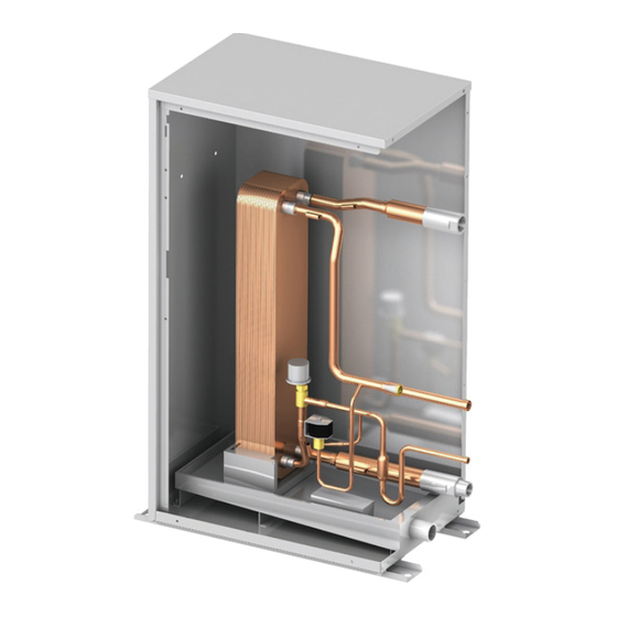
£ £ Components of the Unit [1] Appearance of the Components and Refrigerant Circuit < PWFY-P36NMU-E-BU > Pressure sensor (63LS) Heat exchanger assy Pressure switch (63H1) Thermistor (TH8) Pressure sensor (63HS) Heat exchanger assy Linear expansion valve Thermistor (TH11) Linear expansion valve coil... -
Page 26: Control Box
Solenoid valve coil (SVG) Solenoid valve Check valve (CV2) Solenoid valve coil (SV1) Solenoid valve Solenoid valve coil (SVL) Thermistor (TH22) Thermistor (TH6) [2] Control Box < PWFY-P36NMU-E-BU > Thermistor (THHS) INV board Reactor Noise filter Fuse Terminal block (TB2) Control board... - Page 27 < PWFY-P36, P72NMU-E-AU > Transformer Fuse Control board Terminal block (TB5) Terminal block (TB15) DSA board Terminal block (TB2) < PWFY-P36, P72NMU-E2-AU > Transformer Fuse Control board Terminal block assy (TB5) Terminal block assy (TB15) Fuse DSA board Terminal block assy (TB2) - 24 -...
-
Page 28: Circuit Board
[3] Circuit Board 1. Main board < PWFY-P36NMU-E-BU, PWFY-P36, P72NMU-E/E2-AU > - 25 -... - Page 29 2. Power board < PWFY-P36NMU-E-BU > - 26 -...
- Page 30 3. Noise filter < PWFY-P36NMU-E-BU > CN52C CNAC2 CNAC1 4. DSA < PWFY-P36, P72NMU-E/E2-AU > - 27 -...
-
Page 31: Remote Controller
¢ ¢ Remote Controller [1] Functions and Specifications of MA Remote Controller MA remote controller is connected to each unit. Function/specification MA remote controller Remote controller address setting Not required Indoor/outdoor unit address setting Not required (required only by a system with one outdoor unit) Wiring method Non-polar 2 wires ✻... -
Page 32: Interlocking Setting Via The Ma Remote Controller
[2] Interlocking Setting via the MA Remote Controller 1. Remote controller function selection via the MA remote controller Function selection of remote controller The setting of the following remote controller functions can be changed using the remote controller function selection mode. Change the setting when needed. Item 2 Item 1 Item 3 (Setting content) - Page 33 [3]–3. Mode selection setting Detailed setting (1) Remote controller main/sub setting [3]–1. CHANGE LANGUAGE setting ON/OFF] button D. • To switch the setting, press the [ The language that appears on the dot display can be selected. 1 Main : The controller will be the main controller. •...
-
Page 34: Electrical Wiring Diagram
∞ ∞ Electrical Wiring Diagram [1] PWFY-P36NMU-E-BU - 31 -... -
Page 35: Pwfy-P36, P72Nmu-E/E2-Au
[2] PWFY-P36, P72NMU-E/E2-AU - 32 -... - Page 36 - 33 -...
-
Page 37: Refrigerant Circuit
§ § Refrigerant Circuit [1] Refrigerant Circuit Diagram < PWFY-P36NMU-E-BU > LEV1W LEV2W TH22 Water inlet Brazed screw 63HS 63LS TH11 Water outlet screw Brazed PHEX PHEX TH13 63H1 COMP < PWFY-P36NMU-E-AU > Flow switch Field supply Field supply TH23... -
Page 38: Pump Interlock
Brazed LEV1Wa TH22 Liquid LEV1Wb piping Water inlet Screw Brazed Pump interlock PWFY-P36/P72NMU-E/E2-AU, < PWFY-P36NMU-E-BU > < PWFY-P36/72NMU-E/E2-AU > packaged (Fig.C) Board AC208 - 230V DC30V or less TB141A OUT1 52P or 72P 51P or 71P Fuse Coil of the magnetic contactor for heat source water... -
Page 39: Functions Of Principal Parts
Functions of Principal Parts 1. Unit Symbols Part Notes Usage Specifications Check method (functions) Name Compres- High-pressure shell rotary Adjusts the amount of circulating refrigerant by adjusting the operating compressor frequency based on the operating 20˚C[68˚F] : 0.583Ω pressure data High 63HS 1) Detects high pressure... - Page 40 Symbols Part Notes Usage Specifications Check method (functions) Name PWFY-P36, Solenoid A refrigerant bypass circuit that AC208~230V Continuity check P72NMU- valve Bypass functions to prevent water heat Open when energized with a tester E/E2-AU only solenoid exchanger from icing up during the Closed when not energized valve (defrost) defrost cycle.
-
Page 41: Control
¶ ¶ Control [1] Dip Switch Functions and Their Factory Settings 1. Unit (1) Main board Error history deleted Normal Deleted Keep overwrite protection Reset overwrite protection Resets the pre-error data overwrite protection. *4 Sets the restart interval for the 9 seconds 9 minutes and 59 seconds Before power on... - Page 42 • The amount of subcool is controlled by LEV1W(a,b) based on the differential between liquid refrigerant piping temperature (TH22) and condensing temperature every 1 miniute. • Defrost operation (1) Booster Unit (PWFY-P36NMU-E-BU) It stays opened at (LEV1W = 1400 pulse) during defrost operation (2) HEX Unit (PWFY-P36, 72NMU-E/E2-AU) It depends on inletwater temperature (TH6) as below.
- Page 43 Initial operation mode completed 6. Control box cooling System <PWFY-P36NMU-E-BU> On the PWFY-P36NMU-E-BU model, the cooling fan operates for the period between one minute before compressor startup and one minute after compressor stoppage to prevent INV temperature from rising. 7. Super heat control of the high-side (R134a) of the binary cycle.
-
Page 44: Test Run
Note 1: Refer to the following pages if an error code appears on the remote controller or when the unit malfunctions. 2: The OFF timer will automatically stop the test run after 2 hours. [3] Refrigerant PWFY-P36NMU-E-BU Unit type Refrigerant type R134a 1.1kg... -
Page 45: Symptoms That Do Not Signify Problems
This is caused by the transient instability of the heard from the indoor unit refrigerant flow and is normal. immediately after starting operation. [5] Standard operation data PWFY-P36NMU-E-BU Indoor DB/WB ˚C [˚F] 19.4 [67] / – Outdoor DB/WB ˚C [˚F] 8.3 [47] / 6.1 [43]... -
Page 46: Troubleshooting
ª ª Troubleshooting [1] Check Code List BU: PWFY-P36NMU-E-BU 1. Error Code and Preliminary Error Code List AU: PWFY-P36 , P72NMU-E/E2-AU Error Searched unit Prelimi- (prelim- Error nary inary) Error code definition Notes Code error detail code code 0403 4300... -
Page 47: Responding To Error Display On The Remote Controller
[2] Responding to Error Display on the Remote Controller 1. Error Code 0403 Serial communication error 2. Error definition and error detection method Serial communication error between the control board and the INV board on the compressor. Detail code 01: Between the control board and the INV board 3. - Page 48 1. Error Code 1102 Abnormal discharge air temperature 2. Error definition and error detection method 1) If a discharge temperature of 115 C [239 F] or higher is detected (first detection), units will stop, go into the 3-minute restart delay mode, and automatically restart after three minutes. 2) If a discharge temperature of 115 C [239 F ] or higher is detected again (second detection) within 30 minutes of the first stoppage of the units as described above, units will stop, go into the 3 minute restart delay mode, and automatically restart after three minutes.
- Page 49 1. Error Code 1302 Abnormal high pressure 1 2. Error definition and error detection method 1) If a pressure of 3.23MPa [468 psi ] or higher is detected during operation, units will stop, go into the 3 minute restart delay mode, and automatically restart after three minutes. If a pressure of 3.23MPa [468 psi ] or higher is detected again (second detection) within 30 minutes of the first stoppage of the units, units will stop, go into the 3 minute restart delay mode, and automatically restart after three minutes.
- Page 50 1. Error Code 2000 Pump interlock error (BU only) 2. Error definition and error detection method Preliminary pump interlock error is detected when the pump interlock circuit becomes open while the units are stopped during Thermo-ON. When a preliminary error is detected, units will go into the Thermo-OFF state and into the restart-prevention mode. When the amount of time listed below has elapsed since the time when a given preliminary error was detected, an error code "2000"...
- Page 51 1. Error Code 2135 Water heat exchanger freeze up 2. Error definition and error detection method Both TH22 and TH23 of 1˚C [ 34 ] or below have been detected for three minutes in a mode other than Heating Thermo-ON. Condition 1 If PWFY is running in Heating Thermo-ON mode TH22 of -15˚C or below has been detected for 3 continuous minutes...
- Page 52 1. Error Code 4102 Open phase 2. Error definition and error detection method An open phase of the power supply (L1 phase, L2 phase) was detected at power on. The L2 phase current is outside of the specified range. The open phase of the power supply may not always be detected if a power voltage from another circuit is applied. 3.
- Page 53 Error Code 4115 Power supply signal sync error Error definition and error detection method The frequency cannot be determined when the power is switched on. Cause, check method and remedy Power supply error Check the voltage of the power supply terminal block (TB2).
- Page 54 1. Error Code 4220 Bus voltage error (PAM damage) (Detail code 01) 2. Error definition and error detection method PWM circuit error on the INV board is detected. 3. Cause, check method and remedy (1) INV board failure Replace the INV board. Refer to section - 5 - "Inverter"...
- Page 55 1. Error Code 4230 Heat sink overheat protection 2. Error definition and error detection method When the heatsink temperature (THHS) remains at or above 85˚C is detected. 3. Cause, check method and remedy Checking the fan wiring. Check connectors CN506A and CN506B on the control board. Check the fan wiring for breakage and damage.
- Page 56 1. Error Code 4250 IPM error (Detail code 101) 2. Error definition and error detection method Overcurrent is detected while power module error detection signal is output. 3. Cause, check method and remedy Check the inverter output wiring Check the fan wiring for breakage and damage. for proper connection.
- Page 57 1. Error Code 5102 TH22 temperature sensor failure (BU, AU ) 5103 TH13, TH23 temperature sensor failure (BU, AU) 5104 TH11 temperature sensor failure (BU) 5106 TH6 temperature sensor failure (BU, AU ) 5108 TH8 temperature sensor failure (BU, AU ) 2.
- Page 58 1. Error Code 5110 Heat sink failure 2. Error definition and error detection method When a short or an open of THHS is detected just before or during the inverter operation. 3. Cause, check method and remedy u l i en the unit is put into operation, replace the INV board.
- Page 59 Error Code 5202 Low-pressure sensor fault 2. E rror definition and error detection method When a pressure sensor reading of 4.06 MPa [589 psi] or above is detected, error code "5202" will appear. The unit will continue its operation by using other sensors as a backup. 3.
- Page 60 -1- Troubleshooting according to the remote controller malfunction or the external input error 1. Phenomena Even if the operation button on the remote controller is pressed, the display remains unlit and the unit does not start running.(Power indicator does not appear on the screen.) 2.
- Page 61 . Phenomena hen the remote controller operation S is turned on, the operation status briefly appears on the display, then it goes off, and the display lights out immediately, and the unit stops. 2. Cause 1) The power for the M-NET transmission line is not supplied from the outdoor unit. 2) Short circuit of the transmission line.
- Page 62 1. Phenomena "HO" or "PLEASE WAIT" display on the remote controller does not disappear, and no operation is performed even if the button is pressed. ("HO" or "PLEASE WAIT" display will normally turn off 5 minutes later after the power on.) 2.
-
Page 63: Troubleshooting Principal Parts
[3] T roubleshooting Principal Parts -1- High-Pressure Sensor (63HS) 1. Compare the pressure that is detected by the high pressure sensor, and the high-pressure gauge pressure to check for failure. By configuring the digital display setting switch (SW1) as shown in the figure below, the pressure as measured by the high-pressure sensor appears on the LED1 on the control board. - Page 64 -2- Low-Pressure Sensor (63LS) 1. Compare the pressure that is detected by the low pressure sensor, and the low pressure gauge pressure to check for failure. By configuring the digital display setting switch (SW1) as shown in the figure below, the pressure as measured by the low-pressure sensor appears on the LED1 on the control board.
- Page 65 -3- Solenoid Valve Check whether the output signal from the control board and the operation of the solenoid valve match. Setting the self-diagnosis switch (SW1) as shown in the figure below causes the ON signal of each relay to be output to the LED's.
- Page 66 -4- LEV1W (a, b) LEV1W (a, b) operation LEV are stepping-motor-driven valves that operate by receiving the pulse signals from the indoor and outdoor unit control boards. (1) LEV The valve opening changes according to the number of pulses. 1) Indoor and outdoor unit control boards and the LEV (Indoor unit: Linear expansion valve) Outdoor control board Intermediate connector DC12V...
- Page 67 (2) Judgment methods and possible failure mode Malfunction mode Microcomputer Disconnect the control board connector and connect When the drive circuit has a driver circuit fail- the check LED as shown in the figure below. problem, replace the control board. resistance : 0.25W 1k LED : DC15V 20mA or more When the main power is turned on, the indoor unit cir-...
- Page 68 (3) LEV coil removal procedure Motor Driver Locknut Bellows Valve assembling Refrigerant Circuit Valve body side Orifice Notes on the procedure 1) Do not put undue pressure on the motor. 2) Do not use motors if dropped. 3) Do not remove the cap until immediately before the procedure. 4) Do not wipe off any molybdenum.
- Page 69 Replacement procedure 1) Stop all the indoor and outdoor units. Check that all the units are stopped, and turn off the power to the outdoor unit. 2) Prepare two spanners. Hold the valve body with one spanner and loosen the locknut with another one. Turning the locknut counter-clockwise from motor side view can loosen it.
- Page 70 4) LEV2 he valve opening changes according to the number of pulses. 1) Connections between the control board and LEV2W (outdoor expansion valve) Outdoor control board DC 12V Brown Drive circuit Blue Orange Yellow White 2) Pulse signal output and valve operation Output state Output pulses change in the following orders when the Output...
- Page 71 5) LEV LEV2W) coil removal procedure ) LEV component As shown in the figure, the outdoor LEV is made in such a way that the coils and the body can be separated. Body Coils Stopper Lead wire 2) Removing the coils Fasten the body tightly at the bottom (Part A in the figure) so that the body will not move, then pull out the coils toward the top.If the coils are pulled out without the body gripped, undue force will be applied and the pipe will be bent.
- Page 72 -5- Inverter Replace only the compressor if only the compressor is found to be defective. Replace the defective components if the inverter is found to be defective. If both the compressor and the inverter are found to be defective, replace the defective component(s) of both devices. (1) Inverter-related problems: Troubleshooting and remedies 1) The inverter board has a large-capacity electrolytic capacitor, in which residual voltage remains even after the main power is turned off, posing a risk of electric shock.
- Page 73 u l i Inverter related errors heck the details of the inverter error in the error log at 10 . [1 ] LED 4102, 4115, 4220, 4230, 4250, 5110, 5301, 0403 Monitor Display. Take appropriate measures to the error code and the error details in ac- cordance with 9 .
- Page 74 (2) Inverter output related troubles Terminals on the 1) Overcurrent error Replace the INV board. Check the (4250 Detail code No. 101, 102) inverter board INV board er- Remove the inverter ror detection output cable from circuit. U, V, and W terminals. Operate the units.
- Page 75 (3) Trouble treatment when the main power breaker is tripped [1] Check the breaker capacity. Use of a non-specified break- Replace it with a specified breaker. [2] Perform Meg check between the Zero to several ohm, or Meg Check each part and wiring. terminals on the power terminal failure *Refer to (5) "Simple checking Procedures...
- Page 76 (5) Simple checking procedure for individual components of main inverter circuit Leave the power turned off for 10 minutes, check that the voltage between pins 1 and 3 of CN631 on the control board is 20V or below, and remove the circuit board or the parts from the control box. When any problem is found with the circuit board or other parts, replace them.
-
Page 77: Maintenance
[4] Maintenance 1. Section 1 Recovering and charging refrigerant from the R134a side Before replacing the parts on PWFY-P36NMU-E-BU (compressor, LEV, strainer (ST2), PHEX), be sure to take the following steps. [Recovering the refrigerant] 1. Stop all indoor and outdoor units, and turn off all power supplies to the units. - Page 78 [Replacing the parts on PWFY-P36NMU-E-BU] Recover the refrigerant before replacing the parts. Refer to section 1 "Recovering the refrigerant" for how to recover the refrigerant. 1. Stop all indoor and outdoor units, and turn off all power supplies to the units.
- Page 79 [Replacing the LEV] Replacing LEV1 1. Debraze the parts on the pipe that are indicated in the figure, and replace LEV1. 2. Connect the connector to CNLVC on the circuit board. In the case of PWFY-P72NMU-E/E2-AU, connect the connectors to CNLVB and CNLVC on the circuit board. Replacing LEV2 1.
- Page 80 [Replacing the strainer] 1. Debraze the parts on the pipe that are indicated in the figure. 2. Rebraze the debrazed parts after replacement. Brazed parts [Replacing the solenoid valve] 1. Unscrew the screws. 2. Debraze the parts on the pipe that are indicated in the figure.
- Page 81 [Replacing the check valve] 1. Debraze the parts on the pipe that are indicated in the figure. 2. Rebraze the debrazed parts after replacement. <PWFY-P36/P72NMU-E-AU> <PWFY-P36/P72NMU-E2-AU> Brazed parts (CV1) Brazed parts (CV2) Brazed parts [Replacing the strainer ST3, ST4] 1. Debraze the parts on the pipe that are indicated in the figure.
-
Page 82: Led Display
[ 134] : R134A Model and capacity [A-04] : PWFY-P36NMU-E/E2-AU [A-08] : PWFY-P72NMU-E/E2-AU [b-04] : PWFY-P36NMU-E-BU Communication address [ 01] : Address 1 After the initial settings have been completed, the information on these items can be checked by making the switch setting that corresponds to No. - Page 83 (3) Time data storage function If an error (including a preliminary error) occurs, the error history data and the error detection time are stored into the service memory. The error detection time stored in the service memory and the current time can be seen on the service LED. 1) Use the time displayed on the service LED as a reference.
- Page 84 - 81 -...
- Page 85 - 82 -...
- Page 86 - 83 -...
- Page 87 - 84 -...
- Page 88 - 85 -...
- Page 89 - 86 -...
- Page 90 - 87 -...
- Page 91 - 88 -...
- Page 92 - 89 -...
- Page 93 - 90 -...
- Page 94 - 91 -...
- Page 95 - 92 -...
- Page 96 - 93 -...
- Page 97 - 94 -...
- Page 98 - 95 -...
- Page 99 - 96 -...
- Page 100 - 97 -...
- Page 101 - 98 -...
- Page 102 - 99 -...
- Page 103 - 100 -...
- Page 104 - 101 -...
- Page 105 - 102 -...
Need help?
Do you have a question about the PWFY-P36NMU-E-BU and is the answer not in the manual?
Questions and answers