Table of Contents
Advertisement
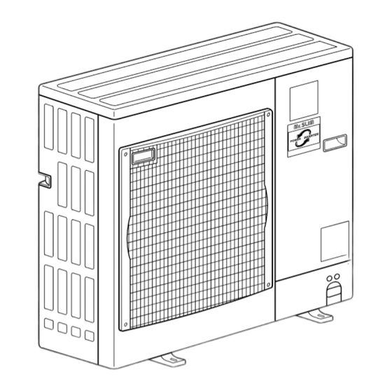
SPLIT-TYPE, HEAT PUMP AIR CONDITIONERS
TECHNICAL & SERVICE MANUAL
R410A
Outdoor unit
[model names]
PUHZ-RP1.6VHA
PUHZ-RP2VHA
PUHZ-RP3VHA
PUHZ-RP4VHA
PUHZ-RP5VHA
PUHZ-RP6VHA
PUHZ-RP2.5VHA
PUHZ-RP3VHA
[Service Ref.]
PUHZ-RP1.6VHA
PUHZ-RP2VHA
PUHZ-RP2.5VHA
PUHZ-RP2.5VHA
PUHZ-RP3VHA
PUHZ-RP3VHA
PUHZ-RP4VHA
PUHZ-RP4VHA
PUHZ-RP5VHA
PUHZ-RP5VHA
PUHZ-RP6VHA
PUHZ-RP6VHA
Model name
indication
REVISED-EDITION-C
Revision:
• PUHZ-RP2.5VHA
PUHZ-RP3VHA
REVISED EDITION-C.
• Please void OC294 REVISED
EDITION-B.
1
1
1
1
1
CONTENTS
1. TECHNICAL CHANGES·································2
2. SAFETY PRECAUTION··································3
4. PART NAMES AND FUNCTIONS ··················7
5. SPECIFICATIONS···········································8
6. DATA ·····························································11
7. OUTLINES AND DIMENSIONS····················13
8. WIRING DIAGRAM ·······································16
9. CONNECTING CABLE ·································18
10. REFRIGERANT SYSTEM DIAGRAM··············19
11. TROUBLESHOOTING···································25
12. DISASSEMBLY PROCEDURE ·····················71
13. PARTS LIST ··················································91
14. OPTIONAL PARTS························Back Cover
2004
No.OC294
,
1
are added in
1
Advertisement
Chapters
Table of Contents

Related Manuals for Mitsubishi PUHZ-RP1.6VHA


Summary of Contents for Mitsubishi PUHZ-RP1.6VHA
-
Page 1: Table Of Contents
SPLIT-TYPE, HEAT PUMP AIR CONDITIONERS 2004 No.OC294 REVISED-EDITION-C TECHNICAL & SERVICE MANUAL R410A Outdoor unit Revision: [model names] [Service Ref.] • PUHZ-RP2.5VHA PUHZ-RP3VHA are added in PUHZ-RP1.6VHA PUHZ-RP1.6VHA REVISED EDITION-C. PUHZ-RP2VHA PUHZ-RP2VHA • Please void OC294 REVISED PUHZ-RP2.5VHA EDITION-B. PUHZ-RP2.5VHA PUHZ-RP2.5VHA PUHZ-RP3VHA PUHZ-RP3VHA PUHZ-RP3VHA... -
Page 2: Technical Changes
TECHNICAL CHANGES PUHZ-RP4VHA PUHZ-RP4VHA PUHZ-RP5VHA PUHZ-RP5VHA PUHZ-RP6VHA PUHZ-RP6VHA 1. Reduced Design Pressure: Design Pressure has been changed from 4.41MPa to 4.15MPa. (High Pressure Switch has been changed.) 2. Partial Change on Refrigerant Circuit: Only 1 distributor is adopted on the Heat Exchanger. (Previously 2) 3. -
Page 3: Safety Precaution
SAFETY PRECAUTION 2-1. CAUTIONS RELATED TO NEW REFRIGERANT Cautions for units utilizing refrigerant R410A Use new refrigerant pipes. Do not use refrigerant other than R410A. In case of using the existing pipes for R22, be careful with If other refrigerant (R22 etc.) is used, chlorine in refrige- the followings. - Page 4 Unit Gravimeter [3] Service tools Use the below service tools as exclusive tools for R410A refrigerant. Specifications Gauge manifold ·Only for R410A ·Use the existing fitting specifications . (UNF1/2) ·Use high-tension side pressure of 5.3MPa·G or over. Charge hose ·Only for R410A ·Use pressure performance of 5.09MPa·G or over.
- Page 5 2-2. Changed point • Precautions when reusing existing R22 refrigerant pipes (1) Flowchart Measure the existing pipe thickness and check for damage. The existing pipe thickness meets speci- The existing pipe thickness does not meet fications and the pipes are not damaged. specifications or the pipes are damaged.
- Page 6 (2) Cautions for refrigerant piping work New refrigerant R410A is adopted for replacement inverter series. Although the refrigerant piping work for R410A is same as for R22, exclusive tools are necessary so as not to mix with different kind of refrigerant. Furthermore as the working pressure of R410A is 1.6 time higher than that of R22, their sizes of flared sections and flare nuts are different.
-
Page 7: Combination Of Indoor And Outdoor Units
PKA-RP OC305 — — — — — · — PCA-RP OC311 PART NAMES AND FUNCTIONS PUHZ-RP1.6VHA PUHZ-RP2.5VHA PUHZ-RP2.5VHA PUHZ-RP2VHA PUHZ-RP3VHA PUHZ-RP3VHA PUHZ-RP4VHA PUHZ-RP4VHA PUHZ-RP5VHA PUHZ-RP5VHA PUHZ-RP6VHA PUHZ-RP6VHA CHARGELESS SYSTEM PRE-CHARGED REFRIGERANT IS SUPPLIED FOR PIPING LENGTH AT SHIPMENT. (Max.30m(PUHZ-RP1.6~RP6)) The refrigerant circuit with LEV(Linear Expansion Valve) and power receiver always control the optimal refrigerant level regardless of the length (30m max. -
Page 8: Specifications
SPECIFICATIONS Service Ref. PUHZ-RP1.6VHA PUHZ-RP2VHA Function Cooling Heating Cooling Heating Single, 50Hz, 220-230-240V Power supply (phase, cycle, voltage) Running current 4.01 4.23 6.16 6.47 Munsell 3Y 7.8/1.1 External finish Refrigerant control Linear Expansion Valve Hermetic Compressor Model SNB130FLBH Motor output... - Page 9 PUHZ-RP2.5VHA PUHZ-RP3VHA PUHZ-RP4VHA Service Ref. PUHZ-RP2.5VHA PUHZ-RP3VHA PUHZ-RP4VHA Function Cooling Heating Cooling Heating Cooling Heating Single, 50Hz, 220-230-240V Power supply (phase, cycle, voltage) Running current 6.61 7.50 8.04 9.74 12.33 13.94 Munsell 3Y 7.8/1.1 External finish Refrigerant control Linear Expansion Valve Hermetic Compressor TNB220FMBH...
- Page 10 PUHZ-RP5VHA PUHZ-RP6VHA Service Ref. PUHZ-RP5VHA PUHZ-RP6VHA Function Cooling Heating Cooling Heating Power supply (phase, cycle, voltage) Single, 50Hz, 220-230-240V Running current 15.80 17.50 20.73 20.37 Munsell 3Y 7.8/1.1 External finish Refrigerant control Linear Expansion Valve Hermetic Compressor Model ANV33FDAMT Motor output Starter type Line start HP switch, LP switch, Discharge thermo...
-
Page 11: Data
DATA 6-1. REFILLING REFRIGERANT CHARGE (R410A : kg) Piping length (one way) Factory Service Ref. charged PUHZ-RP1.6VHA — — PUHZ-RP2VHA — — PUHZ-RP2.5VHA — — PUHZ-RP2.5VHA PUHZ-RP3VHA — — PUHZ-RP3VHA PUHZ-RP4VHA PUHZ-RP5VHA PUHZ-RP6VHA PUHZ-RP4VHA PUHZ-RP5VHA PUHZ-RP6VHA Longer pipe than 30m, additional charge is required. - Page 12 6-3. NOISE CRITERION CURVES MICROPHONE UNIT 1.5m GROUND PUHZ-RP1.6VHA PUHZ-RP2.5VHA SPL(dB) SPL(dB) MODE LINE MODE LINE COOLING COOLING PUHZ-RP2.5VHA PUHZ-RP2VHA HEATING HEATING PUHZ-RP3VHA PUHZ-RP3VHA NC-70 NC-70 NC-60 NC-60 NC-50 NC-50 NC-40 NC-40 NC-30 NC-30 APPROXIMATE APPROXIMATE THRESHOLD OF THRESHOLD OF...
-
Page 13: Outlines And Dimensions
OUTLINES AND DIMENSIONS PUHZ-RP1.6VHA Unit : mm PUHZ-RP2VHA [33 drain hole 347.5 Air intake Air intake [33 drain hole 45.4 Service panel 4-10 o 21 oval hole (M10 foundation bolt) Service panel for charge plug Air discharge Handle for Connection for... -
Page 14: Puhz-Rp2.5Vha
PUHZ-RP2.5VHA Unit : mm PUHZ-RP2.5VHA PUHZ-RP3VHA PUHZ-RP3VHA... - Page 15 PUHZ-RP4VHA Unit : mm PUHZ-RP4VHA PUHZ-RP5VHA PUHZ-RP5VHA PUHZ-RP6VHA PUHZ-RP6VHA...
-
Page 16: Wiring Diagram
WIRING DIAGRAM PUHZ-RP1.6VHA PUHZ-RP2VHA PUHZ-RP2.5VHA PUHZ-RP2.5VHA PUHZ-RP3VHA PUHZ-RP3VHA W1 MODEL SELECT MODELS MODELS 1.6V 2.5V 2 3 4 5 6 2 3 4 5 6 2 3 4 5 6 2 3 4 5 6 W2 Only PUHZ-RP2.5, 3VHA. - Page 17 PUHZ-RP4VHA PUHZ-RP4VHA PUHZ-RP5VHA PUHZ-RP5VHA PUHZ-RP6VHA PUHZ-RP6VHA Only PUHZ-RP4VHA PUHZ-RP5VHA PUHZ-RP6VHA W1 MODEL SELECT MODELS 2 3 4 5 6 2 3 4 5 6 2 3 4 5 6...
-
Page 18: Connecting Cable
CONNECTING CABLE For 220-240V 50Hz The cable shall not be lighter than design 245 IEC or 227 IEC. The cable length may vary depending on the condition of installation, humidity or materials, etc. Wire size Cross section Number Polarity L(m) of cable of wires Round... -
Page 19: Refrigerant System Diagram
REFRIGERANT SYSTEM DIAGRAM PUHZ-RP1.6VHA Thermistor TH7 PUHZ-RP2VHA (Outdoor) Heat exchanger Stop valve Thermistor TH6 Charge plug (with service port) Solenoid valve (Outdoor 2-phase pipe) (Four-way valve) Refrigerant GAS pipe connection(1/2F) Strainer Thermistor TH3 (Outdoor pipe) Muffler Distributor High pressure switch 63H... - Page 20 PUHZ-RP4VHA PUHZ-RP5VHA Thermistor TH7 PUHZ-RP6VHA (Outdoor) Heat exchanger Thermistor TH6 Ball valve Solenoid valve Strainer (Outdoor 2-phase pipe) (Four-way valve) Refrigerant GAS pipe connection(5/8F) Thermistor TH3 Charge plug (Outdoor pipe) (High pressure) Muffler Charge plug (Low pressure) Distributor Low pressure switch 63L High pressure Strainer...
- Page 21 Applicable extension pipe for each model The height difference between indoor and outdoor unit should be kept within 30 m for all models. (1) 1:1 system (a) Maximum pipe length <Table 1> Pipe length for 1:1 system Liquid [6.35 [9.52 [12.7 pipe Thick-...
-
Page 22: Heating
(c) Capacity correction Cooling and heating capacity is lowered according to pipe length. Capacity can be obtained by referring to the capacity curves below. When the diameter of gas pipe is one size smaller than standard diameter, cooling capacity is lowered com- paring to the standard diameter. - Page 23 3 3 Capacity curve for PUHZ-RP2.5, 3 models <When gas pipe is one size smaller than standard size> Heating RP2.5, RP3 Cooling RP2.5 Cooling RP3 Corrected pipe length 4 4 When gas pipe is one size larger than standard size for PUHZ-RP4, 5 and 6. 1 Capacity can be obtained by referring to capacity curves of standard size.
- Page 24 1. Refrigerant collecting (pump down) Perform the following procedures to collect the refrigerant when moving the indoor unit or the outdoor unit. 1Before collecting the refrigerant, first make sure that the all of the SW5 DIP switches for function changes on the control board of the outdoor unit are set to OFF.
-
Page 25: Troubleshooting
TROUBLESHOOTING 11-1. TROUBLESHOOTING <Error code display by self-diagnosis and actions to be taken for service (summary)> Present and past error codes are logged and displayed on the wired remote controller and control board of outdoor unit. Actions to be taken for service, which depends on whether or not the inferior phenomenon is reoccurring at service, are sum- marized in the table below. - Page 26 11-2. Check point under test run (MA remote controller) (1) Before test run • After installation of indoor and outdoor units, piping work and electric wiring work, re-check that there is no refrigerant leak- age, loosened connections and incorrect polarity. •...
- Page 27 wPress the remote controller’s CHECK button twice to perform self-diagnosis. See the table below for the contents of LCD display. Contents of inferior phenomena Contents of inferior phenomena Abnormality of room temperature thermistor Malfunction outdoor unit U1~UP Abnormality of pipe temperature thermistor/Liquid F3~F9 Malfunction outdoor unit Abnormality of drain sensor...
- Page 28 11-3. Malfunction-diagnosis method by remote controller 11-3-1. Error history of unit (1) Wired remote controller <In case of trouble during operation> Setting number If there is a trouble on air conditioner, both indoor unit and out- Refrigerant address Mode number door unit will stop and digital display shows what was wrong.
- Page 29 4 To cancel self-diagnosis There are following two methods to cancel self-diagnosis: Press the H “CHECK” button twice within three seconds. Self-diagnosis is cancelled and the display screen will return to the status before self-diagnosis. Press the I “ON/OFF” button. Self-diagnosis is cancelled and indoor unit will stop.
- Page 30 (2) Digital wireless remote controller <In case of trouble during operation> When a malfunction occurs to air conditioner, both indoor unit and outdoor unit will stop and operation lamp blinks to inform unusual stop. < Malfunction-diagnosis method at maintenance service> [Procedure] 1.
- Page 31 11-3-2. Wired Remote controller Diagnosis If operation can not be carried out from remote controller, try remote controller diagnosis with following process. 1 First, check the electricity current marker. When correct voltage (DC12V) is not supplied to remote controller, the electricity current marker is put out. If the electricity current marker is not lighted, check the remote controller wiring and the indoor units.
- Page 32 11-4. SELF-DIAGNOSIS ACTION TABLE (Note 1) Refer to indoor unit section for code P and code E. <Abnormalities detected when the power is put on> Error Code Meaning of error code and detection method Judgment and action Case 1 No voltage is supplied to terminal 1 Check following items.
-
Page 33: Noise
Error Code Meaning of error code and detection method Case Judgment and action 1 Contact failure or mis-wiring of 1 Check disconnection or looseness or polarity Indoor/outdoor unit connector indoor/outdoor unit connecting of indoor/outdoor unit connecting wire of mis-wiring, excessive number of units indoor and outdoor units. - Page 34 <Abnormalities detected while unit is operating> <Abnormalities detected while unit is operating> Error Code Meaning of error code and detection method Judgment and action Case 1 Short cycle of indoor unit 1~6Check indoor unit and repair defectives. Abnormal high pressure (High-pressure 2 Clogged filter of indoor unit switch 63H worked) Abnormal if high-pressure switch 63H...
- Page 35 Error Code Meaning of error code and detection method Judgment and action Case Open/short circuit of discharge 1 Disconnection or contact 1 Check connection of connector (TH4) on the temperature thermistor (TH4) failure of connector (TH4) on outdoor controller circuit board. Check breaking of the lead wire for the outdoor controller circuit Abnormal if open (3: or less) or short...
- Page 36 Error Code Meaning of error code and detection method Judgment and action Case Abnormality such as overvoltage or 1 Decrease of power supply voltage 1 Check the facility of power supply. voltage shortage and abnormal 2 Disconnection of compressor 2 Correct the wiring (U•V•W phase) to compressor. synchronous signal to main circuit wiring Refer to page 52 and 53.
-
Page 37: Noise
Error Code Meaning of error code and detection method Judgment and action Case 1 Defective communication cir- 1~3 Diagnose remote controller. Remote controller communication error (Signal receiving error) cuit of remote controller Take actions as follows according to (1) Abnormal if any signal from IC of refrig- 2 Defective communication cir- diagnosis result. -
Page 38: Noise
Error Code Meaning of error code and detection method Judgment and action Case 1 Slight temperature difference Abnormality of pipe temperature Check pipe <liquid or condenser / <Cooling mode> between indoor room evaporator> temperature with room Detected as abnormal when the pipe tem- temperature and pipe <liquid temperature display on remote perature is not in the cooling range 3 min-... -
Page 39: Noise
Error Code Meaning of error code and detection method Case Judgment and action 1 Data of transmission proces- Communication error with communica- Shut of the power supply of outdoor unit and tion processor sor or unit processor is not indoor unit and FRESH MASTER or LOSSNAY Defective communication between unit at the same time for two minutes or more, and transmitted normally because... - Page 40 From the previous page. Error Code Meaning of error code and detection method Case Judgment and action 1 During group operation with Same as mentioned in “A7” of the previous 4. If displayed address or attribute is remote controller, indoor unit of multi- refrigerant page.
-
Page 41: Noise
Error Code Meaning of error code and detection method Case Judgment and action 1 Transmitting condition is 1 Check transmission wave form or noise on M-NET•NO RESPONSE Abnormal if a massage was transmitted repeated fault because of transmission wire. noise and the like. and there were reply (ACK) that massage 2 Shut off the power supply of outdoor unit and 2 Extension of transmission wire... - Page 42 Phenomena Factor Countermeasure 4. Even controlling by the wireless 1The pair number settings of the wireless remote 1Check the pair number settings. remote controller no beep is heard controller and indoor controller board are mis- and the unit does not start operat- matched.
- Page 43 11-6. HOW TO CHECK THE PARTS PUHZ-RP1.6HA PUHZ-RP2VHA PUHZ-RP2.5VHA PUHZ-RP2.5VHA PUHZ-RP3VHA PUHZ-RP3VHA PUHZ-RP4VHA PUHZ-RP4VHA PUHZ-RP5VHA PUHZ-RP5VHA PUHZ-RP6VHA PUHZ-RP6VHA Parts name Check points Disconnect the connector then measure the resistance using a tester. Thermistor (TH3) (Surrounding temperature 10:~30:) <Outdoor pipe> Normal Abnormal Thermistor (TH4) <Discharge>...
- Page 44 11-7. HOW TO CHECK THE COMPONENTS <Thermistor feature chart> Low temperature thermistors • Thermistor <Outdoor pipe> (TH3) • Thermistor <Outdoor 2-phase pipe> (TH6) • Thermistor <Outdoor> (TH7) Thermistor R0 = 15k' ± 3% B constant = 3480K ± 2% =15exp{3480( 273+t – 273 )} 15k' 4.3k' 9.6k'...
-
Page 45: Noise
Linear expansion valve (1) Operation summary of the linear expansion valve. • Linear expansion valve open/close through stepping motor after receiving the pulse signal from the outdoor controller board. • Valve position can be changed in proportion to the number of pulse signal. <Connection between the indoor controller board and the linear expansion valve>... - Page 46 (3) How to attach and detach the coil of linear expansion valve <Composition> Linear expansion valve is separable into the main body and the coil as shown in the diagram below. Main body Coil Lead wire Stopper <How to detach the coil> Hold the lower part of the main body (shown as A) firmly so that the main body does not move and detach the coil by pulling it upward.
-
Page 47: Heating
11-8. EMERGENCY OPERATION (1) When the error codes shown below are displayed on outdoor unit or microcomputer for wired remote controller or indoor unit has a failure, but no other problems are found, emergency operation will be available by setting the emergency opera- tion switch (SWE) to ON and short-circuiting the connector (CN31) on outdoor controller board. -
Page 48: Noise
11-9. TEST POINT DIAGRAM FAN12 FAN22 • (FAN22 is only for RP4-6VHA.) Outdoor controller circuit board Connect to fan motor (MF) PUHZ-RP1.6VHA PUHZ-RP4VHA (Detection of position) PUHZ-RP2VHA PUHZ-RP4VHA 1 to 5 5V DC pulse PUHZ-RP2.5VHA PUHZ-RP5VHA 2 to 5 (Detected while the 3 to 5 PUHZ-RP2.5VHA... -
Page 49: Noise
Outdoor noise filter circuit board PUHZ-RP1.6VHA PUHZ-RP2VHA LI, NI Voltage of 220-240V AC is input. Connect to the earth (Connect to the terminal block(TB1)) CNAC1, CNAC2 220-240V AC (Connect to the Primary current outdoor controller (Connect to the circuit board... -
Page 50: Noise
Outdoor noise filter circuit board PUHZ-RP2.5VHA PUHZ-RP2.5VHA PUHZ-RP3VHA LI, NI PUHZ-RP3VHA Voltage of 220-240V AC is input. Connect to the earth (Connect to the terminal block(TB1)) CNAC1, CNAC2 220-240V AC (Connect to the outdoor controller circuit board (CNAC)) Primary current (Connect to the outdoor power circuit board... -
Page 51: Noise
Outdoor noise filter circuit board PUHZ-RP4VHA PUHZ-RP4VHA LO, NO Voltage of 220-240V AC is output PUHZ-RP5VHA (Connect to the outdoor power PUHZ-RP5VHA circuit board (SC-R, SC-S)) PUHZ-RP6VHA PUHZ-RP6VHA CNAC1, CNAC2 220-240V AC (Connect to the outdoor controller circuit board (CNAC)) Primary current (Connect to the outdoor power... -
Page 52: Noise
W Usually, they are in a state of being short-circuited if they are broken. Outdoor Power circuit board Measure the resistance in the following points (connectors, etc.). If they PUHZ-RP1.6VHA are short-circuited, it means that they are broken. PUHZ-RP2VHA 1. Check of DIP-IPM PUHZ-RP2.5VHA... -
Page 53: Noise
Brief Check of POWER MODULE W Usually, they are in a state of being short-circuited if they are broken. Outdoor Power circuit board Measure the resistance in the following points (connectors, etc.). PUHZ-RP4VHA If they are short-circuited, it means that they are broken. 1. - Page 54 11-10. FUNCTION OF SWITCHES, CONNECTORS AND JUMPERS (1) Function of switches Type Action by the switch operation Function Effective timing Switch switch When compressor is working Compulsory defrosting Start Normal in heating operation. w Abnormal history clear Clear Normal off or operating 1 2 3 4 5 6 1 2 3 4 5 6...
- Page 55 Effective timing Short Open Connector CN31 Emergency operation Start Normal When power supply ON SW6-1 (J1) :ON(Short) :OFF(Open) SW6-2 SW6(JP) Model (J2) PUHZ-RP1.6VHA SW6-3 PUHZ-RP2VHA (J3) Capacity settings PUHZ-RP2.5VHA SW6-4 PUHZ-RP3VHA Jumper (J4) PUHZ-RP4VHA SW6-5 PUHZ-RP5VHA (J5) PUHZ-RP6VHA SW6-6 (J6)
-
Page 56: Noise
<Display function of inspection for outdoor unit> The blinking patterns of both LED1(green) and LED2(red) indicate the types of abnormality when it occurs. Types of abnormality can be indicated in details by connecting an optional part ‘A-Control Service Tool (PAC-SK52ST)’ to connector CNM on outdoor controller board. - Page 57 Indication Error Outdoor controller board Error Detailed Contents Inspection method code reference LED1 (Green) LED2 (Red) page 1Check if stop valves are open. 3 blinking 1 blinking P.34 Abnormality of shell thermostat 2Check if connectors (TH4, LEV-A, and LEV-B) on outdoor controller board are not and discharging temperature (TH4) disconnected.
- Page 58 <Outdoor unit operation monitor function> [When option part ‘A-Control Service Tool(PAC-SK52ST)’ is connected to outdoor controller board(CNM)] Digital indicator LED1 displays 2 digit number or code to inform operation condition and the meaning of error code by controlling DIP SW2 on ‘A-Control Service Tool’. Operation indicator SW2 : Indicator change of self diagnosis SW2 setting...
- Page 59 SW2 setting Display detail Explanation for display Unit Pipe temperature / Liquid(TH3) – 40~90 – 40~90 (When the coil thermistor detects 0: or below, “–” and temperature are displayed by turns.) (Example) When -10:; 2 3 4 5 6 0.5 secs. 0.5secs.
- Page 60 SW2 setting Display detail Explanation for display Unit Pipe temperature / Liquid(TH3) on error – 40~90 occurring (When the coil thermistor detects 0: or below, “–” – 40~90 and temperature are displayed by turns.) (Example) When –15:; 0.5 secs. 0.5secs. 2 secs.
- Page 61 SW2 setting Display detail Explanation for display Unit The number of connected indoor units (The number of connected indoor units are dis- played.) Unit 2 3 4 5 6 Capacity setting display Displayed as an outdoor capacity code. Capacity Code Capacity Code RP1.6V...
- Page 62 SW2 setting Display detail Explanation for display Unit Indoor setting temperature 17~30 17~30 2 3 4 5 6 Outdoor pipe temperature / Cond./ -39~88 Eva. (TH6) (When the temperature is 0: or less, “–” and -39~88 temperature are displayed by turns.) 2 3 4 5 6 Outdoor outside temperature (TH7) -39~88...
- Page 63 SW2 setting Display detail Explanation for display Unit 0~100 Capacity save (When the capacity is 100% hundreds digit, tens digit 0~255 and ones digit are displayed by turns.) When air conditioner is connected to (Example) When 100%; M-NET and capacity save mode is 0.5 secs.
- Page 64 SW2 setting Display detail Explanation for display Unit 0~480 LEV-A opening pulse on error occurring (When it is 100 pulse or more, hundreds digit, tens 0~480 digit and ones digit are displayed by turns.) (Example) When 130 pulse; Pulse 0.5 secs. 0.5secs.
-
Page 65: Heating
SW2 setting Display detail Explanation for display Unit 0~255 Discharge super heat on error occurring (When the temperature is 100°C or more, hundreds digit, tens digit and ones digit are displayed by 0~255 turns.) Cooling = TH4-TH6 (Example) When 150°C; 0.5 secs. - Page 66 11-11. SELECTING FUNCTIONS USING THE REMOTE CONTROLLER Each function can be set according to necessity using the remote controller. The setting of function for each unit can only be done by the remote controller. Select function available from the table 1. <Table 1>...
-
Page 67: Operating Instructions
11-11-1. Selecting functions using the wired remote controller [Flow of function selection procedure] The flow of function selection procedure is shown below. The flow is described in case of setting indoor temperature detecting shown in table 1 on the preceding page. Refer to procedure 1 to 0 when actually setting functions. Wired type Selecting functions using the wired remote controller Mode number... - Page 68 4 4 Setting the indoor unit number Press C (TIMER SET) button to select the unit Press D(CLOCK ON OFF) and [--] will start to flash in the unit number from 00, 01, 02, 03, 04, and AL. number display (4) . FUNCTION FUNCTION •...
- Page 69 8 8 Registering the settings from steps 3 3 to 7 7 into memory The mode and setting numbers (1)(2) will start to flash when the MODE button E is pressed and registration will begin. The numbers are set when the flashing stays lit. FUNCTION FUNCTION WIf [---] appears in the room temperature display as the mode/setting number, or if a flashing [88] display appears, a transmis-...
- Page 70 11-11-2. Selecting functions using the wireless remote controller (Type C) Functions can be selected with the wireless remote controller. Function selection using wireless remote controller is available only for refriger- ant system with wireless function. Refrigerant address cannot be specified by the wireless remote controller. [Flow of function selection procedure] The flow of the function selection procedure is shown below.
-
Page 71: Disassembly Procedure
DISASSEMBLY PROCEDURE PUHZ-RP1.6VHA PUHZ-RP2VHA OPERATING PROCEDURE PHOTOS Photo 1 1. Removing the top panel, service panel, front panel and Top panel Top panel back panel fixing screws (1) Remove the top panel fixing screws (4 10), one from the right and two from the eft side, and detach the top panel. - Page 72 OPERATING PROCEDURE PHOTOS 3. Removing the electrical parts box Photo 5 (1) Remove the service panel. (See photo 2.) (2) Remove the top panel. (See photo 1.) Controller circuit Electrical parts box (3) Remove the front panel. (See photo 1.) board (C.B.) (4) Disconnect the indoor/outdoor connecting wire from Terminal...
- Page 73 OPERATING PROCEDURE PHOTOS 5. Removing the thermistor <Outdoor> (TH7) Photo 7 Thermistor <Outdoor> (1) Remove the service panel. (See figure 1.) Electrical parts box (TH7) (2) Remove the top panel. (See figure 1.) (3) Disconnect the connector TH7 (red) on the controller circuit board in the electrical parts box.
- Page 74 OPERATING PROCEDURE PHOTOS 8. Removing the four-way valve Photo 10 (1) Remove the service panel. (See photo 2.) (2) Remove the top panel. (See photo 1.) (3) Remove the front panel. (See photo 1.) (4) Remove the back panel. (See photo 1.) (5) Remove the electrical parts box.
- Page 75 OPERATING PROCEDURE PHOTOS 12. Removing the motor for compressor (MC) Photo 13 (1) Remove the service panel. (See photo 2.) (2) Remove the top panel. (See photo 1.) (3) Remove the front panel. (See photo 1.) (4) Remove the back panel. (See photo 1.) (5) Remove the electrical parts box.
- Page 76 PUHZ-RP2.5VHA PUHZ-RP2.5VHA PUHZ-RP3VHA PUHZ-RP3VHA OPERATING PROCEDURE PHOTOS & ILLUSTRATION 1. Removing the service panel and top panel Top panel fixing screws Figure 1 Top panel (1) Remove 3 service panel fixing screws (5 10) and slide the hook on the right downward to remove the service panel.
- Page 77 OPERATING PROCEDURE PHOTOS 4. Removing the thermistor <Outdoor 2-phase pipe> (TH6) Photo 4 Thermistor (1) Remove the service panel. (See figure 1.) <Outdoor 2-phase pipe> Electrical (2) Remove the top panel. (See figure 1.) (TH6) Controller parts box (3) Disconnect the connectors, TH6 and TH7 (red), on the circuit board controller circuit board in the electrical parts box.
- Page 78 OPERATING PROCEDURE PHOTOS 7. Removing the solenoid valve coil <Four-way valve> (21S4), Photo 7 linear expansion valve coil (LEV(A), LEV(B)) and solenoid valve coil <Bypass valve> (SV) Linear expansion Linear expansion (1) Remove the service panel. (See figure 1.) valve coil (LEV B) valve coil (LEV A) (2) Remove the top panel.
- Page 79 OPERATING PROCEDURE PHOTOS 10. Removing the bypass valve Photo 9 (1) Remove the service panel. (See figure 1.) Solenoid valve coil Linear expansion Linear expansion (2) Remove the top panel. (See figure 1.) <Bypass valve> valve coil (LEV B) valve coil (LEV A) (3) Remove the electrical parts box.
- Page 80 OPERATING PROCEDURE PHOTOS 13. Removing the motor for compressor (MC) Photo 12 (1) Remove the service panel. (See figure 1.) (2) Remove the top panel. (See figure 1.) (3) Remove 2 front cover panel fixing screws (5 10) and remove the front cover panel. (See photo 3.) (4) Remove 2 back cover panel fixing screws (5 10) and remove the back cover panel.
- Page 81 PUHZ-RP4VHA PUHZ-RP5VHA PUHZ-RP6VHA OPERATING PROCEDURE PHOTOS & ILLUSTRATION 1. Removing the service panel and top panel Top panel fixing screws Top panel Figure 1 (1) Remove 3 service panel fixing screws (5 10) and slide the hook on the right downward to remove the service Service panel panel.
- Page 82 OPERATING PROCEDURE PHOTOS 4. Removing the thermistor <Outdoor 2-phase pipe> (TH6) Photo 4 Thermistor (1) Remove the service panel. (See figure 1.) <Outdoor 2-phase pipe> Electrical (2) Remove the top panel. (See figure 1.) Controller parts box (TH6) circuit board (3) Disconnect the connectors, TH6 and TH7 (red), on the (C.B.) controller circuit board in the electrical parts box.
- Page 83 OPERATING PROCEDURE PHOTOS 7. Removing the solenoid valve coil <Four-way valve> (21S4), Photo 7 Linear expansion valve coil (LEV A) and linear expansion valve coil (LEV(A), LEV(B)) Solenoid (1) Remove the service panel. (See figure 1.) valve coil <Four-way valve> (2) Remove the top panel.
- Page 84 OPERATING PROCEDURE PHOTOS 10. Removing solenoid valve coil <Bypass valve> (SV) and Photo 9 Solenoid valve coil bypass valve <Bypass valve> (1) Remove the service panel. (See figure 1.) fixing screw (2) Remove the top panel. (See figure 1.) (3) Remove 3 right side panel fixing screws (5 10) in the rear of the unit and remove the right side panel.
- Page 85 OPERATING PROCEDURE PHOTOS 13. Removing the motor for compressor (MC) Photo 12 (1) Remove the service panel. (See figure 1.) (2) Remove the top panel. (See figure 1.) (3) Remove 2 front cover panel fixing screws (5 10) and Power remove the front cover panel.
- Page 86 PUHZ-RP4VHA PUHZ-RP5VHA PUHZ-RP6VHA OPERATING PROCEDURE PHOTOS & ILLUSTRATION 1. Removing the service panel and top panel Top panel fixing screws Top panel Figure 1 (1) Remove 3 service panel fixing screws (5 10) and slide the hook on the right downward to remove the service Service panel panel.
- Page 87 OPERATING PROCEDURE PHOTOS 4. Removing the thermistor <Outdoor 2-phase pipe> (TH6) Photo 4 Thermistor (1) Remove the service panel. (See figure 1.) <Outdoor 2-phase pipe> Electrical (2) Remove the top panel. (See figure 1.) Controller parts box (TH6) circuit board (3) Disconnect the connectors, TH6 and TH7 (red), on the (C.B.) controller circuit board in the electrical parts box.
- Page 88 OPERATING PROCEDURE PHOTOS 7. Removing the solenoid valve coil <Four-way valve> (21S4), Photo 7 and linear expansion valve coil (LEV(A), LEV(B)) (1) Remove the service panel. (See figure 1.) Linear expansion (2) Remove the top panel. (See figure 1.) Solenoid valve coil valve coil (LEV A) <Four-way valve>...
- Page 89 OPERATING PROCEDURE PHOTOS 10. Removing solenoid valve coil <Bypass valve> (SV) and Photo 9 Solenoid valve coil bypass valve <Bypass valve> (1) Remove the service panel. (See figure 1.) fixing screw (2) Remove the top panel. (See figure 1.) (3) Remove 3 right side panel fixing screws (5 10) in the rear of the unit and remove the right side panel.
- Page 90 OPERATING PROCEDURE PHOTOS 13. Removing the motor for compressor (MC) Photo 12 (1) Remove the service panel. (See figure 1.) (2) Remove the top panel. (See figure 1.) (3) Remove 2 front cover panel fixing screws (5 10) and remove the front cover panel. (See photo 3.) (4) Remove 2 back cover panel fixing screws (5 10) and Valve bed...
-
Page 91: Parts List
PARTS LIST STRUCTURAL PARTS PUHZ-RP1.6VHA PUHZ-RP2VHA ty/set Price Recom- Wining Remarks Part No. Part Name Specification Diagram mended (Drawing No.) PUHZ-RP1.6VHA Symbol Unit Amount PUHZ-RP2VHA R01 E10 691 GRILLE R01 E02 668 FRONT PANEL R01 E15 686 BASE ASSY (SU00B229G35) —... - Page 92 COVER PANEL (FRONT) R01 E01 658 COVER PANEL (REAR) R01 E03 661 SIDE PANEL (R) T7W E02 668 SERVICE PANEL (DG79R130H01) — LABEL (MITSUBISHI) — LABEL (INVERTER) (BK79C208G02) R01 E00 698 REAR GUARD R01 E04 641 TOP PANEL R01 E00 655...
- Page 93 R01 E00 658 COVER PANEL (FRONT) R01 E01 658 COVER PANEL (REAR) R01 E04 661 SIDE PANEL (R) T7W E03 668 SERVICE PANEL — LABEL (MITSUBISHI) (DG79R130H01) — LABEL (INVERTER) (BK79C208G02) R01 E01 698 REAR GUARD R01 E04 641 TOP PANEL...
- Page 94 FUNCTIONAL PARTS PUHZ-RP1.6VHA PUHZ-RP2VHA FUSE...
- Page 95 Part numbers that is circled is not shown in the figure. ty/set Price Wining Recom- Remarks Specification Part No. Part Name Diagram mended PUHZ-RP1.6VHA (Drawing No.) Symbol Unit Amount PUHZ-RP2VHA R01 E30 221 FAN MOTOR R01 E02 115 PROPELLER R01 E04 097 R01 E09 467...
- Page 96 FUNCTIONAL PARTS PUHZ-RP2.5VHA PUHZ-RP2.5VHA FUSE PUHZ-RP3VHA PUHZ-RP3VHA...
- Page 97 ty/set Price Wining Recom- PUHZ-RP Remarks Part No. Part Name Specification Diagram mended (Drawing No.) Symbol Unit Amount VHA VHA VHA VHA R01 E28 221 FAN MOTOR R01 E01 115 PROPELLER R01 E02 097 (BK00B055G19) — ELECTRICAL PARTS BOX T7W E00 242 SOLENOID VALVE COIL <BYPASS VALVE>...
- Page 98 FUNCTIONAL PARTS PUHZ-RP4VHA PUHZ-RP5VHA PUHZ-RP6VHA FUSE...
- Page 99 Part numbers that is circled is not shown in the figure. ty/set Price Wining PUHZ-RP Recom- Remarks Part No. Part Name Specification Diagram mended (Drawing No.) Symbol Unit Amount R01 E29 221 FAN MOTOR MF1,2 R01 E01 115 PROPELLER R01 E02 097 R01 E46 408 HEAT EXCHANGER (BK00B055G18)
- Page 100 FUNCTIONAL PARTS PUHZ-RP4VHA PUHZ-RP5VHA PUHZ-RP6VHA...
- Page 101 Part numbers that are circled are not shown in the figures. ty/set Price Wining PUHZ-RP Recom- Remarks Part No. Part Name Specification Diagram mended (Drawing No.) Symbol Unit Amount R01 E29 221 FAN MOTOR MF1,2 R01 E01 115 PROPELLER R01 E02 097 R01 E58 408 HEAT EXCHANGER T7W A01 242...
-
Page 102: Optional Parts
Applied models PUHZ-RP3, 4, 5, 6VHA PUHZ-RP1.6, 2, 2.5, 3, 4, 5, 6VHA HEAD OFFICE : MITSUBISHI DENKI BLDG., 2-2-3, MARUNOUCHI, CHIYODA-KU TOKYO 100-8310, JAPAN cCopyright 2003 MITSUBISHI ELECTRIC ENGINEERING CO., LTD. Distributed in Oct. 2004 No.OC294 REVISED EDITION-C PDF 9 Distributed in Jun.
Need help?
Do you have a question about the PUHZ-RP1.6VHA and is the answer not in the manual?
Questions and answers