
Related Manuals for Grundfos MP 1 / Redi-Flo2


Summary of Contents for Grundfos MP 1 / Redi-Flo2
- Page 1 Submersible pump Grundfos MP 1 / Redi-Flo2 User manual Meet the difference Eijkelkamp Soil & Water +31 313 880 200 P.O. Box 4, 6987 ZG Giesbeek, info@eijkelkamp.com M-1227E © 2017-05 the Netherlands www.eijkelkamp.com...
-
Page 2: Table Of Contents
Setting of pump performance ........................... 10 8.2.2 Minimum flow ..............................10 8.2.3 After use ................................10 8.3 Performance curves MP 1 / Redi-Flo2 pump ....................... 10 9. Maintenance and service ..............................11 9.1 Maintenance ..................................11 9.2 Service ....................................11 10. Dismantling and assembly ..............................12 10.1 Description and overview of the MP 1/Redi-Flo2 sampling pump system .............. -
Page 3: Information On This Manual
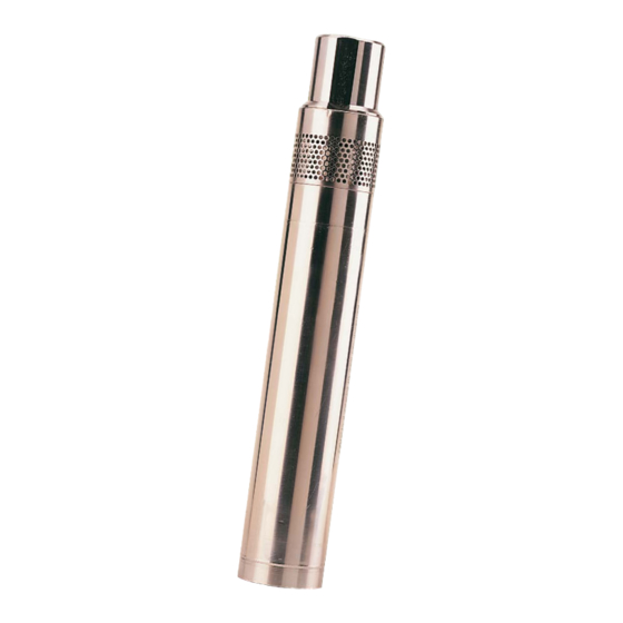
The Teflon power cable is available in different lengths. Applications The Grundfos MP 1/Redi-Flo2 pump is designed for the purging and sampling of contaminated water. The maximum sand content of the water must not exceed 50 g/m . A larger sand content will reduce the life of the service parts and increase the risk of blocking of the pump. -
Page 4: Technical Specifications
The MP 1/Redi-Flo2 pump is not designed for continuous operation like for instance remedial pumping. Continuous operation may reduce the life of the pump. Technical specifications Marking: The MP 1/Redi-Flo2 sampling pump system is CE-marked. Submersible pump Grundfos MP 1/Redi-Flo2: Power input: 1.3 kW Voltage: 3 x 220 V, 400 Hz Maximum current: 5.5 A... -
Page 5: Safety
Safety Safety precautions During handling, operation, storage and transportation, the environmental regulations covering the handling of hazardous material must be observed. When the pump is taken out of operation, care must be taken to ensure that the pump contains no hazardous material that might be injurious to human health or to the environment. -
Page 6: Storage
Storage The pumping system should be stored in a clean and dry area. 4.2.1 MP 1/Redi-Flo2 pump Storage temperature: –20 °C to +50 °C. If the pump has to be stored after use, it must be cleaned thoroughly before storing. See section 9. Maintenance and service. -
Page 7: Checking Of Liquid In Motor
Checking of liquid in motor The level of the liquid in the motor should be checked before the pump is installed. 1. Place the pump and motor in a vertical position with the discharge port pointing downwards (i.e. the bottom of the motor is uppermost), and remove the filling screw. See fig. 4. 2. If the water stands up to the edge of the threaded hole, no filling is required. If not, fill demineralised water into the motor. -
Page 8: Converter
Converter Position of the converter Place the converter with cabinet (case) in such a way that water cannot enter into the cabinet. Do not close the cabinet during operation. The converter must be installed vertically to ensure free air circulation around the unit. See fig. 7. -
Page 9: Electrical Connection
Electrical connection Before starting work on the pump, make sure that the electricity supply has been switched off and that it cannot be accidentally switched on. Use the separate manual (M122746) on both converters for instructions on connecting the converter. Connection of the MP 1/Redi-Flo2 pump to the converter Connect the power (motor) cable from the pump with the power/motor cable of the converter. -
Page 10: Operation
After use After use, switch off the electricity supply to the converter before the motor cable is disconnected from the converter. Performance curves MP 1 / Redi-Flo2 pump Example When the static head is 66 m, discharge of the pump will be 0,34 l/s. -
Page 11: Maintenance And Service
Maintenance and service Maintenance If the pump is used alternately in several boreholes, it must be decontaminated before every sampling event or before possible storing. Clean the pump, cable, straining wire, etc. on the outside. Then dismantle the pump. Thoroughly clean the pump components before reassembling the pump. -
Page 12: Dismantling And Assembly
Dismantling and assembly 10.1 Description and overview of the MP 1/ Redi-Flo2 sampling pump system Components Pos. Designation Motor with suction interconnector Filling screw 74a O-ring for filling screw Service kit: wear parts including impellers 201a Chamber/pump housing Seal Impeller Strainer 215a Screw Intermediate ring Guide vanes... -
Page 13: Dismantling The Pump
10.2 Dismantling the pump Procedure (see fig. 12): 1. Place the pump in upright position with the discharge port uppermost. 2. If the pump is fitted with hose and fittings, remove these. 3. Slacken and remove the screw (pos. 215a). 4. Remove the strainer (pos. 215). 5. Screw (right-hand thread) the pump housing (pos. 201a) off the suction interconnector on the motor (pos. -
Page 14: Assembling The Pump
10.4 Assembling the pump Procedure (see fig. 17): 1. Fit the seal (pos. 207) to the intermediate ring (pos. 230). The dogs of the intermediate ring must engage with the seal. 2. Position the intermediate ring and the seal on the motor with suction interconnector (pos. -
Page 15: Trouble Shooting
Trouble shooting 11.1 Fault code messages Fault Code No. Description Suggested remedy No fault Not required no-Flt Brake channel over current Check external brake resistor condition and connection wiring OI-b Brake resistor overload The drive has tripped to prevent damage to the brake resistor OL-br Output Over Current Instantaneous Over current on the drive output. -
Page 16: Disposal
Modbus comms loss fault Check the incoming Modbus RTU connection cable SC-FOI Check that at least one register is being polled cyclically within the timeout limit set in P-36 Index 3* CANopen comms loss trip Check the incoming CAN connection cable SC-FO2 Check that cyclic communications take place within the timeout limit set in P-36 Index 3*... -
Page 17: Supplement To Installation And Operating Instructions
Supplement to Installation and Operating Instructions Replacement/shortening of motor cable The submersible drop cable must be complete and without cable joint from the motor to the converter. A previously connected cable must be fitted with a new cable kit before it can be reused. See 3. Shortening of motor cable. Replacement of motor cable Slacken and remove the screw, pos. 215a, together with the strainer, pos. 215. See fig. 1. -
Page 18: Shortening Of Motor Cable
Position the washer pos. 20g, on the screw, pos. 222a. Hold the earth lead against the washer while the screw, pos. 20k, is tightened. Position the cable along the pump housing (in the recess). Push the strainer, pos. 215, over the pump housing and press it against the motor. -
Page 19: Cable End To Motor
Cable end to motor Fit plug pins on the black, blue and brown leads. See fig. 7. Press home the plug pin and fix it firmly by means of the crimping tool, part no. SV 03 74. See fig. 8. Fit the cable in the motor. See 2. Replacement of motor cable. Fig. 7 Fit plug pins Checking of direction of rotation Observe the movement of the pump shaft when the electricity supply is switched on for a short period.
Need help?
Do you have a question about the MP 1 / Redi-Flo2 and is the answer not in the manual?
Questions and answers