LCN 4630CS Installation Instructions Manual

LCN 4630CS Installation Instructions Manual

Electronic low energy operator 4630cs, 4640cs electric auto equalizer series

Advertisement

*29268*
29268
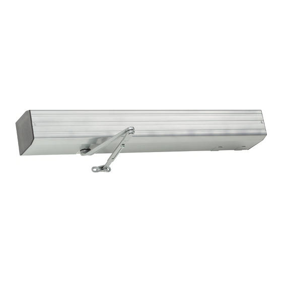
4630CS, 4640CS Electric Auto Equalizer Series
PULL SIDE MOUNT
The 4600CS Series electric Auto-Equalizer™ series combines all door
operator and door control functions in one package. This versatile,
easy-to-install system is low maintenance and offers the following
features:
Top jamb mounting on either side of an interior door allows 90°
of power opening. (Mounting for exterior door on the inside only)
Manual opening up to 170° (4630CS) or 100° (4640CS).
Quiet, reliable operator delivers consistent performance.
No expensive service contracts or periodic maintenance
required.
Fail safe operator acts as a standard door closer in event of
power outage.
Low energy operator does not require guard rails or safety mats.
Advanced, easy-to-install controller module allows independent
adjustment of:
a. Door Opening Speed
b. Delay / Trigger Time for Sequential Option
c. Door Opening Force
d. Electric Strike Delay Time
e. Hold Open Time
f. 90° Slow Down
g. Alternate Action Timeout
h. Safety Scanner Lockout Time
Customer Service
1-877-671-7011
4600CS Electronic Low
Energy Operator
4630CS
www.allegion.com/us
PUSH SIDE MOUNT

Table of Contents

Pg. 2 .......... General Information
Pg. 3 .......... Install Mounting Plate
Pg. 4 .......... 4630CS Template
Pg. 5 .......... 4640CS Template
Pg. 6 .......... Installing Closer Assembly
Pg.7-8......... 4600CS Series Arm Installation
Pg. 9 .......... Closer Regulation & Power Adjustment
Pg. 10 ........ Controller Installation
Pg. 11 ........ Electrical Connections
Pg.12-13..... Typical Wiring
Pg.14 ......... Auxiliary Electrical Device Wiring
Pg.15 ......... Controller Setting Adjustment
Pg. 16-17.... Controller Programming
Pg.18 ......... Basic Operation & Cover Installation
Pg.19 ......... Illustrated Parts List
Installation Instructions
4640CS

Advertisement

Table of Contents
loading
Need help?

Need help?

Do you have a question about the 4630CS and is the answer not in the manual?

Questions and answers

Summary of Contents for LCN 4630CS

  • Page 1 Pg. 4 ..4630CS Template of power opening. (Mounting for exterior door on the inside only) Pg. 5 ..4640CS Template • Manual opening up to 170° (4630CS) or 100° (4640CS). Pg. 6 ..Installing Closer Assembly • Quiet, reliable operator delivers consistent performance.
  • Page 2 ANSI A156.19 General Information requirements. To verify the force requirements, a force gauge is needed. If you have any questions, call LCN at 866 - 671 - 7011. The 4600CS series Auto-Equalizer™ is designed to meet the following codes & standards: •...
  • Page 3 & low voltage conduit lines to the operator. Fig. 3 HIGH VOLTAGE CONNECTION 1. Prepare door and frame per template on page 4 for 4630CS/ page 5 for 4640CS. Be sure all holes are located correctly LOW VOLTAGE before drilling and/or tapping. Mounting surface of frame CONNECTION must be vertically level.
  • Page 4 Page 4...
  • Page 5 PUSH SIDE/TOP JAMB MOUNT 4640CS SERIES PUSH SIDE/TOP JAMB MOUNTED NON-HANDED AUTO-EQUALIZER™ 100° OPENING MAX. 4640CS 90° POWER OPENING REGULAR/FLUSH CEILING MOUNTS LEFT HAND SHOWN, RIGHT HAND OPPOSITE PUSH SIDE/TOP JAMB MOUNT 100° OPENING MAX. 4640CS 90° POWER OPENING LEFT HAND SHOWN, RIGHT HAND OPPOSITE 1.
  • Page 6 Verify that closing force is not more than 15 lbs when measured SECTION 2 one inch from door edge to comply with ANSI A156.19. INSTALLING CLOSER ASSEMBLY TABLE 1 1. At this point of the installation, the mounting channel INTERIOR DOOR assembly should be attached securely to door frame.
  • Page 7 4630CS Series Arm Assembly NOTE: Right hand door shown, left hand will be opposite. Fig. 6 30° ROLLER END CAP LOCK WASHER 5/16" EXTENSION ARM SET SCREW SHAFT SPACER ASSY TRACK SHAFT PLUG SCREW (2) 1/4 - 20 x 1 1/2" M.S.
  • Page 8 4640CS Series Arm Assembly NOTE: Left hand door shown, Right hand will be opposite. Fig. 7 NOTE: Left hand door shown, Right hand will be opposite. " LOCK WASHER 5/16 EXTENSION ROD & SHOE FOREARM TUBE ARM SET SCREW MAIN Fig.
  • Page 9 FOR 4640CS SERIES ONLY: To adjust for additional closing DOOR CLOSER HYDRAULIC REGULATION & power at latch: POWER ADJUSTMENT a. Remove forearm set screw and open door, separating rod from forearm tube. 1. CLOSING SPEED ADJUSTMENT: (See Fig. 9) b. Remove shoe screws and flip shoe 180° as shown in Fig. The hydraulic regulation of the 4600CS series has been 10.
  • Page 10 SECTION 3 WIRING CONNECTIONS: 1. There will be 3 keyed wiring harness connectors shipped in the INSTALLATION & ADJUSTMENT hardware box. The first is a ribbon cable connector. It should OF CONTROLLER BOARD be fitted into receptacles on rear board assembly and the controller as shown in CONNECTION #1 of Fig.
  • Page 11 ELECTRICAL CONNECTIONS - Use copper wire only. HIGH VOLTAGE ELECTRICAL CONNECTIONS HAZARDOUS VOLTAGE CAN SHOCK AND CAUSE SEVERE INJURY. Disconnect power before making any electrical connections or performing POWER SWITCH any maintenance. ON INSIDE OF PLATE FIRE ALARM SHUNT TO CONNECT TO FIRE ALARM, CLIP LEADS ON SHUNT TO GROUND WIRE REMOVE AND CONNECT...
  • Page 12 SIMULTANEOUS PAIR WIRING CONNECTIONS ANY NORMALLY OPEN DRY CONTACT ACTUATOR SEQUENTIAL WIRING CONNECTIONS - SIMULTANEOUS VESTIBULE ANY NORMALLY OPEN DRY CONTACT ACTUATOR VESTIBULE ACTUATOR SEQUENTIAL SEQUENTIAL ACTUATOR ACTUATOR SEQUENTIAL WIRING CONNECTIONS - INDEPENDENT VESTIBULE ANY NORMALLY OPEN VESTIBULE DRY CONTACT ACTUATOR ACTUATOR VESTIBULE ACTUATOR...
  • Page 13 SEQUENTIAL PAIR WIRING CONNECTIONS - SIMULTANEOUS VESTIBULE SEQUENTIAL ACTUATOR VESTIBULE ACTUATOR SEQUENTIAL ACTUATOR SEQUENTIAL PAIR WIRING CONNECTIONS - INDEPENDENT VESTIBULE PAIRS VESTIBULE ACTUATOR SEQUENTIAL ACTUATOR VESTIBULE SEQUENTIAL ACTUATOR ACTUATOR Page 13...
  • Page 14 EARTH GROUND 120V NEUTRAL 120V HOT WIRING INFORMATION FOR ELECTRIC STRIKE / MAG-LOCK SYSTEM 24V DC 12V DC 24V DC 12V DC FOR ADDITIONAL WIRING INFORMATION CONTACT LCN CLOSERS ELECTRICAL APPLICATIONS DEPT. AT 800 - 671 - 7011 Page 14...
  • Page 15 CONTROLLER SETTING ADJUSTMENTS Consult diagram above. Each setting / indicators labeled #1 - #9, which correspond with numbers below. Adjustments for #2 & #3 are made with a small flat blade screwdriver. Turn clockwise to increase speed / force or counterclockwise to decrease speed / force. Controller functions are preset before shipment.
  • Page 16 CONTROLLER PROGRAMMING MODES DOWN MODE HOLD OPEN TIME POWER 90° SLOW DOWN TIME FIRE ALARM ONE SHOT INPUT NORMAL / SEQ EXTERIOR MODE H.O. / ALT. ACTION E.S. DELAY LOCKOUT TIMER E.S. 3 SEC. POWER SAFETY CLEAR SEQUENTIAL DELAY SAFETY ACTIVE ALTERNATE ACTION TIME LOCKOUT TIME OPERATING...
  • Page 17 LOCKOUT TIME indicator will be lit and display will show CONTROLLER PROGRAMMING programmed time. To change time, press UP or DOWN button respectively. Adjustment 0 to 66. Default 20. To exit programming Apply power to operator after all components are installed. mode, press mode button to return to RUN mode (display blank).
  • Page 18 or air pressure problems occur. TABLE 3 (below) lists the maximum door opening speeds specified by ANSI 156.19 for Low - Energy Door Operators. c. Controller goes into HOLD OPEN DELAY mode for preset 4630/4640 max. opening speed to 90° is 5 seconds. If weight of amount of time.
  • Page 19 4630CS/4640CS REPLACEMENT PARTS LIST INFORMATION When ordering replacement parts remember to specify Model (4630 or 4640) in front on the desired part #. Also specify Color / Finish when required. - 334CS - 20 CONDUIT SWITCH COVER END CAP -155G...
  • Page 20 © Allegion 2014 Printed in U.S.A. 29268 Rev. 01/14-e...
  • Page 21 Release Date White Paper R. Byun M. Sasso 043812 01-01-14 Notes Title 1. printed two sides 4630CS/4640CS Series Instruction Manual 2. printed black Creation Date Number Revision 3. tolerance ± .13 11-15-08 4. printed in country may vary 29268 5. drawings not to scale Created By 6.

This manual is also suitable for:

4640cs4600cs

Table of Contents